
1. Introduction
Proxmox VE is a platform to run virtual machines and containers. It is based on Debian Linux, and completely open source. For maximum flexibility, we implemented two virtualization technologies - Kernel-based Virtual Machine (KVM) and container-based virtualization (LXC).
One main design goal was to make administration as easy as possible. You can use Proxmox VE on a single node, or assemble a cluster of many nodes. All management tasks can be done using our web-based management interface, and even a novice user can setup and install Proxmox VE within minutes.

1.1. Central Management
While many people start with a single node, Proxmox VE can scale out to a large set of clustered nodes. The cluster stack is fully integrated and ships with the default installation.
- Unique Multi-Master Design
-
The integrated web-based management interface gives you a clean overview of all your KVM guests and Linux containers and even of your whole cluster. You can easily manage your VMs and containers, storage or cluster from the GUI. There is no need to install a separate, complex, and pricey management server.
- Proxmox Cluster File System (pmxcfs)
-
Proxmox VE uses the unique Proxmox Cluster file system (pmxcfs), a database-driven file system for storing configuration files. This enables you to store the configuration of thousands of virtual machines. By using corosync, these files are replicated in real time on all cluster nodes. The file system stores all data inside a persistent database on disk, nonetheless, a copy of the data resides in RAM which provides a maximum storage size of 30MB - more than enough for thousands of VMs.
Proxmox VE is the only virtualization platform using this unique cluster file system.
- Web-based Management Interface
-
Proxmox VE is simple to use. Management tasks can be done via the included web based management interface - there is no need to install a separate management tool or any additional management node with huge databases. The multi-master tool allows you to manage your whole cluster from any node of your cluster. The central web-based management - based on the JavaScript Framework (ExtJS) - empowers you to control all functionalities from the GUI and overview history and syslogs of each single node. This includes running backup or restore jobs, live-migration or HA triggered activities.
- Command Line
-
For advanced users who are used to the comfort of the Unix shell or Windows Powershell, Proxmox VE provides a command-line interface to manage all the components of your virtual environment. This command-line interface has intelligent tab completion and full documentation in the form of UNIX man pages.
- REST API
-
Proxmox VE uses a RESTful API. We choose JSON as primary data format, and the whole API is formally defined using JSON Schema. This enables fast and easy integration for third party management tools like custom hosting environments.
- Role-based Administration
-
You can define granular access for all objects (like VMs, storages, nodes, etc.) by using the role based user- and permission management. This allows you to define privileges and helps you to control access to objects. This concept is also known as access control lists: Each permission specifies a subject (a user or group) and a role (set of privileges) on a specific path.
- Authentication Realms
-
Proxmox VE supports multiple authentication sources like Microsoft Active Directory, LDAP, Linux PAM standard authentication or the built-in Proxmox VE authentication server.
1.2. Flexible Storage
The Proxmox VE storage model is very flexible. Virtual machine images can either be stored on one or several local storages or on shared storage like NFS and on SAN. There are no limits, you may configure as many storage definitions as you like. You can use all storage technologies available for Debian Linux.
One major benefit of storing VMs on shared storage is the ability to live-migrate running machines without any downtime, as all nodes in the cluster have direct access to VM disk images.
We currently support the following Network storage types:
-
LVM Group (network backing with iSCSI targets)
-
iSCSI target
-
NFS Share
-
CIFS Share
-
Ceph RBD
-
Directly use iSCSI LUNs
-
GlusterFS
Local storage types supported are:
-
LVM Group (local backing devices like block devices, FC devices, DRBD, etc.)
-
Directory (storage on existing filesystem)
-
ZFS
1.3. Integrated Backup and Restore
The integrated backup tool (vzdump) creates consistent snapshots of running Containers and KVM guests. It basically creates an archive of the VM or CT data which includes the VM/CT configuration files.
KVM live backup works for all storage types including VM images on NFS, CIFS, iSCSI LUN, Ceph RBD. The new backup format is optimized for storing VM backups fast and effective (sparse files, out of order data, minimized I/O).
1.4. High Availability Cluster
A multi-node Proxmox VE HA Cluster enables the definition of highly available virtual servers. The Proxmox VE HA Cluster is based on proven Linux HA technologies, providing stable and reliable HA services.
1.5. Flexible Networking
Proxmox VE uses a bridged networking model. All VMs can share one bridge as if virtual network cables from each guest were all plugged into the same switch. For connecting VMs to the outside world, bridges are attached to physical network cards and assigned a TCP/IP configuration.
For further flexibility, VLANs (IEEE 802.1q) and network bonding/aggregation are possible. In this way it is possible to build complex, flexible virtual networks for the Proxmox VE hosts, leveraging the full power of the Linux network stack.
1.6. Integrated Firewall
The integrated firewall allows you to filter network packets on any VM or Container interface. Common sets of firewall rules can be grouped into “security groups”.
1.7. Hyper-converged Infrastructure
Proxmox VE is a virtualization platform that tightly integrates compute, storage and networking resources, manages highly available clusters, backup/restore as well as disaster recovery. All components are software-defined and compatible with one another.
Therefore it is possible to administrate them like a single system via the centralized web management interface. These capabilities make Proxmox VE an ideal choice to deploy and manage an open source hyper-converged infrastructure.
1.7.1. Benefits of a Hyper-Converged Infrastructure (HCI) with Proxmox VE
A hyper-converged infrastructure (HCI) is especially useful for deployments in which a high infrastructure demand meets a low administration budget, for distributed setups such as remote and branch office environments or for virtual private and public clouds.
HCI provides the following advantages:
-
Scalability: seamless expansion of compute, network and storage devices (i.e. scale up servers and storage quickly and independently from each other).
-
Low cost: Proxmox VE is open source and integrates all components you need such as compute, storage, networking, backup, and management center. It can replace an expensive compute/storage infrastructure.
-
Data protection and efficiency: services such as backup and disaster recovery are integrated.
-
Simplicity: easy configuration and centralized administration.
-
Open Source: No vendor lock-in.
1.7.2. Hyper-Converged Infrastructure: Storage
Proxmox VE has tightly integrated support for deploying a hyper-converged storage infrastructure. You can, for example, deploy and manage the following two storage technologies by using the web interface only:
-
Ceph: a both self-healing and self-managing shared, reliable and highly scalable storage system. Checkout how to manage Ceph services on Proxmox VE nodes
-
ZFS: a combined file system and logical volume manager with extensive protection against data corruption, various RAID modes, fast and cheap snapshots - among other features. Find out how to leverage the power of ZFS on Proxmox VE nodes.
Besides above, Proxmox VE has support to integrate a wide range of additional storage technologies. You can find out about them in the Storage Manager chapter.
1.8. Why Open Source
Proxmox VE uses a Linux kernel and is based on the Debian GNU/Linux Distribution. The source code of Proxmox VE is released under the GNU Affero General Public License, version 3. This means that you are free to inspect the source code at any time or contribute to the project yourself.
At Proxmox we are committed to use open source software whenever possible. Using open source software guarantees full access to all functionalities - as well as high security and reliability. We think that everybody should have the right to access the source code of a software to run it, build on it, or submit changes back to the project. Everybody is encouraged to contribute while Proxmox ensures the product always meets professional quality criteria.
Open source software also helps to keep your costs low and makes your core infrastructure independent from a single vendor.
1.9. Your benefits with Proxmox VE
-
Open source software
-
No vendor lock-in
-
Linux kernel
-
Fast installation and easy-to-use
-
Web-based management interface
-
REST API
-
Huge active community
-
Low administration costs and simple deployment
1.10. Getting Help
1.10.1. Proxmox VE Wiki
The primary source of information is the Proxmox VE Wiki. It combines the reference documentation with user contributed content.
1.10.2. Community Support Forum
Proxmox VE itself is fully open source, so we always encourage our users to discuss and share their knowledge using the Proxmox VE Community Forum. The forum is moderated by the Proxmox support team, and has a large user base from all around the world. Needless to say, such a large forum is a great place to get information.
1.10.3. Mailing Lists
This is a fast way to communicate with the Proxmox VE community via email.
-
Mailing list for users: Proxmox VE User List
Proxmox VE is fully open source and contributions are welcome! The primary communication channel for developers is the:
-
Mailing list for developers: Proxmox VE development discussion
1.10.4. Commercial Support
Proxmox Server Solutions GmbH also offers enterprise support available as Proxmox VE Subscription Service Plans. All users with a subscription get access to the Proxmox VE Enterprise Repository, and—with a Basic, Standard or Premium subscription—also to the Proxmox Customer Portal. The customer portal provides help and support with guaranteed response times from the Proxmox VE developers.
For volume discounts, or more information in general, please contact sales@proxmox.com.
1.10.5. Bug Tracker
Proxmox runs a public bug tracker at https://bugzilla.proxmox.com. If an issue appears, file your report there. An issue can be a bug as well as a request for a new feature or enhancement. The bug tracker helps to keep track of the issue and will send a notification once it has been solved.
1.11. Project History
The project started in 2007, followed by a first stable version in 2008. At the time we used OpenVZ for containers, and KVM for virtual machines. The clustering features were limited, and the user interface was simple (server generated web page).
But we quickly developed new features using the Corosync cluster stack, and the introduction of the new Proxmox cluster file system (pmxcfs) was a big step forward, because it completely hides the cluster complexity from the user. Managing a cluster of 16 nodes is as simple as managing a single node.
We also introduced a new REST API, with a complete declarative specification written in JSON-Schema. This enabled other people to integrate Proxmox VE into their infrastructure, and made it easy to provide additional services.
Also, the new REST API made it possible to replace the original user interface with a modern HTML5 application using JavaScript. We also replaced the old Java based VNC console code with noVNC. So you only need a web browser to manage your VMs.
The support for various storage types is another big task. Notably, Proxmox VE was the first distribution to ship ZFS on Linux by default in 2014. Another milestone was the ability to run and manage Ceph storage on the hypervisor nodes. Such setups are extremely cost effective.
When we started we were among the first companies providing commercial support for KVM. The KVM project itself continuously evolved, and is now a widely used hypervisor. New features arrive with each release. We developed the KVM live backup feature, which makes it possible to create snapshot backups on any storage type.
The most notable change with version 4.0 was the move from OpenVZ to LXC. Containers are now deeply integrated, and they can use the same storage and network features as virtual machines.
1.12. Improving the Proxmox VE Documentation
Contributions and improvements to the Proxmox VE documentation are always welcome. There are several ways to contribute.
If you find errors or other room for improvement in this documentation, please file a bug at the Proxmox bug tracker to propose a correction.
If you want to propose new content, choose one of the following options:
-
The wiki: For specific setups, how-to guides, or tutorials the wiki is the right option to contribute.
-
The reference documentation: For general content that will be helpful to all users please propose your contribution for the reference documentation. This includes all information about how to install, configure, use, and troubleshoot Proxmox VE features. The reference documentation is written in the asciidoc format. To edit the documentation you need to clone the git repository at git://git.proxmox.com/git/pve-docs.git; then follow the README.adoc document.

|
If you are interested in working on the Proxmox VE codebase, the Developer Documentation wiki article will show you where to start. |
1.13. Translating Proxmox VE
The Proxmox VE user interface is in English by default. However, thanks to the contributions of the community, translations to other languages are also available. We welcome any support in adding new languages, translating the latest features, and improving incomplete or inconsistent translations.
We use gettext for the management of the translation files. Tools like Poedit offer a nice user interface to edit the translation files, but you can use whatever editor you’re comfortable with. No programming knowledge is required for translating.
1.13.1. Translating with git
The language files are available as a git repository. If you are familiar with git, please contribute according to our Developer Documentation.
You can create a new translation by doing the following (replace <LANG> with the language ID):
# git clone git://git.proxmox.com/git/proxmox-i18n.git
# cd proxmox-i18n
# make init-<LANG>.po
Or you can edit an existing translation, using the editor of your choice:
# poedit <LANG>.po
1.13.2. Translating without git
Even if you are not familiar with git, you can help translate Proxmox VE. To start, you can download the language files here. Find the language you want to improve, then right click on the "raw" link of this language file and select Save Link As…. Make your changes to the file, and then send your final translation directly to office(at)proxmox.com, together with a signed contributor license agreement.
1.13.3. Testing the Translation
In order for the translation to be used in Proxmox VE, you must first translate the .po file into a .js file. You can do this by invoking the following script, which is located in the same repository:
# ./po2js.pl -t pve xx.po >pve-lang-xx.js
The resulting file pve-lang-xx.js can then be copied to the directory /usr/share/pve-i18n, on your proxmox server, in order to test it out.
Alternatively, you can build a deb package by running the following command from the root of the repository:
# make deb

|
For either of these methods to work, you need to have the following perl packages installed on your system. For Debian/Ubuntu: |
# apt-get install perl liblocale-po-perl libjson-perl
1.13.4. Sending the Translation
You can send the finished translation (.po file) to the Proxmox team at the address office(at)proxmox.com, along with a signed contributor license agreement. Alternatively, if you have some developer experience, you can send it as a patch to the Proxmox VE development mailing list. See Developer Documentation.
2. Installing Proxmox VE
Proxmox VE is based on Debian. This is why the install disk images (ISO files) provided by Proxmox include a complete Debian system as well as all necessary Proxmox VE packages.

|
See the support table in the FAQ for the relationship between Proxmox VE releases and Debian releases. |
The installer will guide you through the setup, allowing you to partition the local disk(s), apply basic system configurations (for example, timezone, language, network) and install all required packages. This process should not take more than a few minutes. Installing with the provided ISO is the recommended method for new and existing users.
Alternatively, Proxmox VE can be installed on top of an existing Debian system. This option is only recommended for advanced users because detailed knowledge about Proxmox VE is required.
2.1. System Requirements
We recommend using high quality server hardware, when running Proxmox VE in production. To further decrease the impact of a failed host, you can run Proxmox VE in a cluster with highly available (HA) virtual machines and containers.
Proxmox VE can use local storage (DAS), SAN, NAS, and distributed storage like Ceph RBD. For details see chapter storage.
2.1.1. Minimum Requirements, for Evaluation
These minimum requirements are for evaluation purposes only and should not be used in production.
-
CPU: 64bit (Intel EMT64 or AMD64)
-
Intel VT/AMD-V capable CPU/motherboard for KVM full virtualization support
-
RAM: 1 GB RAM, plus additional RAM needed for guests
-
Hard drive
-
One network card (NIC)
2.1.2. Recommended System Requirements
-
Intel EMT64 or AMD64 with Intel VT/AMD-V CPU flag.
-
Memory: Minimum 2 GB for the OS and Proxmox VE services, plus designated memory for guests. For Ceph and ZFS, additional memory is required; approximately 1GB of memory for every TB of used storage.
-
Fast and redundant storage, best results are achieved with SSDs.
-
OS storage: Use a hardware RAID with battery protected write cache (“BBU”) or non-RAID with ZFS (optional SSD for ZIL).
-
VM storage:
-
For local storage, use either a hardware RAID with battery backed write cache (BBU) or non-RAID for ZFS and Ceph. Neither ZFS nor Ceph are compatible with a hardware RAID controller.
-
Shared and distributed storage is possible.
-
SSDs with Power-Loss-Protection (PLP) are recommended for good performance. Using consumer SSDs is discouraged.
-
-
Redundant (Multi-)Gbit NICs, with additional NICs depending on the preferred storage technology and cluster setup.
-
For PCI(e) passthrough the CPU needs to support the VT-d/AMD-d flag.
2.1.3. Simple Performance Overview
To get an overview of the CPU and hard disk performance on an installed Proxmox VE system, run the included pveperf tool.
|
|
This is just a very quick and general benchmark. More detailed tests are recommended, especially regarding the I/O performance of your system. |
2.1.4. Supported Web Browsers for Accessing the Web Interface
To access the web-based user interface, we recommend using one of the following browsers:
-
Firefox, a release from the current year, or the latest Extended Support Release
-
Chrome, a release from the current year
-
Microsoft’s currently supported version of Edge
-
Safari, a release from the current year
When accessed from a mobile device, Proxmox VE will show a lightweight, touch-based interface.
2.2. Prepare Installation Media
Download the installer ISO image from: https://www.proxmox.com/en/downloads/proxmox-virtual-environment/iso
The Proxmox VE installation media is a hybrid ISO image. It works in two ways:
-
An ISO image file ready to burn to a CD or DVD.
-
A raw sector (IMG) image file ready to copy to a USB flash drive (USB stick).
Using a USB flash drive to install Proxmox VE is the recommended way because it is the faster option.
2.2.1. Prepare a USB Flash Drive as Installation Medium
The flash drive needs to have at least 1 GB of storage available.
|
|
Do not use UNetbootin. It does not work with the Proxmox VE installation image. |
|
|
Make sure that the USB flash drive is not mounted and does not contain any important data. |
2.2.2. Instructions for GNU/Linux
On Unix-like operating system use the dd command to copy the ISO image to the USB flash drive. First find the correct device name of the USB flash drive (see below). Then run the dd command.
# dd bs=1M conv=fdatasync if=./proxmox-ve_*.iso of=/dev/XYZ
|
|
Be sure to replace /dev/XYZ with the correct device name and adapt the input filename (if) path. |

|
Be very careful, and do not overwrite the wrong disk! |
Find the Correct USB Device Name
There are two ways to find out the name of the USB flash drive. The first one is to compare the last lines of the dmesg command output before and after plugging in the flash drive. The second way is to compare the output of the lsblk command. Open a terminal and run:
# lsblk
Then plug in your USB flash drive and run the command again:
# lsblk
A new device will appear. This is the one you want to use. To be on the extra safe side check if the reported size matches your USB flash drive.
2.2.3. Instructions for macOS
Open the terminal (query Terminal in Spotlight).
Convert the .iso file to .dmg format using the convert option of hdiutil, for example:
# hdiutil convert proxmox-ve_*.iso -format UDRW -o proxmox-ve_*.dmg
|
|
macOS tends to automatically add .dmg to the output file name. |
To get the current list of devices run the command:
# diskutil list
Now insert the USB flash drive and run this command again to determine which device node has been assigned to it. (e.g., /dev/diskX).
# diskutil list
# diskutil unmountDisk /dev/diskX
|
|
replace X with the disk number from the last command. |
# sudo dd if=proxmox-ve_*.dmg bs=1M of=/dev/rdiskX
|
|
rdiskX, instead of diskX, in the last command is intended. It will increase the write speed. |
2.2.4. Instructions for Windows
Using Etcher
Etcher works out of the box. Download Etcher from https://etcher.io. It will guide you through the process of selecting the ISO and your USB flash drive.
Using Rufus
Rufus is a more lightweight alternative, but you need to use the DD mode to make it work. Download Rufus from https://rufus.ie/. Either install it or use the portable version. Select the destination drive and the Proxmox VE ISO file.
|
|
Once you Start you have to click No on the dialog asking to download a different version of GRUB. In the next dialog select the DD mode. |
2.3. Using the Proxmox VE Installer
The installer ISO image includes the following:
-
Complete operating system (Debian Linux, 64-bit)
-
The Proxmox VE installer, which partitions the local disk(s) with ext4, XFS, BTRFS (technology preview), or ZFS and installs the operating system
-
Proxmox VE Linux kernel with KVM and LXC support
-
Complete toolset for administering virtual machines, containers, the host system, clusters and all necessary resources
-
Web-based management interface
|
|
All existing data on the selected drives will be removed during the installation process. The installer does not add boot menu entries for other operating systems. |
Please insert the prepared installation media (for example, USB flash drive or CD-ROM) and boot from it.
|
|
Make sure that booting from the installation medium (for example, USB) is enabled in your server’s firmware settings. Secure boot needs to be disabled when booting an installer prior to Proxmox VE version 8.1. |
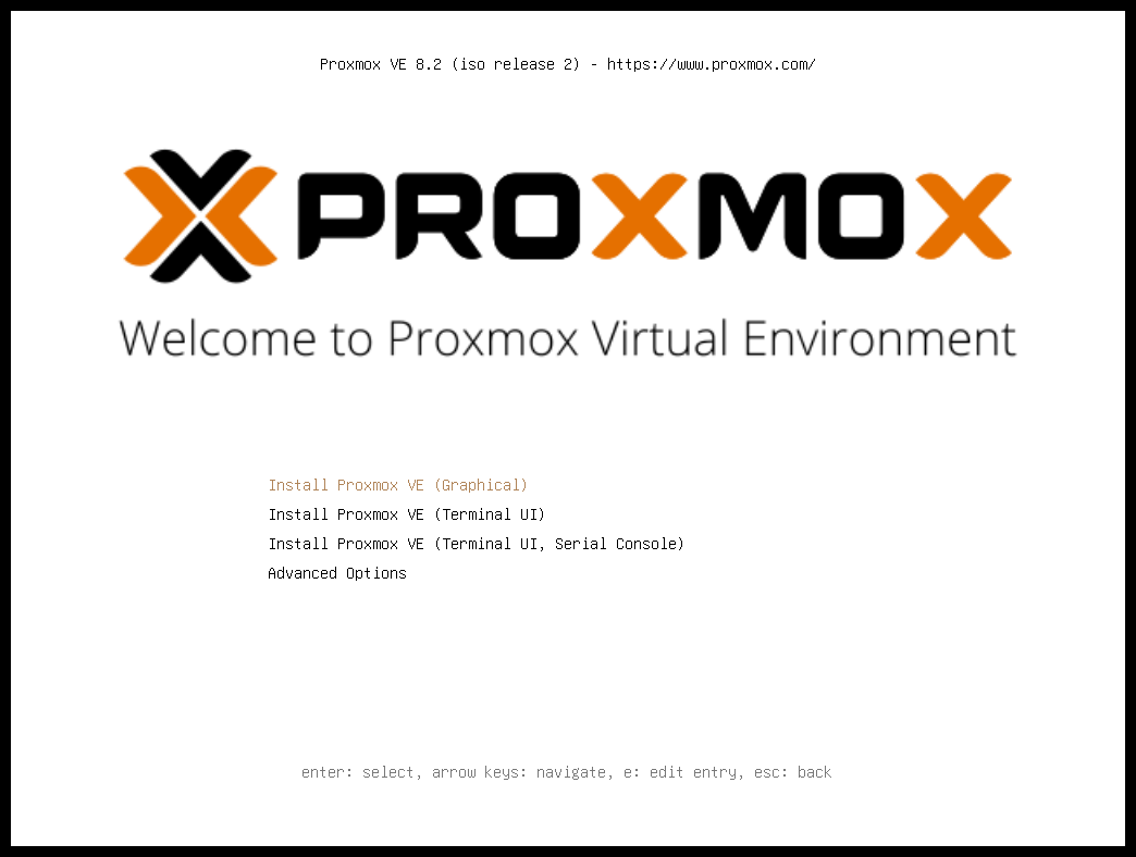
After choosing the correct entry (for example, Boot from USB) the Proxmox VE menu will be displayed, and one of the following options can be selected:
- Install Proxmox VE (Graphical)
-
Starts the normal installation.
|
|
It’s possible to use the installation wizard with a keyboard only. Buttons can be clicked by pressing the ALT key combined with the underlined character from the respective button. For example, ALT + N to press a Next button. |
- Install Proxmox VE (Terminal UI)
-
Starts the terminal-mode installation wizard. It provides the same overall installation experience as the graphical installer, but has generally better compatibility with very old and very new hardware.
- Install Proxmox VE (Terminal UI, Serial Console)
-
Starts the terminal-mode installation wizard, additionally setting up the Linux kernel to use the (first) serial port of the machine for in- and output. This can be used if the machine is completely headless and only has a serial console available.
Both modes use the same code base for the actual installation process to benefit from more than a decade of bug fixes and ensure feature parity.
|
|
The Terminal UI option can be used in case the graphical installer does not work correctly, due to e.g. driver issues. See also adding the nomodeset kernel parameter. |
- Advanced Options: Install Proxmox VE (Graphical, Debug Mode)
-
Starts the installation in debug mode. A console will be opened at several installation steps. This helps to debug the situation if something goes wrong. To exit a debug console, press CTRL-D. This option can be used to boot a live system with all basic tools available. You can use it, for example, to repair a degraded ZFS rpool or fix the bootloader for an existing Proxmox VE setup.
- Advanced Options: Install Proxmox VE (Terminal UI, Debug Mode)
-
Same as the graphical debug mode, but preparing the system to run the terminal-based installer instead.
- Advanced Options: Install Proxmox VE (Serial Console Debug Mode)
-
Same the terminal-based debug mode, but additionally sets up the Linux kernel to use the (first) serial port of the machine for in- and output.
- Advanced Options: Rescue Boot
-
With this option you can boot an existing installation. It searches all attached hard disks. If it finds an existing installation, it boots directly into that disk using the Linux kernel from the ISO. This can be useful if there are problems with the bootloader (GRUB/systemd-boot) or the BIOS/UEFI is unable to read the boot block from the disk.
- Advanced Options: Test Memory (memtest86+)
-
Runs memtest86+. This is useful to check if the memory is functional and free of errors. Secure Boot must be turned off in the UEFI firmware setup utility to run this option.
You normally select Install Proxmox VE (Graphical) to start the installation.
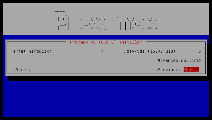
The first step is to read our EULA (End User License Agreement). Following this, you can select the target hard disk(s) for the installation.
|
|
By default, the whole server is used and all existing data is removed. Make sure there is no important data on the server before proceeding with the installation. |
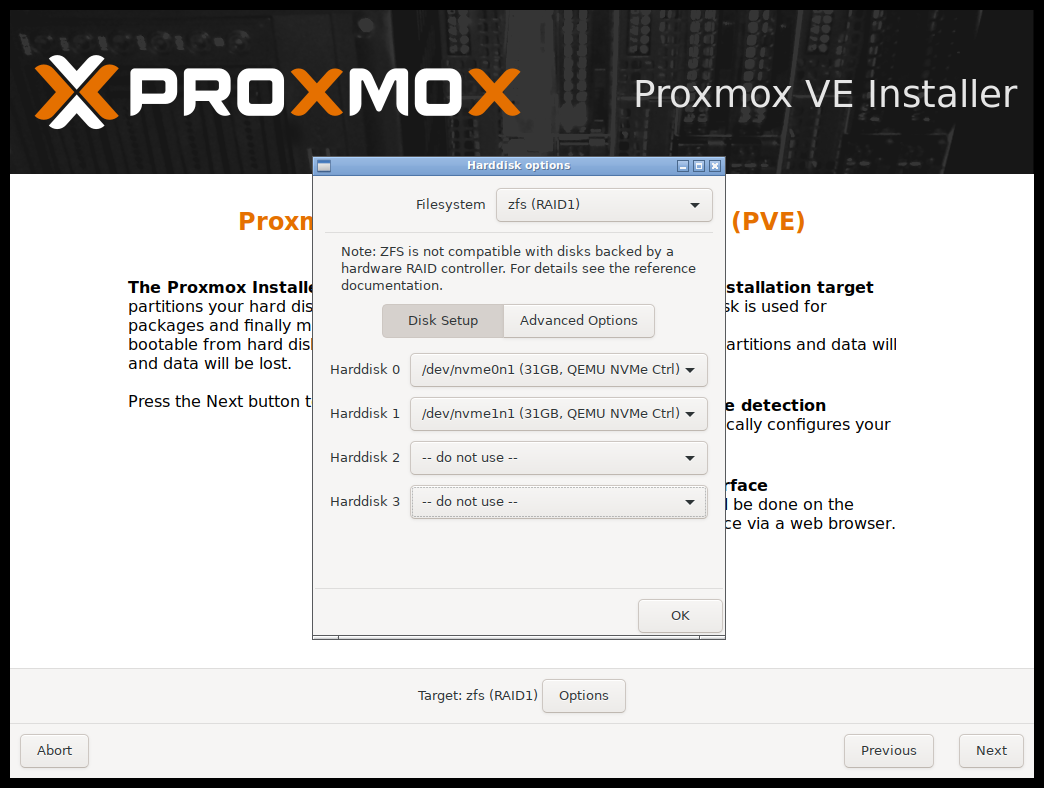
The Options button lets you select the target file system, which defaults to ext4. The installer uses LVM if you select ext4 or xfs as a file system, and offers additional options to restrict LVM space (see below).
Proxmox VE can also be installed on ZFS. As ZFS offers several software RAID levels, this is an option for systems that don’t have a hardware RAID controller. The target disks must be selected in the Options dialog. More ZFS specific settings can be changed under Advanced Options.

|
ZFS on top of any hardware RAID is not supported and can result in data loss. |

The next page asks for basic configuration options like your location, time zone, and keyboard layout. The location is used to select a nearby download server, in order to increase the speed of updates. The installer is usually able to auto-detect these settings, so you only need to change them in rare situations when auto-detection fails, or when you want to use a keyboard layout not commonly used in your country.
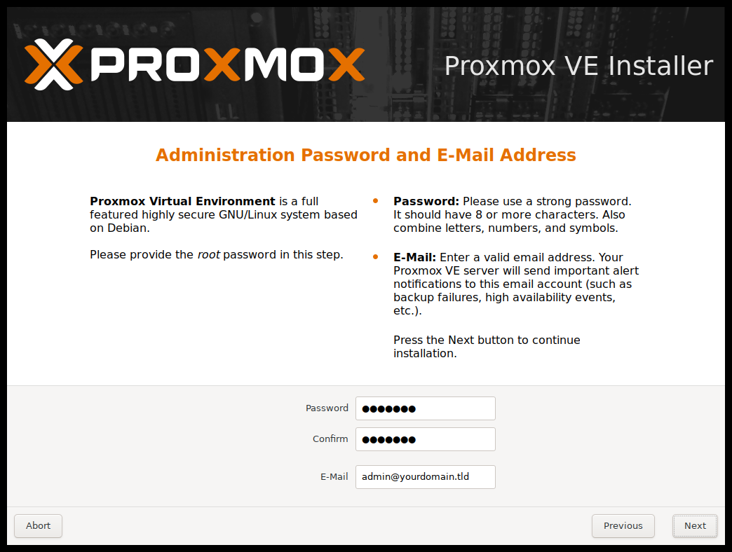
Next the password of the superuser (root) and an email address needs to be specified. The password must consist of at least 5 characters. It’s highly recommended to use a stronger password. Some guidelines are:
-
Use a minimum password length of at least 12 characters.
-
Include lowercase and uppercase alphabetic characters, numbers, and symbols.
-
Avoid character repetition, keyboard patterns, common dictionary words, letter or number sequences, usernames, relative or pet names, romantic links (current or past), and biographical information (for example ID numbers, ancestors' names or dates).
The email address is used to send notifications to the system administrator. For example:
-
Information about available package updates.
-
Error messages from periodic cron jobs.
All those notification mails will be sent to the specified email address.
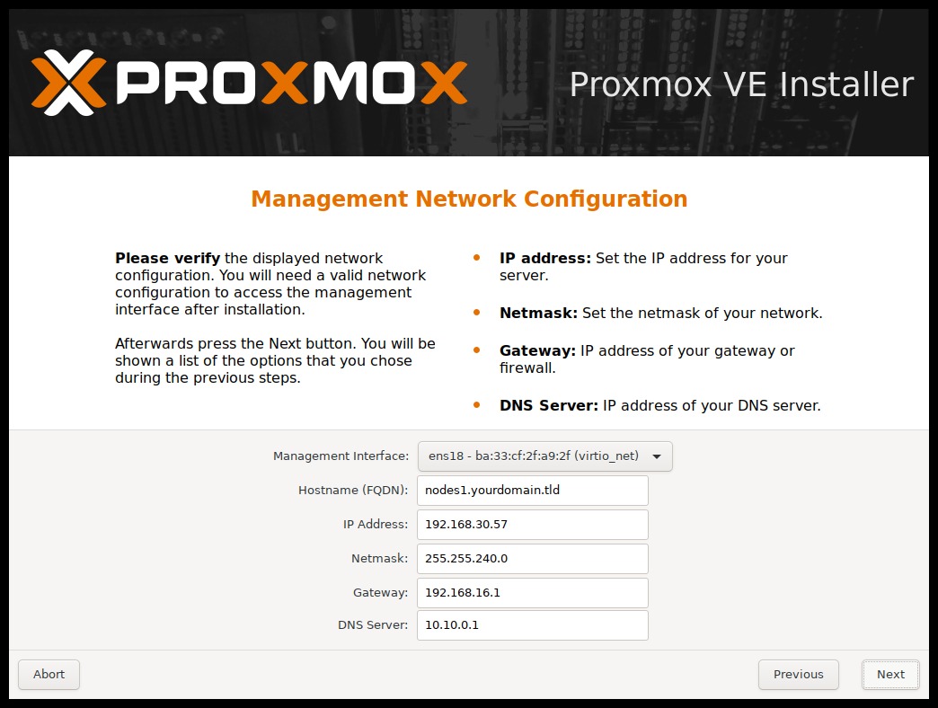
The last step is the network configuration. Network interfaces that are UP show a filled circle in front of their name in the drop down menu. Please note that during installation you can either specify an IPv4 or IPv6 address, but not both. To configure a dual stack node, add additional IP addresses after the installation.
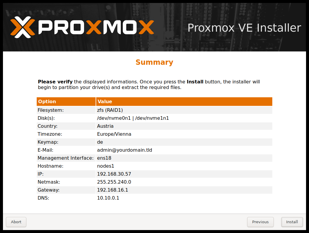
The next step shows a summary of the previously selected options. Please re-check every setting and use the Previous button if a setting needs to be changed.
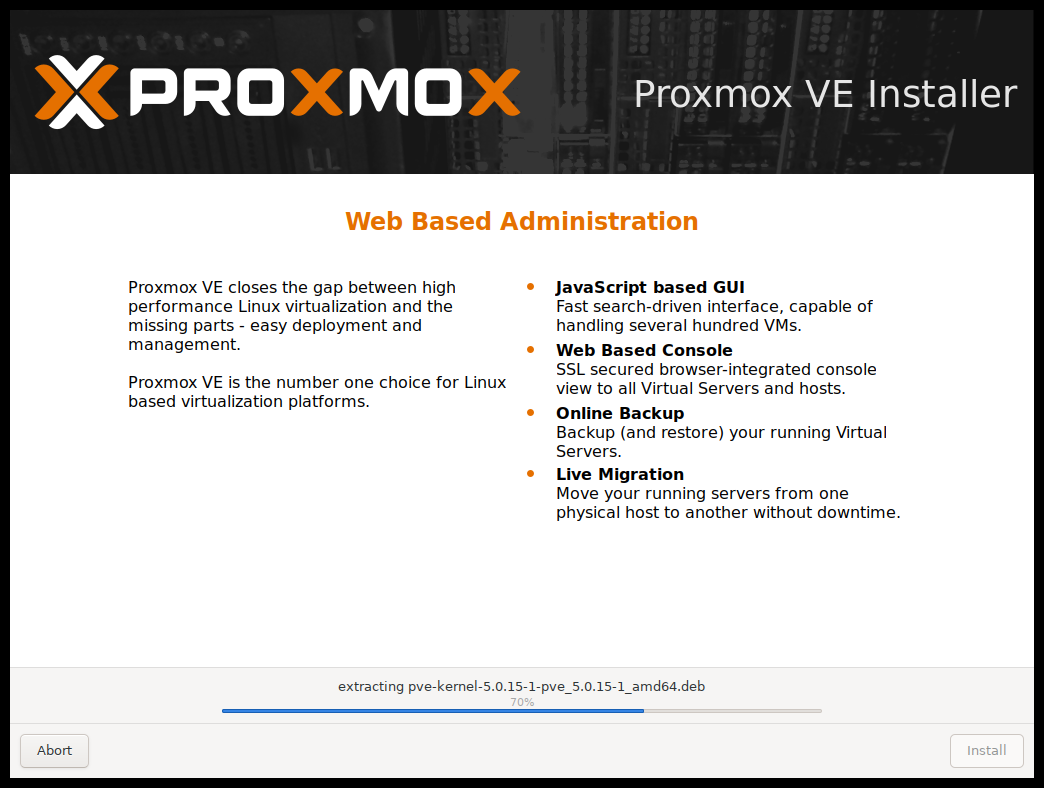
After clicking Install, the installer will begin to format the disks and copy packages to the target disk(s). Please wait until this step has finished; then remove the installation medium and restart your system.
Copying the packages usually takes several minutes, mostly depending on the speed of the installation medium and the target disk performance.
When copying and setting up the packages has finished, you can reboot the server. This will be done automatically after a few seconds by default.
If the installation failed, check out specific errors on the second TTY (CTRL + ALT + F2) and ensure that the systems meets the minimum requirements.
If the installation is still not working, look at the how to get help chapter.
2.3.1. Accessing the Management Interface Post-Installation
After a succesful installation and reboot of the system you can use the Proxmox VE web interface for further configuration.
-
Point your browser to the IP address given during the installation and port 8006, for example: https://youripaddress:8006
-
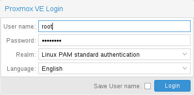
Log in using the root (realm PAM) username and the password chosen during installation.
-
Upload your subscription key to gain access to the Enterprise repository. Otherwise, you will need to set up one of the public, less tested package repositories to get updates for security fixes, bug fixes, and new features.
-
Check the IP configuration and hostname.
-
Check the timezone.
-
Check your Firewall settings.
2.3.2. Advanced LVM Configuration Options
The installer creates a Volume Group (VG) called pve, and additional Logical Volumes (LVs) called root, data, and swap, if ext4 or xfs is used. To control the size of these volumes use:
- hdsize
-
Defines the total hard disk size to be used. This way you can reserve free space on the hard disk for further partitioning (for example for an additional PV and VG on the same hard disk that can be used for LVM storage).
- swapsize
-
Defines the size of the swap volume. The default is the size of the installed memory, minimum 4 GB and maximum 8 GB. The resulting value cannot be greater than hdsize/8.
If set to 0, no swap volume will be created. - maxroot
-
Defines the maximum size of the root volume, which stores the operation system. The maximum limit of the root volume size is hdsize/4.
- maxvz
-
Defines the maximum size of the data volume. The actual size of the data volume is:
datasize = hdsize - rootsize - swapsize - minfree
Where datasize cannot be bigger than maxvz.
In case of LVM thin, the data pool will only be created if datasize is bigger than 4GB.
If set to 0, no data volume will be created and the storage configuration will be adapted accordingly. - minfree
-
Defines the amount of free space that should be left in the LVM volume group pve. With more than 128GB storage available, the default is 16GB, otherwise hdsize/8 will be used.
LVM requires free space in the VG for snapshot creation (not required for lvmthin snapshots).
2.3.3. Advanced ZFS Configuration Options
The installer creates the ZFS pool rpool, if ZFS is used. No swap space is created but you can reserve some unpartitioned space on the install disks for swap. You can also create a swap zvol after the installation, although this can lead to problems (see ZFS swap notes).
- ashift
-
Defines the ashift value for the created pool. The ashift needs to be set at least to the sector-size of the underlying disks (2 to the power of ashift is the sector-size), or any disk which might be put in the pool (for example the replacement of a defective disk).
- compress
-
Defines whether compression is enabled for rpool.
- checksum
-
Defines which checksumming algorithm should be used for rpool.
- copies
-
Defines the copies parameter for rpool. Check the zfs(8) manpage for the semantics, and why this does not replace redundancy on disk-level.
- ARC max size
-
Defines the maximum size the ARC can grow to and thus limits the amount of memory ZFS will use. See also the section on how to limit ZFS memory usage for more details.
- hdsize
-
Defines the total hard disk size to be used. This is useful to save free space on the hard disk(s) for further partitioning (for example to create a swap-partition). hdsize is only honored for bootable disks, that is only the first disk or mirror for RAID0, RAID1 or RAID10, and all disks in RAID-Z[123].
2.3.4. ZFS Performance Tips
ZFS works best with a lot of memory. If you intend to use ZFS make sure to have enough RAM available for it. A good calculation is 4GB plus 1GB RAM for each TB RAW disk space.
ZFS can use a dedicated drive as write cache, called the ZFS Intent Log (ZIL). Use a fast drive (SSD) for it. It can be added after installation with the following command:
# zpool add <pool-name> log </dev/path_to_fast_ssd>
2.3.5. Adding the nomodeset Kernel Parameter
Problems may arise on very old or very new hardware due to graphics drivers. If the installation hangs during boot, you can try adding the nomodeset parameter. This prevents the Linux kernel from loading any graphics drivers and forces it to continue using the BIOS/UEFI-provided framebuffer.
On the Proxmox VE bootloader menu, navigate to Install Proxmox VE (Terminal UI) and press e to edit the entry. Using the arrow keys, navigate to the line starting with linux, move the cursor to the end of that line and add the parameter nomodeset, separated by a space from the pre-existing last parameter.
Then press Ctrl-X or F10 to boot the configuration.
2.4. Unattended Installation
It is possible to install Proxmox VE automatically in an unattended manner. This enables you to fully automate the setup process on bare-metal. Once the installation is complete and the host has booted up, automation tools like Ansible can be used to further configure the installation.
The necessary options for the installer must be provided in an answer file. This file allows the use of filter rules to determine which disks and network cards should be used.
To use the automated installation, it is first necessary to prepare an installation ISO. Visit our wiki for more details and information on the unattended installation.
2.5. Install Proxmox VE on Debian
Proxmox VE ships as a set of Debian packages and can be installed on top of a standard Debian installation. After configuring the repositories you need to run the following commands:
# apt-get update
# apt-get install proxmox-ve
Installing on top of an existing Debian installation looks easy, but it presumes that the base system has been installed correctly and that you know how you want to configure and use the local storage. You also need to configure the network manually.
In general, this is not trivial, especially when LVM or ZFS is used.
A detailed step by step how-to can be found on the wiki.
3. Host System Administration
The following sections will focus on common virtualization tasks and explain the Proxmox VE specifics regarding the administration and management of the host machine.
Proxmox VE is based on Debian GNU/Linux with additional repositories to provide the Proxmox VE related packages. This means that the full range of Debian packages is available including security updates and bug fixes. Proxmox VE provides its own Linux kernel based on the Ubuntu kernel. It has all the necessary virtualization and container features enabled and includes ZFS and several extra hardware drivers.
For other topics not included in the following sections, please refer to the Debian documentation. The Debian Administrator's Handbook is available online, and provides a comprehensive introduction to the Debian operating system (see [Hertzog13]).
3.1. Package Repositories
Proxmox VE uses APT as its package management tool like any other Debian-based system.
Proxmox VE automatically checks for package updates on a daily basis. The root@pam user is notified via email about available updates. From the GUI, the Changelog button can be used to see more details about an selected update.
3.1.1. Repositories in Proxmox VE
Repositories are a collection of software packages, they can be used to install new software, but are also important to get new updates.
|
|
You need valid Debian and Proxmox repositories to get the latest security updates, bug fixes and new features. |
APT Repositories are defined in the file /etc/apt/sources.list and in .list files placed in /etc/apt/sources.list.d/.
Repository Management
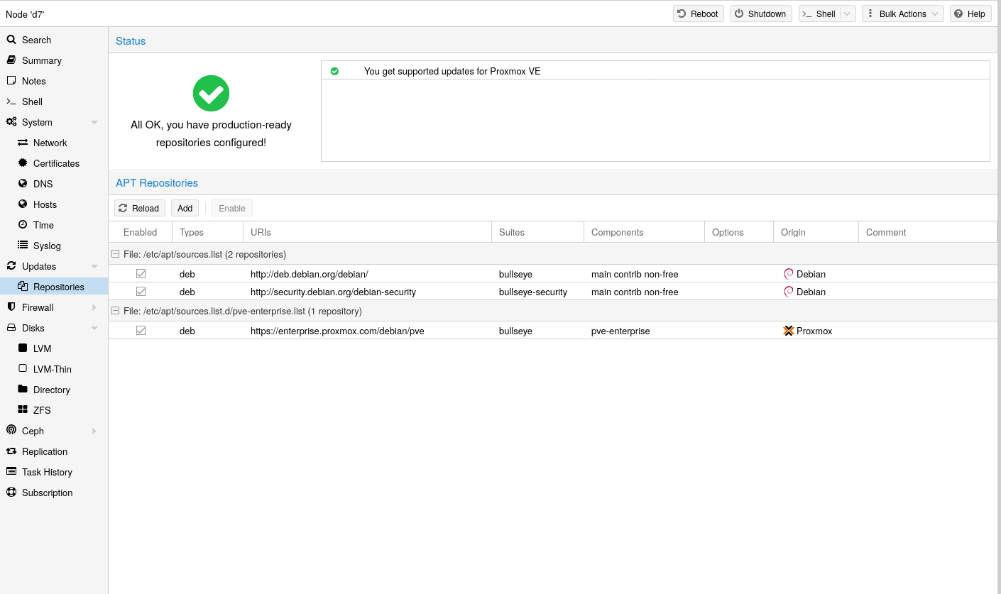
Since Proxmox VE 7, you can check the repository state in the web interface. The node summary panel shows a high level status overview, while the separate Repository panel shows in-depth status and list of all configured repositories.
Basic repository management, for example, activating or deactivating a repository, is also supported.
Sources.list
In a sources.list file, each line defines a package repository. The preferred source must come first. Empty lines are ignored. A # character anywhere on a line marks the remainder of that line as a comment. The available packages from a repository are acquired by running apt-get update. Updates can be installed directly using apt-get, or via the GUI (Node → Updates).
deb http://deb.debian.org/debian bookworm main contrib
deb http://deb.debian.org/debian bookworm-updates main contrib

# security updates
deb http://security.debian.org/debian-security bookworm-security main contrib
Proxmox VE provides three different package repositories.
3.1.2. Proxmox VE Enterprise Repository
This is the recommended repository and available for all Proxmox VE subscription users. It contains the most stable packages and is suitable for production use. The pve-enterprise repository is enabled by default:
deb https://enterprise.proxmox.com/debian/pve bookworm pve-enterprise
Please note that you need a valid subscription key to access the pve-enterprise repository. We offer different support levels, which you can find further details about at https://proxmox.com/en/proxmox-virtual-environment/pricing.
|
|
You can disable this repository by commenting out the above line using a # (at the start of the line). This prevents error messages if your host does not have a subscription key. Please configure the pve-no-subscription repository in that case. |
3.1.3. Proxmox VE No-Subscription Repository
As the name suggests, you do not need a subscription key to access this repository. It can be used for testing and non-production use. It’s not recommended to use this on production servers, as these packages are not always as heavily tested and validated.
We recommend to configure this repository in /etc/apt/sources.list.
deb http://ftp.debian.org/debian bookworm main contrib
deb http://ftp.debian.org/debian bookworm-updates main contrib

# Proxmox VE pve-no-subscription repository provided by proxmox.com,
# NOT recommended for production use
deb http://download.proxmox.com/debian/pve bookworm pve-no-subscription

# security updates
deb http://security.debian.org/debian-security bookworm-security main contrib
3.1.4. Proxmox VE Test Repository
This repository contains the latest packages and is primarily used by developers to test new features. To configure it, add the following line to /etc/apt/sources.list:
deb http://download.proxmox.com/debian/pve bookworm pvetest
|
|
The pvetest repository should (as the name implies) only be used for testing new features or bug fixes. |
3.1.5. Ceph Reef Enterprise Repository
This repository holds the enterprise Proxmox VE Ceph 18.2 Reef packages. They are suitable for production. Use this repository if you run the Ceph client or a full Ceph cluster on Proxmox VE.
deb https://enterprise.proxmox.com/debian/ceph-reef bookworm enterprise
3.1.6. Ceph Reef No-Subscription Repository
This Ceph repository contains the Ceph 18.2 Reef packages before they are moved to the enterprise repository and after they where on the test repository.
|
|
It’s recommended to use the enterprise repository for production machines. |
deb http://download.proxmox.com/debian/ceph-reef bookworm no-subscription
3.1.7. Ceph Reef Test Repository
This Ceph repository contains the Ceph 18.2 Reef packages before they are moved to the main repository. It is used to test new Ceph releases on Proxmox VE.
deb http://download.proxmox.com/debian/ceph-reef bookworm test
3.1.8. Ceph Quincy Enterprise Repository
This repository holds the enterprise Proxmox VE Ceph Quincy packages. They are suitable for production. Use this repository if you run the Ceph client or a full Ceph cluster on Proxmox VE.
deb https://enterprise.proxmox.com/debian/ceph-quincy bookworm enterprise
3.1.9. Ceph Quincy No-Subscription Repository
This Ceph repository contains the Ceph Quincy packages before they are moved to the enterprise repository and after they where on the test repository.
|
|
It’s recommended to use the enterprise repository for production machines. |
deb http://download.proxmox.com/debian/ceph-quincy bookworm no-subscription
3.1.10. Ceph Quincy Test Repository
This Ceph repository contains the Ceph Quincy packages before they are moved to the main repository. It is used to test new Ceph releases on Proxmox VE.
deb http://download.proxmox.com/debian/ceph-quincy bookworm test
3.1.11. Older Ceph Repositories
Proxmox VE 8 doesn’t support Ceph Pacific, Ceph Octopus, or even older releases for hyper-converged setups. For those releases, you need to first upgrade Ceph to a newer release before upgrading to Proxmox VE 8.
See the respective upgrade guide for details.
3.1.12. Debian Firmware Repository
Starting with Debian Bookworm (Proxmox VE 8) non-free firmware (as defined by DFSG) has been moved to the newly created Debian repository component non-free-firmware.
Enable this repository if you want to set up Early OS Microcode Updates or need additional Runtime Firmware Files not already included in the pre-installed package pve-firmware.
To be able to install packages from this component, run editor /etc/apt/sources.list, append non-free-firmware to the end of each .debian.org repository line and run apt update.
3.1.13. SecureApt
The Release files in the repositories are signed with GnuPG. APT is using these signatures to verify that all packages are from a trusted source.
If you install Proxmox VE from an official ISO image, the key for verification is already installed.
If you install Proxmox VE on top of Debian, download and install the key with the following commands:
# wget https://enterprise.proxmox.com/debian/proxmox-release-bookworm.gpg -O /etc/apt/trusted.gpg.d/proxmox-release-bookworm.gpg
Verify the checksum afterwards with the sha512sum CLI tool:
# sha512sum /etc/apt/trusted.gpg.d/proxmox-release-bookworm.gpg
7da6fe34168adc6e479327ba517796d4702fa2f8b4f0a9833f5ea6e6b48f6507a6da403a274fe201595edc86a84463d50383d07f64bdde2e3658108db7d6dc87 /etc/apt/trusted.gpg.d/proxmox-release-bookworm.gpg
or the md5sum CLI tool:
# md5sum /etc/apt/trusted.gpg.d/proxmox-release-bookworm.gpg
41558dc019ef90bd0f6067644a51cf5b /etc/apt/trusted.gpg.d/proxmox-release-bookworm.gpg
3.2. System Software Updates
Proxmox provides updates on a regular basis for all repositories. To install updates use the web-based GUI or the following CLI commands:
# apt-get update
# apt-get dist-upgrade
|
|
The APT package management system is very flexible and provides many features, see man apt-get, or [Hertzog13] for additional information. |
|
|
Regular updates are essential to get the latest patches and security related fixes. Major system upgrades are announced in the Proxmox VE Community Forum. |
3.3. Firmware Updates
Firmware updates from this chapter should be applied when running Proxmox VE on a bare-metal server. Whether configuring firmware updates is appropriate within guests, e.g. when using device pass-through, depends strongly on your setup and is therefore out of scope.
In addition to regular software updates, firmware updates are also important for reliable and secure operation.
When obtaining and applying firmware updates, a combination of available options is recommended to get them as early as possible or at all.
The term firmware is usually divided linguistically into microcode (for CPUs) and firmware (for other devices).
3.3.1. Persistent Firmware
This section is suitable for all devices. Updated microcode, which is usually included in a BIOS/UEFI update, is stored on the motherboard, whereas other firmware is stored on the respective device. This persistent method is especially important for the CPU, as it enables the earliest possible regular loading of the updated microcode at boot time.
|
|
With some updates, such as for BIOS/UEFI or storage controller, the device configuration could be reset. Please follow the vendor’s instructions carefully and back up the current configuration. |
Please check with your vendor which update methods are available.
-
Convenient update methods for servers can include Dell’s Lifecycle Manager or Service Packs from HPE.
-
Sometimes there are Linux utilities available as well. Examples are mlxup for NVIDIA ConnectX or bnxtnvm/niccli for Broadcom network cards.
-
LVFS is also an option if there is a cooperation with the hardware vendor and supported hardware in use. The technical requirement for this is that the system was manufactured after 2014 and is booted via UEFI.
Proxmox VE ships its own version of the fwupd package to enable Secure Boot Support with the Proxmox signing key. This package consciously dropped the dependency recommendation for the udisks2 package, due to observed issues with its use on hypervisors. That means you must explicitly configure the correct mount point of the EFI partition in /etc/fwupd/daemon.conf, for example:
# Override the location used for the EFI system partition (ESP) path.
EspLocation=/boot/efi
|
|
If the update instructions require a host reboot, make sure that it can be done safely. See also Node Maintenance. |
3.3.2. Runtime Firmware Files
This method stores firmware on the Proxmox VE operating system and will pass it to a device if its persisted firmware is less recent. It is supported by devices such as network and graphics cards, but not by those that rely on persisted firmware such as the motherboard and hard disks.
In Proxmox VE the package pve-firmware is already installed by default. Therefore, with the normal system updates (APT), included firmware of common hardware is automatically kept up to date.
An additional Debian Firmware Repository exists, but is not configured by default.
If you try to install an additional firmware package but it conflicts, APT will abort the installation. Perhaps the particular firmware can be obtained in another way.
3.3.3. CPU Microcode Updates
Microcode updates are intended to fix found security vulnerabilities and other serious CPU bugs. While the CPU performance can be affected, a patched microcode is usually still more performant than an unpatched microcode where the kernel itself has to do mitigations. Depending on the CPU type, it is possible that performance results of the flawed factory state can no longer be achieved without knowingly running the CPU in an unsafe state.
To get an overview of present CPU vulnerabilities and their mitigations, run lscpu. Current real-world known vulnerabilities can only show up if the Proxmox VE host is up to date, its version not end of life, and has at least been rebooted since the last kernel update.
Besides the recommended microcode update via persistent BIOS/UEFI updates, there is also an independent method via Early OS Microcode Updates. It is convenient to use and also quite helpful when the motherboard vendor no longer provides BIOS/UEFI updates. Regardless of the method in use, a reboot is always needed to apply a microcode update.
Set up Early OS Microcode Updates
To set up microcode updates that are applied early on boot by the Linux kernel, you need to:
-
Enable the Debian Firmware Repository
-
Get the latest available packages apt update (or use the web interface, under Node → Updates)
-
Install the CPU-vendor specific microcode package:
-
For Intel CPUs: apt install intel-microcode
-
For AMD CPUs: apt install amd64-microcode
-
-
Reboot the Proxmox VE host
Any future microcode update will also require a reboot to be loaded.
Microcode Version
To get the current running microcode revision for comparison or debugging purposes:
# grep microcode /proc/cpuinfo | uniq
microcode       : 0xf0
A microcode package has updates for many different CPUs. But updates specifically for your CPU might not come often. So, just looking at the date on the package won’t tell you when the company actually released an update for your specific CPU.
If you’ve installed a new microcode package and rebooted your Proxmox VE host, and this new microcode is newer than both, the version baked into the CPU and the one from the motherboard’s firmware, you’ll see a message in the system log saying "microcode updated early".
# dmesg | grep microcode
[    0.000000] microcode: microcode updated early to revision 0xf0, date = 2021-11-12
[    0.896580] microcode: Microcode Update Driver: v2.2.
Troubleshooting
For debugging purposes, the set up Early OS Microcode Update applied regularly at system boot can be temporarily disabled as follows:
-
make sure that the host can be rebooted safely
-
reboot the host to get to the GRUB menu (hold SHIFT if it is hidden)
-
at the desired Proxmox VE boot entry press E
-
go to the line which starts with linux and append separated by a space dis_ucode_ldr
-
press CTRL-X to boot this time without an Early OS Microcode Update
If a problem related to a recent microcode update is suspected, a package downgrade should be considered instead of package removal (apt purge <intel-microcode|amd64-microcode>). Otherwise, a too old persisted microcode might be loaded, even though a more recent one would run without problems.
A downgrade is possible if an earlier microcode package version is available in the Debian repository, as shown in this example:
# apt list -a intel-microcode
Listing... Done
intel-microcode/stable-security,now 3.20230808.1~deb12u1 amd64 [installed]
intel-microcode/stable 3.20230512.1 amd64
# apt install intel-microcode=3.202305*
...
Selected version '3.20230512.1' (Debian:12.1/stable [amd64]) for 'intel-microcode'
...
dpkg: warning: downgrading intel-microcode from 3.20230808.1~deb12u1 to 3.20230512.1
...
intel-microcode: microcode will be updated at next boot
...
Make sure (again) that the host can be rebooted safely. To apply an older microcode potentially included in the microcode package for your CPU type, reboot now.
|
|
It makes sense to hold the downgraded package for a while and try more recent versions again at a later time. Even if the package version is the same in the future, system updates may have fixed the experienced problem in the meantime. # apt-mark hold intel-microcode intel-microcode set on hold. # apt-mark unhold intel-microcode # apt update # apt upgrade |
3.4. Network Configuration
Proxmox VE is using the Linux network stack. This provides a lot of flexibility on how to set up the network on the Proxmox VE nodes. The configuration can be done either via the GUI, or by manually editing the file /etc/network/interfaces, which contains the whole network configuration. The interfaces(5) manual page contains the complete format description. All Proxmox VE tools try hard to keep direct user modifications, but using the GUI is still preferable, because it protects you from errors.
A Linux bridge interface (commonly called vmbrX) is needed to connect guests to the underlying physical network. It can be thought of as a virtual switch which the guests and physical interfaces are connected to. This section provides some examples on how the network can be set up to accomodate different use cases like redundancy with a bond, vlans or routed and NAT setups.
The Software Defined Network is an option for more complex virtual networks in Proxmox VE clusters.
|
|
It’s discouraged to use the traditional Debian tools ifup and ifdown if unsure, as they have some pitfalls like interupting all guest traffic on ifdown vmbrX but not reconnecting those guest again when doing ifup on the same bridge later. |
3.4.1. Apply Network Changes
Proxmox VE does not write changes directly to /etc/network/interfaces. Instead, we write into a temporary file called /etc/network/interfaces.new, this way you can do many related changes at once. This also allows to ensure your changes are correct before applying, as a wrong network configuration may render a node inaccessible.
Live-Reload Network with ifupdown2
With the recommended ifupdown2 package (default for new installations since Proxmox VE 7.0), it is possible to apply network configuration changes without a reboot. If you change the network configuration via the GUI, you can click the Apply Configuration button. This will move changes from the staging interfaces.new file to /etc/network/interfaces and apply them live.
If you made manual changes directly to the /etc/network/interfaces file, you can apply them by running ifreload -a
|
|
If you installed Proxmox VE on top of Debian, or upgraded to Proxmox VE 7.0 from an older Proxmox VE installation, make sure ifupdown2 is installed: apt install ifupdown2 |
Reboot Node to Apply
Another way to apply a new network configuration is to reboot the node. In that case the systemd service pvenetcommit will activate the staging interfaces.new file before the networking service will apply that configuration.
3.4.2. Naming Conventions
We currently use the following naming conventions for device names:
-
Ethernet devices: en*, systemd network interface names. This naming scheme is used for new Proxmox VE installations since version 5.0.
-
Ethernet devices: eth[N], where 0 ≤ N (eth0, eth1, …) This naming scheme is used for Proxmox VE hosts which were installed before the 5.0 release. When upgrading to 5.0, the names are kept as-is.
-
Bridge names: Commonly vmbr[N], where 0 ≤ N ≤ 4094 (vmbr0 - vmbr4094), but you can use any alphanumeric string that starts with a character and is at most 10 characters long.
-
Bonds: bond[N], where 0 ≤ N (bond0, bond1, …)
-
VLANs: Simply add the VLAN number to the device name, separated by a period (eno1.50, bond1.30)
This makes it easier to debug networks problems, because the device name implies the device type.
Systemd Network Interface Names
Systemd defines a versioned naming scheme for network device names. The scheme uses the two-character prefix en for Ethernet network devices. The next characters depends on the device driver, device location and other attributes. Some possible patterns are:
-
o<index>[n<phys_port_name>|d<dev_port>] — devices on board
-
s<slot>[f<function>][n<phys_port_name>|d<dev_port>] — devices by hotplug id
-
[P<domain>]p<bus>s<slot>[f<function>][n<phys_port_name>|d<dev_port>] — devices by bus id
-
x<MAC> — devices by MAC address
Some examples for the most common patterns are:
-
eno1 — is the first on-board NIC
-
enp3s0f1 — is function 1 of the NIC on PCI bus 3, slot 0
For a full list of possible device name patterns, see the systemd.net-naming-scheme(7) manpage.
A new version of systemd may define a new version of the network device naming scheme, which it then uses by default. Consequently, updating to a newer systemd version, for example during a major Proxmox VE upgrade, can change the names of network devices and require adjusting the network configuration. To avoid name changes due to a new version of the naming scheme, you can manually pin a particular naming scheme version (see below).
However, even with a pinned naming scheme version, network device names can still change due to kernel or driver updates. In order to avoid name changes for a particular network device altogether, you can manually override its name using a link file (see below).
For more information on network interface names, see Predictable Network Interface Names.
Pinning a specific naming scheme version
You can pin a specific version of the naming scheme for network devices by adding the net.naming-scheme=<version> parameter to the kernel command line. For a list of naming scheme versions, see the systemd.net-naming-scheme(7) manpage.
For example, to pin the version v252, which is the latest naming scheme version for a fresh Proxmox VE 8.0 installation, add the following kernel command-line parameter:
net.naming-scheme=v252
See also this section on editing the kernel command line. You need to reboot for the changes to take effect.
Overriding network device names
You can manually assign a name to a particular network device using a custom systemd.link file. This overrides the name that would be assigned according to the latest network device naming scheme. This way, you can avoid naming changes due to kernel updates, driver updates or newer versions of the naming scheme.
Custom link files should be placed in /etc/systemd/network/ and named <n>-<id>.link, where n is a priority smaller than 99 and id is some identifier. A link file has two sections: [Match] determines which interfaces the file will apply to; [Link] determines how these interfaces should be configured, including their naming.
To assign a name to a particular network device, you need a way to uniquely and permanently identify that device in the [Match] section. One possibility is to match the device’s MAC address using the MACAddress option, as it is unlikely to change. Then, you can assign a name using the Name option in the [Link] section.
For example, to assign the name enwan0 to the device with MAC address aa:bb:cc:dd:ee:ff, create a file /etc/systemd/network/10-enwan0.link with the following contents:
[Match]
MACAddress=aa:bb:cc:dd:ee:ff

[Link]
Name=enwan0
Do not forget to adjust /etc/network/interfaces to use the new name. You need to reboot the node for the change to take effect.
|
|
It is recommended to assign a name starting with en or eth so that Proxmox VE recognizes the interface as a physical network device which can then be configured via the GUI. Also, you should ensure that the name will not clash with other interface names in the future. One possibility is to assign a name that does not match any name pattern that systemd uses for network interfaces (see above), such as enwan0 in the example above. |
For more information on link files, see the systemd.link(5) manpage.
3.4.3. Choosing a network configuration
Depending on your current network organization and your resources you can choose either a bridged, routed, or masquerading networking setup.
Proxmox VE server in a private LAN, using an external gateway to reach the internet
The Bridged model makes the most sense in this case, and this is also the default mode on new Proxmox VE installations. Each of your Guest system will have a virtual interface attached to the Proxmox VE bridge. This is similar in effect to having the Guest network card directly connected to a new switch on your LAN, the Proxmox VE host playing the role of the switch.
Proxmox VE server at hosting provider, with public IP ranges for Guests
For this setup, you can use either a Bridged or Routed model, depending on what your provider allows.
Proxmox VE server at hosting provider, with a single public IP address
In that case the only way to get outgoing network accesses for your guest systems is to use Masquerading. For incoming network access to your guests, you will need to configure Port Forwarding.
For further flexibility, you can configure VLANs (IEEE 802.1q) and network bonding, also known as "link aggregation". That way it is possible to build complex and flexible virtual networks.
3.4.4. Default Configuration using a Bridge

Bridges are like physical network switches implemented in software. All virtual guests can share a single bridge, or you can create multiple bridges to separate network domains. Each host can have up to 4094 bridges.
The installation program creates a single bridge named vmbr0, which is connected to the first Ethernet card. The corresponding configuration in /etc/network/interfaces might look like this:
auto lo
iface lo inet loopback

iface eno1 inet manual

auto vmbr0
iface vmbr0 inet static
        address 192.168.10.2/24
        gateway 192.168.10.1
        bridge-ports eno1
        bridge-stp off
        bridge-fd 0
Virtual machines behave as if they were directly connected to the physical network. The network, in turn, sees each virtual machine as having its own MAC, even though there is only one network cable connecting all of these VMs to the network.
3.4.5. Routed Configuration
Most hosting providers do not support the above setup. For security reasons, they disable networking as soon as they detect multiple MAC addresses on a single interface.
|
|
Some providers allow you to register additional MACs through their management interface. This avoids the problem, but can be clumsy to configure because you need to register a MAC for each of your VMs. |
You can avoid the problem by “routing” all traffic via a single interface. This makes sure that all network packets use the same MAC address.

A common scenario is that you have a public IP (assume 198.51.100.5 for this example), and an additional IP block for your VMs (203.0.113.16/28). We recommend the following setup for such situations:
auto lo
iface lo inet loopback

auto eno0
iface eno0 inet static
        address  198.51.100.5/29
        gateway  198.51.100.1
        post-up echo 1 > /proc/sys/net/ipv4/ip_forward
        post-up echo 1 > /proc/sys/net/ipv4/conf/eno0/proxy_arp


auto vmbr0
iface vmbr0 inet static
        address  203.0.113.17/28
        bridge-ports none
        bridge-stp off
        bridge-fd 0
3.4.6. Masquerading (NAT) with iptables
Masquerading allows guests having only a private IP address to access the network by using the host IP address for outgoing traffic. Each outgoing packet is rewritten by iptables to appear as originating from the host, and responses are rewritten accordingly to be routed to the original sender.
auto lo
iface lo inet loopback

auto eno1
#real IP address
iface eno1 inet static
        address  198.51.100.5/24
        gateway  198.51.100.1

auto vmbr0
#private sub network
iface vmbr0 inet static
        address  10.10.10.1/24
        bridge-ports none
        bridge-stp off
        bridge-fd 0

        post-up   echo 1 > /proc/sys/net/ipv4/ip_forward
        post-up   iptables -t nat -A POSTROUTING -s '10.10.10.0/24' -o eno1 -j MASQUERADE
        post-down iptables -t nat -D POSTROUTING -s '10.10.10.0/24' -o eno1 -j MASQUERADE
|
|
In some masquerade setups with firewall enabled, conntrack zones might be needed for outgoing connections. Otherwise the firewall could block outgoing connections since they will prefer the POSTROUTING of the VM bridge (and not MASQUERADE). |
Adding these lines in the /etc/network/interfaces can fix this problem:
post-up   iptables -t raw -I PREROUTING -i fwbr+ -j CT --zone 1
post-down iptables -t raw -D PREROUTING -i fwbr+ -j CT --zone 1
For more information about this, refer to the following links:
3.4.7. Linux Bond
Bonding (also called NIC teaming or Link Aggregation) is a technique for binding multiple NIC’s to a single network device. It is possible to achieve different goals, like make the network fault-tolerant, increase the performance or both together.
High-speed hardware like Fibre Channel and the associated switching hardware can be quite expensive. By doing link aggregation, two NICs can appear as one logical interface, resulting in double speed. This is a native Linux kernel feature that is supported by most switches. If your nodes have multiple Ethernet ports, you can distribute your points of failure by running network cables to different switches and the bonded connection will failover to one cable or the other in case of network trouble.
Aggregated links can improve live-migration delays and improve the speed of replication of data between Proxmox VE Cluster nodes.
There are 7 modes for bonding:
-
Round-robin (balance-rr): Transmit network packets in sequential order from the first available network interface (NIC) slave through the last. This mode provides load balancing and fault tolerance.
-
Active-backup (active-backup): Only one NIC slave in the bond is active. A different slave becomes active if, and only if, the active slave fails. The single logical bonded interface’s MAC address is externally visible on only one NIC (port) to avoid distortion in the network switch. This mode provides fault tolerance.
-
XOR (balance-xor): Transmit network packets based on [(source MAC address XOR’d with destination MAC address) modulo NIC slave count]. This selects the same NIC slave for each destination MAC address. This mode provides load balancing and fault tolerance.
-
Broadcast (broadcast): Transmit network packets on all slave network interfaces. This mode provides fault tolerance.
-
IEEE 802.3ad Dynamic link aggregation (802.3ad)(LACP): Creates aggregation groups that share the same speed and duplex settings. Utilizes all slave network interfaces in the active aggregator group according to the 802.3ad specification.
-
Adaptive transmit load balancing (balance-tlb): Linux bonding driver mode that does not require any special network-switch support. The outgoing network packet traffic is distributed according to the current load (computed relative to the speed) on each network interface slave. Incoming traffic is received by one currently designated slave network interface. If this receiving slave fails, another slave takes over the MAC address of the failed receiving slave.
-
Adaptive load balancing (balance-alb): Includes balance-tlb plus receive load balancing (rlb) for IPV4 traffic, and does not require any special network switch support. The receive load balancing is achieved by ARP negotiation. The bonding driver intercepts the ARP Replies sent by the local system on their way out and overwrites the source hardware address with the unique hardware address of one of the NIC slaves in the single logical bonded interface such that different network-peers use different MAC addresses for their network packet traffic.
If your switch support the LACP (IEEE 802.3ad) protocol then we recommend using the corresponding bonding mode (802.3ad). Otherwise you should generally use the active-backup mode.
For the cluster network (Corosync) we recommend configuring it with multiple networks. Corosync does not need a bond for network reduncancy as it can switch between networks by itself, if one becomes unusable.
The following bond configuration can be used as distributed/shared storage network. The benefit would be that you get more speed and the network will be fault-tolerant.
auto lo
iface lo inet loopback

iface eno1 inet manual

iface eno2 inet manual

iface eno3 inet manual

auto bond0
iface bond0 inet static
      bond-slaves eno1 eno2
      address  192.168.1.2/24
      bond-miimon 100
      bond-mode 802.3ad
      bond-xmit-hash-policy layer2+3

auto vmbr0
iface vmbr0 inet static
        address  10.10.10.2/24
        gateway  10.10.10.1
        bridge-ports eno3
        bridge-stp off
        bridge-fd 0

Another possibility it to use the bond directly as bridge port. This can be used to make the guest network fault-tolerant.
auto lo
iface lo inet loopback

iface eno1 inet manual

iface eno2 inet manual

auto bond0
iface bond0 inet manual
      bond-slaves eno1 eno2
      bond-miimon 100
      bond-mode 802.3ad
      bond-xmit-hash-policy layer2+3

auto vmbr0
iface vmbr0 inet static
        address  10.10.10.2/24
        gateway  10.10.10.1
        bridge-ports bond0
        bridge-stp off
        bridge-fd 0
3.4.8. VLAN 802.1Q
A virtual LAN (VLAN) is a broadcast domain that is partitioned and isolated in the network at layer two. So it is possible to have multiple networks (4096) in a physical network, each independent of the other ones.
Each VLAN network is identified by a number often called tag. Network packages are then tagged to identify which virtual network they belong to.
VLAN for Guest Networks
Proxmox VE supports this setup out of the box. You can specify the VLAN tag when you create a VM. The VLAN tag is part of the guest network configuration. The networking layer supports different modes to implement VLANs, depending on the bridge configuration:
-
VLAN awareness on the Linux bridge: In this case, each guest’s virtual network card is assigned to a VLAN tag, which is transparently supported by the Linux bridge. Trunk mode is also possible, but that makes configuration in the guest necessary.
-
"traditional" VLAN on the Linux bridge: In contrast to the VLAN awareness method, this method is not transparent and creates a VLAN device with associated bridge for each VLAN. That is, creating a guest on VLAN 5 for example, would create two interfaces eno1.5 and vmbr0v5, which would remain until a reboot occurs.
-
Open vSwitch VLAN: This mode uses the OVS VLAN feature.
-
Guest configured VLAN: VLANs are assigned inside the guest. In this case, the setup is completely done inside the guest and can not be influenced from the outside. The benefit is that you can use more than one VLAN on a single virtual NIC.
VLAN on the Host
To allow host communication with an isolated network. It is possible to apply VLAN tags to any network device (NIC, Bond, Bridge). In general, you should configure the VLAN on the interface with the least abstraction layers between itself and the physical NIC.
For example, in a default configuration where you want to place the host management address on a separate VLAN.
auto lo
iface lo inet loopback

iface eno1 inet manual

iface eno1.5 inet manual

auto vmbr0v5
iface vmbr0v5 inet static
        address  10.10.10.2/24
        gateway  10.10.10.1
        bridge-ports eno1.5
        bridge-stp off
        bridge-fd 0

auto vmbr0
iface vmbr0 inet manual
        bridge-ports eno1
        bridge-stp off
        bridge-fd 0
auto lo
iface lo inet loopback

iface eno1 inet manual


auto vmbr0.5
iface vmbr0.5 inet static
        address  10.10.10.2/24
        gateway  10.10.10.1

auto vmbr0
iface vmbr0 inet manual
        bridge-ports eno1
        bridge-stp off
        bridge-fd 0
        bridge-vlan-aware yes
        bridge-vids 2-4094
The next example is the same setup but a bond is used to make this network fail-safe.
auto lo
iface lo inet loopback

iface eno1 inet manual

iface eno2 inet manual

auto bond0
iface bond0 inet manual
      bond-slaves eno1 eno2
      bond-miimon 100
      bond-mode 802.3ad
      bond-xmit-hash-policy layer2+3

iface bond0.5 inet manual

auto vmbr0v5
iface vmbr0v5 inet static
        address  10.10.10.2/24
        gateway  10.10.10.1
        bridge-ports bond0.5
        bridge-stp off
        bridge-fd 0

auto vmbr0
iface vmbr0 inet manual
        bridge-ports bond0
        bridge-stp off
        bridge-fd 0
3.4.9. Disabling IPv6 on the Node
Proxmox VE works correctly in all environments, irrespective of whether IPv6 is deployed or not. We recommend leaving all settings at the provided defaults.
Should you still need to disable support for IPv6 on your node, do so by creating an appropriate sysctl.conf (5) snippet file and setting the proper sysctls, for example adding /etc/sysctl.d/disable-ipv6.conf with content:
net.ipv6.conf.all.disable_ipv6 = 1
net.ipv6.conf.default.disable_ipv6 = 1
This method is preferred to disabling the loading of the IPv6 module on the kernel commandline.
3.4.10. Disabling MAC Learning on a Bridge
By default, MAC learning is enabled on a bridge to ensure a smooth experience with virtual guests and their networks.
But in some environments this can be undesired. Since Proxmox VE 7.3 you can disable MAC learning on the bridge by setting the ‘bridge-disable-mac-learning 1` configuration on a bridge in `/etc/network/interfaces’, for example:
# ...

auto vmbr0
iface vmbr0 inet static
        address  10.10.10.2/24
        gateway  10.10.10.1
        bridge-ports ens18
        bridge-stp off
        bridge-fd 0
        bridge-disable-mac-learning 1
Once enabled, Proxmox VE will manually add the configured MAC address from VMs and Containers to the bridges forwarding database to ensure that guest can still use the network - but only when they are using their actual MAC address.
3.5. Time Synchronization
The Proxmox VE cluster stack itself relies heavily on the fact that all the nodes have precisely synchronized time. Some other components, like Ceph, also won’t work properly if the local time on all nodes is not in sync.
Time synchronization between nodes can be achieved using the “Network Time Protocol” (NTP). As of Proxmox VE 7, chrony is used as the default NTP daemon, while Proxmox VE 6 uses systemd-timesyncd. Both come preconfigured to use a set of public servers.
|
|
If you upgrade your system to Proxmox VE 7, it is recommended that you manually install either chrony, ntp or openntpd. |
3.5.1. Using Custom NTP Servers
In some cases, it might be desired to use non-default NTP servers. For example, if your Proxmox VE nodes do not have access to the public internet due to restrictive firewall rules, you need to set up local NTP servers and tell the NTP daemon to use them.
For systems using chrony:
Specify which servers chrony should use in /etc/chrony/chrony.conf:
server ntp1.example.com iburst
server ntp2.example.com iburst
server ntp3.example.com iburst
Restart chrony:
# systemctl restart chronyd
Check the journal to confirm that the newly configured NTP servers are being used:
# journalctl --since -1h -u chrony
...
Aug 26 13:00:09 node1 systemd[1]: Started chrony, an NTP client/server.
Aug 26 13:00:15 node1 chronyd[4873]: Selected source 10.0.0.1 (ntp1.example.com)
Aug 26 13:00:15 node1 chronyd[4873]: System clock TAI offset set to 37 seconds
...
For systems using systemd-timesyncd:
Specify which servers systemd-timesyncd should use in /etc/systemd/timesyncd.conf:
[Time]
NTP=ntp1.example.com ntp2.example.com ntp3.example.com ntp4.example.com
Then, restart the synchronization service (systemctl restart systemd-timesyncd), and verify that your newly configured NTP servers are in use by checking the journal (journalctl --since -1h -u systemd-timesyncd):
...
Oct 07 14:58:36 node1 systemd[1]: Stopping Network Time Synchronization...
Oct 07 14:58:36 node1 systemd[1]: Starting Network Time Synchronization...
Oct 07 14:58:36 node1 systemd[1]: Started Network Time Synchronization.
Oct 07 14:58:36 node1 systemd-timesyncd[13514]: Using NTP server 10.0.0.1:123 (ntp1.example.com).
Oct 07 14:58:36 node1 systemd-timesyncd[13514]: interval/delta/delay/jitter/drift 64s/-0.002s/0.020s/0.000s/-31ppm
...
3.6. External Metric Server
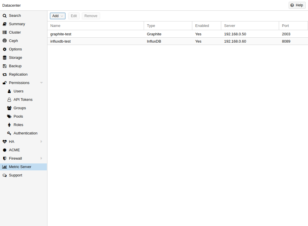
In Proxmox VE, you can define external metric servers, which will periodically receive various stats about your hosts, virtual guests and storages.
Currently supported are:
-
Graphite (see https://graphiteapp.org )
-
InfluxDB (see https://www.influxdata.com/time-series-platform/influxdb/ )
The external metric server definitions are saved in /etc/pve/status.cfg, and can be edited through the web interface.
3.6.1. Graphite server configuration
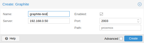
The default port is set to 2003 and the default graphite path is proxmox.
By default, Proxmox VE sends the data over UDP, so the graphite server has to be configured to accept this. Here the maximum transmission unit (MTU) can be configured for environments not using the standard 1500 MTU.
You can also configure the plugin to use TCP. In order not to block the important pvestatd statistic collection daemon, a timeout is required to cope with network problems.
3.6.2. Influxdb plugin configuration
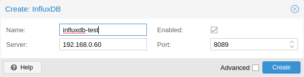
Proxmox VE sends the data over UDP, so the influxdb server has to be configured for this. The MTU can also be configured here, if necessary.
Here is an example configuration for influxdb (on your influxdb server):
[[udp]]
   enabled = true
   bind-address = "0.0.0.0:8089"
   database = "proxmox"
   batch-size = 1000
   batch-timeout = "1s"
With this configuration, your server listens on all IP addresses on port 8089, and writes the data in the proxmox database
Alternatively, the plugin can be configured to use the http(s) API of InfluxDB 2.x. InfluxDB 1.8.x does contain a forwards compatible API endpoint for this v2 API.
To use it, set influxdbproto to http or https (depending on your configuration). By default, Proxmox VE uses the organization proxmox and the bucket/db proxmox (They can be set with the configuration organization and bucket respectively).
Since InfluxDB’s v2 API is only available with authentication, you have to generate a token that can write into the correct bucket and set it.
In the v2 compatible API of 1.8.x, you can use user:password as token (if required), and can omit the organization since that has no meaning in InfluxDB 1.x.
You can also set the HTTP Timeout (default is 1s) with the timeout setting, as well as the maximum batch size (default 25000000 bytes) with the max-body-size setting (this corresponds to the InfluxDB setting with the same name).
3.7. Disk Health Monitoring
Although a robust and redundant storage is recommended, it can be very helpful to monitor the health of your local disks.
Starting with Proxmox VE 4.3, the package smartmontools
[smartmontools homepage https://www.smartmontools.org]
is installed and required. This is a set of tools to monitor and control
the S.M.A.R.T. system for local hard disks.
You can get the status of a disk by issuing the following command:
# smartctl -a /dev/sdX
where /dev/sdX is the path to one of your local disks.
If the output says:
SMART support is: Disabled
you can enable it with the command:
# smartctl -s on /dev/sdX
For more information on how to use smartctl, please see man smartctl.
By default, smartmontools daemon smartd is active and enabled, and scans the disks under /dev/sdX and /dev/hdX every 30 minutes for errors and warnings, and sends an e-mail to root if it detects a problem.
For more information about how to configure smartd, please see man smartd and man smartd.conf.
If you use your hard disks with a hardware raid controller, there are most likely tools to monitor the disks in the raid array and the array itself. For more information about this, please refer to the vendor of your raid controller.
3.8. Logical Volume Manager (LVM)
Most people install Proxmox VE directly on a local disk. The Proxmox VE installation CD offers several options for local disk management, and the current default setup uses LVM. The installer lets you select a single disk for such setup, and uses that disk as physical volume for the Volume Group (VG) pve. The following output is from a test installation using a small 8GB disk:
# pvs
  PV         VG   Fmt  Attr PSize PFree
  /dev/sda3  pve  lvm2 a--  7.87g 876.00m

# vgs
  VG   #PV #LV #SN Attr   VSize VFree
  pve    1   3   0 wz--n- 7.87g 876.00m
The installer allocates three Logical Volumes (LV) inside this VG:
# lvs
  LV   VG   Attr       LSize   Pool Origin Data%  Meta%
  data pve  twi-a-tz--   4.38g             0.00   0.63
  root pve  -wi-ao----   1.75g
  swap pve  -wi-ao---- 896.00m
- root
-
Formatted as ext4, and contains the operating system.
- swap
-
Swap partition
- data
-
This volume uses LVM-thin, and is used to store VM images. LVM-thin is preferable for this task, because it offers efficient support for snapshots and clones.
For Proxmox VE versions up to 4.1, the installer creates a standard logical volume called “data”, which is mounted at /var/lib/vz.
Starting from version 4.2, the logical volume “data” is a LVM-thin pool, used to store block based guest images, and /var/lib/vz is simply a directory on the root file system.
3.8.1. Hardware
We highly recommend to use a hardware RAID controller (with BBU) for such setups. This increases performance, provides redundancy, and make disk replacements easier (hot-pluggable).
LVM itself does not need any special hardware, and memory requirements are very low.
3.8.2. Bootloader
We install two boot loaders by default. The first partition contains the standard GRUB boot loader. The second partition is an EFI System Partition (ESP), which makes it possible to boot on EFI systems and to apply persistent firmware updates from the user space.
3.8.3. Creating a Volume Group
Let’s assume we have an empty disk /dev/sdb, onto which we want to create a volume group named “vmdata”.
|
|
Please note that the following commands will destroy all existing data on /dev/sdb. |
First create a partition.
# sgdisk -N 1 /dev/sdb
Create a Physical Volume (PV) without confirmation and 250K metadatasize.
# pvcreate --metadatasize 250k -y -ff /dev/sdb1
Create a volume group named “vmdata” on /dev/sdb1
# vgcreate vmdata /dev/sdb1
3.8.4. Creating an extra LV for /var/lib/vz
This can be easily done by creating a new thin LV.
# lvcreate -n <Name> -V <Size[M,G,T]> <VG>/<LVThin_pool>
A real world example:
# lvcreate -n vz -V 10G pve/data
Now a filesystem must be created on the LV.
# mkfs.ext4 /dev/pve/vz
At last this has to be mounted.
|
|
be sure that /var/lib/vz is empty. On a default installation it’s not. |
To make it always accessible add the following line in /etc/fstab.
# echo '/dev/pve/vz /var/lib/vz ext4 defaults 0 2' >> /etc/fstab
3.8.5. Resizing the thin pool
Resize the LV and the metadata pool with the following command:
# lvresize --size +<size[\M,G,T]> --poolmetadatasize +<size[\M,G]> <VG>/<LVThin_pool>
|
|
When extending the data pool, the metadata pool must also be extended. |
3.8.6. Create a LVM-thin pool
A thin pool has to be created on top of a volume group. How to create a volume group see Section LVM.
# lvcreate -L 80G -T -n vmstore vmdata
3.9. ZFS on Linux
ZFS is a combined file system and logical volume manager designed by Sun Microsystems. Starting with Proxmox VE 3.4, the native Linux kernel port of the ZFS file system is introduced as optional file system and also as an additional selection for the root file system. There is no need for manually compile ZFS modules - all packages are included.
By using ZFS, its possible to achieve maximum enterprise features with low budget hardware, but also high performance systems by leveraging SSD caching or even SSD only setups. ZFS can replace cost intense hardware raid cards by moderate CPU and memory load combined with easy management.
-
Easy configuration and management with Proxmox VE GUI and CLI.
-
Reliable
-
Protection against data corruption
-
Data compression on file system level
-
Snapshots
-
Copy-on-write clone
-
Various raid levels: RAID0, RAID1, RAID10, RAIDZ-1, RAIDZ-2, RAIDZ-3, dRAID, dRAID2, dRAID3
-
Can use SSD for cache
-
Self healing
-
Continuous integrity checking
-
Designed for high storage capacities
-
Asynchronous replication over network
-
Open Source
-
Encryption
-
…
3.9.1. Hardware
ZFS depends heavily on memory, so you need at least 8GB to start. In practice, use as much as you can get for your hardware/budget. To prevent data corruption, we recommend the use of high quality ECC RAM.
If you use a dedicated cache and/or log disk, you should use an enterprise class SSD. This can increase the overall performance significantly.
|
|
Do not use ZFS on top of a hardware RAID controller which has its own cache management. ZFS needs to communicate directly with the disks. An HBA adapter or something like an LSI controller flashed in “IT” mode is more appropriate. |
If you are experimenting with an installation of Proxmox VE inside a VM (Nested Virtualization), don’t use virtio for disks of that VM, as they are not supported by ZFS. Use IDE or SCSI instead (also works with the virtio SCSI controller type).
3.9.2. Installation as Root File System
When you install using the Proxmox VE installer, you can choose ZFS for the root file system. You need to select the RAID type at installation time:
|
RAID0
|
Also called “striping”. The capacity of such volume is the sum of the capacities of all disks. But RAID0 does not add any redundancy, so the failure of a single drive makes the volume unusable. |
|
RAID1
|
Also called “mirroring”. Data is written identically to all disks. This mode requires at least 2 disks with the same size. The resulting capacity is that of a single disk. |
|
RAID10
|
A combination of RAID0 and RAID1. Requires at least 4 disks. |
|
RAIDZ-1
|
A variation on RAID-5, single parity. Requires at least 3 disks. |
|
RAIDZ-2
|
A variation on RAID-5, double parity. Requires at least 4 disks. |
|
RAIDZ-3
|
A variation on RAID-5, triple parity. Requires at least 5 disks. |
The installer automatically partitions the disks, creates a ZFS pool called rpool, and installs the root file system on the ZFS subvolume rpool/ROOT/pve-1.
Another subvolume called rpool/data is created to store VM images. In order to use that with the Proxmox VE tools, the installer creates the following configuration entry in /etc/pve/storage.cfg:
zfspool: local-zfs
        pool rpool/data
        sparse
        content images,rootdir
After installation, you can view your ZFS pool status using the zpool command:
# zpool status
  pool: rpool
 state: ONLINE
  scan: none requested
config:

        NAME        STATE     READ WRITE CKSUM
        rpool       ONLINE       0     0     0
          mirror-0  ONLINE       0     0     0
            sda2    ONLINE       0     0     0
            sdb2    ONLINE       0     0     0
          mirror-1  ONLINE       0     0     0
            sdc     ONLINE       0     0     0
            sdd     ONLINE       0     0     0

errors: No known data errors
The zfs command is used to configure and manage your ZFS file systems. The following command lists all file systems after installation:
# zfs list
NAME               USED  AVAIL  REFER  MOUNTPOINT
rpool             4.94G  7.68T    96K  /rpool
rpool/ROOT         702M  7.68T    96K  /rpool/ROOT
rpool/ROOT/pve-1   702M  7.68T   702M  /
rpool/data          96K  7.68T    96K  /rpool/data
rpool/swap        4.25G  7.69T    64K  -
3.9.3. ZFS RAID Level Considerations
There are a few factors to take into consideration when choosing the layout of a ZFS pool. The basic building block of a ZFS pool is the virtual device, or vdev. All vdevs in a pool are used equally and the data is striped among them (RAID0). Check the zpoolconcepts(7) manpage for more details on vdevs.
Performance
Each vdev type has different performance behaviors. The two parameters of interest are the IOPS (Input/Output Operations per Second) and the bandwidth with which data can be written or read.
A mirror vdev (RAID1) will approximately behave like a single disk in regard to both parameters when writing data. When reading data the performance will scale linearly with the number of disks in the mirror.
A common situation is to have 4 disks. When setting it up as 2 mirror vdevs (RAID10) the pool will have the write characteristics as two single disks in regard to IOPS and bandwidth. For read operations it will resemble 4 single disks.
A RAIDZ of any redundancy level will approximately behave like a single disk in regard to IOPS with a lot of bandwidth. How much bandwidth depends on the size of the RAIDZ vdev and the redundancy level.
A dRAID pool should match the performance of an equivalent RAIDZ pool.
For running VMs, IOPS is the more important metric in most situations.
Size, Space usage and Redundancy
While a pool made of mirror vdevs will have the best performance characteristics, the usable space will be 50% of the disks available. Less if a mirror vdev consists of more than 2 disks, for example in a 3-way mirror. At least one healthy disk per mirror is needed for the pool to stay functional.
The usable space of a RAIDZ type vdev of N disks is roughly N-P, with P being the RAIDZ-level. The RAIDZ-level indicates how many arbitrary disks can fail without losing data. A special case is a 4 disk pool with RAIDZ2. In this situation it is usually better to use 2 mirror vdevs for the better performance as the usable space will be the same.
Another important factor when using any RAIDZ level is how ZVOL datasets, which are used for VM disks, behave. For each data block the pool needs parity data which is at least the size of the minimum block size defined by the ashift value of the pool. With an ashift of 12 the block size of the pool is 4k. The default block size for a ZVOL is 8k. Therefore, in a RAIDZ2 each 8k block written will cause two additional 4k parity blocks to be written, 8k + 4k + 4k = 16k. This is of course a simplified approach and the real situation will be slightly different with metadata, compression and such not being accounted for in this example.
This behavior can be observed when checking the following properties of the ZVOL:
-
volsize
-
refreservation (if the pool is not thin provisioned)
-
used (if the pool is thin provisioned and without snapshots present)
# zfs get volsize,refreservation,used <pool>/vm-<vmid>-disk-X
volsize is the size of the disk as it is presented to the VM, while refreservation shows the reserved space on the pool which includes the expected space needed for the parity data. If the pool is thin provisioned, the refreservation will be set to 0. Another way to observe the behavior is to compare the used disk space within the VM and the used property. Be aware that snapshots will skew the value.
There are a few options to counter the increased use of space:
-
Increase the volblocksize to improve the data to parity ratio
-
Use mirror vdevs instead of RAIDZ
-
Use ashift=9 (block size of 512 bytes)
The volblocksize property can only be set when creating a ZVOL. The default value can be changed in the storage configuration. When doing this, the guest needs to be tuned accordingly and depending on the use case, the problem of write amplification is just moved from the ZFS layer up to the guest.
Using ashift=9 when creating the pool can lead to bad performance, depending on the disks underneath, and cannot be changed later on.
Mirror vdevs (RAID1, RAID10) have favorable behavior for VM workloads. Use them, unless your environment has specific needs and characteristics where RAIDZ performance characteristics are acceptable.
3.9.4. ZFS dRAID
In a ZFS dRAID (declustered RAID) the hot spare drive(s) participate in the RAID.
Their spare capacity is reserved and used for rebuilding when one drive fails.
This provides, depending on the configuration, faster rebuilding compared to a
RAIDZ in case of drive failure. More information can be found in the official
OpenZFS documentation.
[OpenZFS dRAID
https://openzfs.github.io/openzfs-docs/Basic%20Concepts/dRAID%20Howto.html]
|
|
dRAID is intended for more than 10-15 disks in a dRAID. A RAIDZ setup should be better for a lower amount of disks in most use cases. |
|
|
The GUI requires one more disk than the minimum (i.e. dRAID1 needs 3). It expects that a spare disk is added as well. |
-
dRAID1 or dRAID: requires at least 2 disks, one can fail before data is lost
-
dRAID2: requires at least 3 disks, two can fail before data is lost
-
dRAID3: requires at least 4 disks, three can fail before data is lost
Additional information can be found on the manual page:
# man zpoolconcepts
Spares and Data
The number of spares tells the system how many disks it should keep ready in case of a disk failure. The default value is 0 spares. Without spares, rebuilding won’t get any speed benefits.
data defines the number of devices in a redundancy group. The default value is 8. Except when disks - parity - spares equal something less than 8, the lower number is used. In general, a smaller number of data devices leads to higher IOPS, better compression ratios and faster resilvering, but defining fewer data devices reduces the available storage capacity of the pool.
3.9.5. Bootloader
Proxmox VE uses proxmox-boot-tool to manage the bootloader configuration. See the chapter on Proxmox VE host bootloaders for details.
3.9.6. ZFS Administration
This section gives you some usage examples for common tasks. ZFS itself is really powerful and provides many options. The main commands to manage ZFS are zfs and zpool. Both commands come with great manual pages, which can be read with:
# man zpool
# man zfs
Create a new zpool
To create a new pool, at least one disk is needed. The ashift should have the same sector-size (2 power of ashift) or larger as the underlying disk.
# zpool create -f -o ashift=12 <pool> <device>
|
|
Pool names must adhere to the following rules:
|
To activate compression (see section Compression in ZFS):
# zfs set compression=lz4 <pool>
Create a new pool with RAID-0
Minimum 1 disk
# zpool create -f -o ashift=12 <pool> <device1> <device2>
Create a new pool with RAID-1
Minimum 2 disks
# zpool create -f -o ashift=12 <pool> mirror <device1> <device2>
Create a new pool with RAID-10
Minimum 4 disks
# zpool create -f -o ashift=12 <pool> mirror <device1> <device2> mirror <device3> <device4>
Create a new pool with RAIDZ-1
Minimum 3 disks
# zpool create -f -o ashift=12 <pool> raidz1 <device1> <device2> <device3>
Create a new pool with RAIDZ-2
Minimum 4 disks
# zpool create -f -o ashift=12 <pool> raidz2 <device1> <device2> <device3> <device4>
Please read the section for ZFS RAID Level Considerations to get a rough estimate on how IOPS and bandwidth expectations before setting up a pool, especially when wanting to use a RAID-Z mode.
Create a new pool with cache (L2ARC)
It is possible to use a dedicated device, or partition, as second-level cache to increase the performance. Such a cache device will especially help with random-read workloads of data that is mostly static. As it acts as additional caching layer between the actual storage, and the in-memory ARC, it can also help if the ARC must be reduced due to memory constraints.
# zpool create -f -o ashift=12 <pool> <device> cache <cache-device>
Here only a single <device> and a single <cache-device> was used, but it is possible to use more devices, like it’s shown in Create a new pool with RAID.
Note that for cache devices no mirror or raid modi exist, they are all simply accumulated.
If any cache device produces errors on read, ZFS will transparently divert that request to the underlying storage layer.
Create a new pool with log (ZIL)
It is possible to use a dedicated drive, or partition, for the ZFS Intent Log (ZIL), it is mainly used to provide safe synchronous transactions, so often in performance critical paths like databases, or other programs that issue fsync operations more frequently.
The pool is used as default ZIL location, diverting the ZIL IO load to a separate device can, help to reduce transaction latencies while relieving the main pool at the same time, increasing overall performance.
For disks to be used as log devices, directly or through a partition, it’s recommend to:
-
use fast SSDs with power-loss protection, as those have much smaller commit latencies.
-
Use at least a few GB for the partition (or whole device), but using more than half of your installed memory won’t provide you with any real advantage.
# zpool create -f -o ashift=12 <pool> <device> log <log-device>
In above example a single <device> and a single <log-device> is used, but you can also combine this with other RAID variants, as described in the Create a new pool with RAID section.
You can also mirror the log device to multiple devices, this is mainly useful to ensure that performance doesn’t immediately degrades if a single log device fails.
If all log devices fail the ZFS main pool itself will be used again, until the log device(s) get replaced.
Add cache and log to an existing pool
If you have a pool without cache and log you can still add both, or just one of them, at any time.
For example, let’s assume you got a good enterprise SSD with power-loss protection that you want to use for improving the overall performance of your pool.
As the maximum size of a log device should be about half the size of the installed physical memory, it means that the ZIL will mostly likely only take up a relatively small part of the SSD, the remaining space can be used as cache.
First you have to create two GPT partitions on the SSD with parted or gdisk.
Then you’re ready to add them to an pool:
# zpool add -f <pool> log <device-part1> cache <device-part2>
Just replay <pool>, <device-part1> and <device-part2> with the pool name and the two /dev/disk/by-id/ paths to the partitions.
You can also add ZIL and cache separately.
# zpool add <pool> log <log-device>
Changing a failed device
# zpool replace -f <pool> <old-device> <new-device>
Depending on how Proxmox VE was installed it is either using systemd-boot or GRUB
through proxmox-boot-tool
[Systems installed with Proxmox VE 6.4 or later,
EFI systems installed with Proxmox VE 5.4 or later]
or plain GRUB as bootloader (see
Host Bootloader). You can check by running:
# proxmox-boot-tool status
The first steps of copying the partition table, reissuing GUIDs and replacing the ZFS partition are the same. To make the system bootable from the new disk, different steps are needed which depend on the bootloader in use.
# sgdisk <healthy bootable device> -R <new device>
# sgdisk -G <new device>
# zpool replace -f <pool> <old zfs partition> <new zfs partition>
|
|
Use the zpool status -v command to monitor how far the resilvering process of the new disk has progressed. |
# proxmox-boot-tool format <new disk's ESP>
# proxmox-boot-tool init <new disk's ESP> [grub]
|
|
ESP stands for EFI System Partition, which is setup as partition #2 on bootable disks setup by the Proxmox VE installer since version 5.4. For details, see Setting up a new partition for use as synced ESP. |
|
|
Make sure to pass grub as mode to proxmox-boot-tool init if proxmox-boot-tool status indicates your current disks are using GRUB, especially if Secure Boot is enabled! |
# grub-install <new disk>
|
|
Plain GRUB is only used on systems installed with Proxmox VE 6.3 or earlier, which have not been manually migrated to using proxmox-boot-tool yet. |
3.9.7. Configure E-Mail Notification
ZFS comes with an event daemon ZED, which monitors events generated by the ZFS kernel module. The daemon can also send emails on ZFS events like pool errors. Newer ZFS packages ship the daemon in a separate zfs-zed package, which should already be installed by default in Proxmox VE.
You can configure the daemon via the file /etc/zfs/zed.d/zed.rc with your favorite editor. The required setting for email notification is ZED_EMAIL_ADDR, which is set to root by default.
ZED_EMAIL_ADDR="root"
Please note Proxmox VE forwards mails to root to the email address configured for the root user.
3.9.8. Limit ZFS Memory Usage
ZFS uses 50 % of the host memory for the Adaptive Replacement Cache (ARC) by default. For new installations starting with Proxmox VE 8.1, the ARC usage limit will be set to 10 % of the installed physical memory, clamped to a maximum of 16 GiB. This value is written to /etc/modprobe.d/zfs.conf.
Allocating enough memory for the ARC is crucial for IO performance, so reduce it with caution. As a general rule of thumb, allocate at least 2 GiB Base + 1 GiB/TiB-Storage. For example, if you have a pool with 8 TiB of available storage space then you should use 10 GiB of memory for the ARC.
ZFS also enforces a minimum value of 64 MiB.
You can change the ARC usage limit for the current boot (a reboot resets this change again) by writing to the zfs_arc_max module parameter directly:
echo "$[10 * 1024*1024*1024]" >/sys/module/zfs/parameters/zfs_arc_max
To permanently change the ARC limits, add (or change if already present) the following line to /etc/modprobe.d/zfs.conf:
options zfs zfs_arc_max=8589934592
This example setting limits the usage to 8 GiB (8 * 230).
|
|
In case your desired zfs_arc_max value is lower than or equal to zfs_arc_min (which defaults to 1/32 of the system memory), zfs_arc_max will be ignored unless you also set zfs_arc_min to at most zfs_arc_max - 1. |
echo "$[8 * 1024*1024*1024 - 1]" >/sys/module/zfs/parameters/zfs_arc_min
echo "$[8 * 1024*1024*1024]" >/sys/module/zfs/parameters/zfs_arc_max
This example setting (temporarily) limits the usage to 8 GiB (8 * 230) on systems with more than 256 GiB of total memory, where simply setting zfs_arc_max alone would not work.
|
|
If your root file system is ZFS, you must update your initramfs every time this value changes: # update-initramfs -u -k all You must reboot to activate these changes. |
3.9.9. SWAP on ZFS
Swap-space created on a zvol may generate some troubles, like blocking the server or generating a high IO load, often seen when starting a Backup to an external Storage.
We strongly recommend to use enough memory, so that you normally do not run into low memory situations. Should you need or want to add swap, it is preferred to create a partition on a physical disk and use it as a swap device. You can leave some space free for this purpose in the advanced options of the installer. Additionally, you can lower the “swappiness” value. A good value for servers is 10:
# sysctl -w vm.swappiness=10
To make the swappiness persistent, open /etc/sysctl.conf with an editor of your choice and add the following line:
vm.swappiness = 10
| Value | Strategy |
|---|---|
vm.swappiness = 0 |
The kernel will swap only to avoid an out of memory condition |
vm.swappiness = 1 |
Minimum amount of swapping without disabling it entirely. |
vm.swappiness = 10 |
This value is sometimes recommended to improve performance when sufficient memory exists in a system. |
vm.swappiness = 60 |
The default value. |
vm.swappiness = 100 |
The kernel will swap aggressively. |
3.9.10. Encrypted ZFS Datasets
|
|
Native ZFS encryption in Proxmox VE is experimental. Known limitations and
issues include Replication with encrypted datasets
[https://bugzilla.proxmox.com/show_bug.cgi?id=2350] , as well as checksum errors when using Snapshots or ZVOLs. [https://github.com/openzfs/zfs/issues/11688] |
ZFS on Linux version 0.8.0 introduced support for native encryption of datasets. After an upgrade from previous ZFS on Linux versions, the encryption feature can be enabled per pool:
# zpool get feature@encryption tank
NAME  PROPERTY            VALUE            SOURCE
tank  feature@encryption  disabled         local

# zpool set feature@encryption=enabled

# zpool get feature@encryption tank
NAME  PROPERTY            VALUE            SOURCE
tank  feature@encryption  enabled         local
|
|
There is currently no support for booting from pools with encrypted datasets using GRUB, and only limited support for automatically unlocking encrypted datasets on boot. Older versions of ZFS without encryption support will not be able to decrypt stored data. |
|
|
It is recommended to either unlock storage datasets manually after booting, or to write a custom unit to pass the key material needed for unlocking on boot to zfs load-key. |
|
|
Establish and test a backup procedure before enabling encryption of production data. If the associated key material/passphrase/keyfile has been lost, accessing the encrypted data is no longer possible. |
Encryption needs to be setup when creating datasets/zvols, and is inherited by default to child datasets. For example, to create an encrypted dataset tank/encrypted_data and configure it as storage in Proxmox VE, run the following commands:
# zfs create -o encryption=on -o keyformat=passphrase tank/encrypted_data
Enter passphrase:
Re-enter passphrase:

# pvesm add zfspool encrypted_zfs -pool tank/encrypted_data
All guest volumes/disks create on this storage will be encrypted with the shared key material of the parent dataset.
To actually use the storage, the associated key material needs to be loaded and the dataset needs to be mounted. This can be done in one step with:
# zfs mount -l tank/encrypted_data
Enter passphrase for 'tank/encrypted_data':
It is also possible to use a (random) keyfile instead of prompting for a passphrase by setting the keylocation and keyformat properties, either at creation time or with zfs change-key on existing datasets:
# dd if=/dev/urandom of=/path/to/keyfile bs=32 count=1

# zfs change-key -o keyformat=raw -o keylocation=file:///path/to/keyfile tank/encrypted_data
|
|
When using a keyfile, special care needs to be taken to secure the keyfile against unauthorized access or accidental loss. Without the keyfile, it is not possible to access the plaintext data! |
A guest volume created underneath an encrypted dataset will have its encryptionroot property set accordingly. The key material only needs to be loaded once per encryptionroot to be available to all encrypted datasets underneath it.
See the encryptionroot, encryption, keylocation, keyformat and keystatus properties, the zfs load-key, zfs unload-key and zfs change-key commands and the Encryption section from man zfs for more details and advanced usage.
3.9.11. Compression in ZFS
When compression is enabled on a dataset, ZFS tries to compress all new blocks before writing them and decompresses them on reading. Already existing data will not be compressed retroactively.
You can enable compression with:
# zfs set compression=<algorithm> <dataset>
We recommend using the lz4 algorithm, because it adds very little CPU overhead. Other algorithms like lzjb and gzip-N, where N is an integer from 1 (fastest) to 9 (best compression ratio), are also available. Depending on the algorithm and how compressible the data is, having compression enabled can even increase I/O performance.
You can disable compression at any time with:
# zfs set compression=off <dataset>
Again, only new blocks will be affected by this change.
3.9.12. ZFS Special Device
Since version 0.8.0 ZFS supports special devices. A special device in a pool is used to store metadata, deduplication tables, and optionally small file blocks.
A special device can improve the speed of a pool consisting of slow spinning hard disks with a lot of metadata changes. For example workloads that involve creating, updating or deleting a large number of files will benefit from the presence of a special device. ZFS datasets can also be configured to store whole small files on the special device which can further improve the performance. Use fast SSDs for the special device.
|
|
The redundancy of the special device should match the one of the pool, since the special device is a point of failure for the whole pool. |
|
|
Adding a special device to a pool cannot be undone! |
# zpool create -f -o ashift=12 <pool> mirror <device1> <device2> special mirror <device3> <device4>
# zpool add <pool> special mirror <device1> <device2>
ZFS datasets expose the special_small_blocks=<size> property. size can be 0 to disable storing small file blocks on the special device or a power of two in the range between 512B to 1M. After setting the property new file blocks smaller than size will be allocated on the special device.
|
|
If the value for special_small_blocks is greater than or equal to the recordsize (default 128K) of the dataset, all data will be written to the special device, so be careful! |
Setting the special_small_blocks property on a pool will change the default value of that property for all child ZFS datasets (for example all containers in the pool will opt in for small file blocks).
# zfs set special_small_blocks=4K <pool>
# zfs set special_small_blocks=4K <pool>/<filesystem>
# zfs set special_small_blocks=0 <pool>/<filesystem>
3.9.13. ZFS Pool Features
Changes to the on-disk format in ZFS are only made between major version changes and are specified through features. All features, as well as the general mechanism are well documented in the zpool-features(5) manpage.
Since enabling new features can render a pool not importable by an older version of ZFS, this needs to be done actively by the administrator, by running zpool upgrade on the pool (see the zpool-upgrade(8) manpage).
Unless you need to use one of the new features, there is no upside to enabling them.
In fact, there are some downsides to enabling new features:
-
A system with root on ZFS, that still boots using GRUB will become unbootable if a new feature is active on the rpool, due to the incompatible implementation of ZFS in GRUB.
-
The system will not be able to import any upgraded pool when booted with an older kernel, which still ships with the old ZFS modules.
-
Booting an older Proxmox VE ISO to repair a non-booting system will likewise not work.
|
|
Do not upgrade your rpool if your system is still booted with GRUB, as this will render your system unbootable. This includes systems installed before Proxmox VE 5.4, and systems booting with legacy BIOS boot (see how to determine the bootloader). |
# zpool upgrade <pool>
3.10. BTRFS
|
|
BTRFS integration is currently a technology preview in Proxmox VE. |
BTRFS is a modern copy on write file system natively supported by the Linux kernel, implementing features such as snapshots, built-in RAID and self healing via checksums for data and metadata. Starting with Proxmox VE 7.0, BTRFS is introduced as optional selection for the root file system.
-
Main system setup almost identical to the traditional ext4 based setup
-
Snapshots
-
Data compression on file system level
-
Copy-on-write clone
-
RAID0, RAID1 and RAID10
-
Protection against data corruption
-
Self healing
-
natively supported by the Linux kernel
-
…
-
RAID levels 5/6 are experimental and dangerous
3.10.1. Installation as Root File System
When you install using the Proxmox VE installer, you can choose BTRFS for the root file system. You need to select the RAID type at installation time:
|
RAID0
|
Also called “striping”. The capacity of such volume is the sum of the capacities of all disks. But RAID0 does not add any redundancy, so the failure of a single drive makes the volume unusable. |
|
RAID1
|
Also called “mirroring”. Data is written identically to all disks. This mode requires at least 2 disks with the same size. The resulting capacity is that of a single disk. |
|
RAID10
|
A combination of RAID0 and RAID1. Requires at least 4 disks. |
The installer automatically partitions the disks and creates an additional subvolume at /var/lib/pve/local-btrfs. In order to use that with the Proxmox VE tools, the installer creates the following configuration entry in /etc/pve/storage.cfg:
dir: local
        path /var/lib/vz
        content iso,vztmpl,backup
        disable

btrfs: local-btrfs
        path /var/lib/pve/local-btrfs
        content iso,vztmpl,backup,images,rootdir
This explicitly disables the default local storage in favor of a BTRFS specific storage entry on the additional subvolume.
The btrfs command is used to configure and manage the BTRFS file system, After the installation, the following command lists all additional subvolumes:
# btrfs subvolume list /
ID 256 gen 6 top level 5 path var/lib/pve/local-btrfs
3.10.2. BTRFS Administration
This section gives you some usage examples for common tasks.
Creating a BTRFS file system
To create BTRFS file systems, mkfs.btrfs is used. The -d and -m parameters are used to set the profile for metadata and data respectively. With the optional -L parameter, a label can be set.
Generally, the following modes are supported: single, raid0, raid1, raid10.
Create a BTRFS file system on a single disk /dev/sdb with the label My-Storage:
# mkfs.btrfs -m single -d single -L My-Storage /dev/sdb
Or create a RAID1 on the two partitions /dev/sdb1 and /dev/sdc1:
# mkfs.btrfs -m raid1 -d raid1 -L My-Storage /dev/sdb1 /dev/sdc1
Mounting a BTRFS file system
The new file-system can then be mounted either manually, for example:
 # mkdir /my-storage
 # mount /dev/sdb /my-storage
A BTRFS can also be added to /etc/fstab like any other mount point, automatically mounting it on boot. It’s recommended to avoid using block-device paths but use the UUID value the mkfs.btrfs command printed, especially there is more than one disk in a BTRFS setup.
For example:
# ... other mount points left out for brevity

# using the UUID from the mkfs.btrfs output is highly recommended
UUID=e2c0c3ff-2114-4f54-b767-3a203e49f6f3 /my-storage btrfs defaults 0 0
|
|
If you do not have the UUID available anymore you can use the blkid tool to list all properties of block-devices. |
Afterwards you can trigger the first mount by executing:
mount /my-storage
After the next reboot this will be automatically done by the system at boot.
Adding a BTRFS file system to Proxmox VE
You can add an existing BTRFS file system to Proxmox VE via the web interface, or using the CLI, for example:
pvesm add btrfs my-storage --path /my-storage
Creating a subvolume
Creating a subvolume links it to a path in the BTRFS file system, where it will appear as a regular directory.
# btrfs subvolume create /some/path
Afterwards /some/path will act like a regular directory.
Deleting a subvolume
Contrary to directories removed via rmdir, subvolumes do not need to be empty in order to be deleted via the btrfs command.
# btrfs subvolume delete /some/path
Creating a snapshot of a subvolume
BTRFS does not actually distinguish between snapshots and normal subvolumes, so taking a snapshot can also be seen as creating an arbitrary copy of a subvolume. By convention, Proxmox VE will use the read-only flag when creating snapshots of guest disks or subvolumes, but this flag can also be changed later on.
# btrfs subvolume snapshot -r /some/path /a/new/path
This will create a read-only "clone" of the subvolume on /some/path at /a/new/path. Any future modifications to /some/path cause the modified data to be copied before modification.
If the read-only (-r) option is left out, both subvolumes will be writable.
Enabling compression
By default, BTRFS does not compress data. To enable compression, the compress mount option can be added. Note that data already written will not be compressed after the fact.
By default, the rootfs will be listed in /etc/fstab as follows:
UUID=<uuid of your root file system> / btrfs defaults 0 1
You can simply append compress=zstd, compress=lzo, or compress=zlib to the defaults above like so:
UUID=<uuid of your root file system> / btrfs defaults,compress=zstd 0 1
This change will take effect after rebooting.
Checking Space Usage
The classic df tool may output confusing values for some BTRFS setups. For a better estimate use the btrfs filesystem usage /PATH command, for example:
# btrfs fi usage /my-storage
3.11. Proxmox Node Management
The Proxmox VE node management tool (pvenode) allows you to control node specific settings and resources.
Currently pvenode allows you to set a node’s description, run various bulk operations on the node’s guests, view the node’s task history, and manage the node’s SSL certificates, which are used for the API and the web GUI through pveproxy.
3.11.1. Wake-on-LAN
Wake-on-LAN (WoL) allows you to switch on a sleeping computer in the network, by sending a magic packet. At least one NIC must support this feature, and the respective option needs to be enabled in the computer’s firmware (BIOS/UEFI) configuration. The option name can vary from Enable Wake-on-Lan to Power On By PCIE Device; check your motherboard’s vendor manual, if you’re unsure. ethtool can be used to check the WoL configuration of <interface> by running:
ethtool <interface> | grep Wake-on
pvenode allows you to wake sleeping members of a cluster via WoL, using the command:
pvenode wakeonlan <node>
This broadcasts the WoL magic packet on UDP port 9, containing the MAC address of <node> obtained from the wakeonlan property. The node-specific wakeonlan property can be set using the following command:
pvenode config set -wakeonlan XX:XX:XX:XX:XX:XX
The interface via which to send the WoL packet is determined from the default route. It can be overwritten by setting the bind-interface via the following command:
pvenode config set -wakeonlan XX:XX:XX:XX:XX:XX,bind-interface=<iface-name>
The broadcast address (default 255.255.255.255) used when sending the WoL packet can further be changed by setting the broadcast-address explicitly using the following command:
pvenode config set -wakeonlan XX:XX:XX:XX:XX:XX,broadcast-address=<broadcast-address>
3.11.2. Task History
When troubleshooting server issues, for example, failed backup jobs, it can often be helpful to have a log of the previously run tasks. With Proxmox VE, you can access the nodes’s task history through the pvenode task command.
You can get a filtered list of a node’s finished tasks with the list subcommand. For example, to get a list of tasks related to VM 100 that ended with an error, the command would be:
pvenode task list --errors --vmid 100
The log of a task can then be printed using its UPID:
pvenode task log UPID:pve1:00010D94:001CA6EA:6124E1B9:vzdump:100:root@pam:
3.11.3. Bulk Guest Power Management
In case you have many VMs/containers, starting and stopping guests can be carried out in bulk operations with the startall and stopall subcommands of pvenode. By default, pvenode startall will only start VMs/containers which have been set to automatically start on boot (see Automatic Start and Shutdown of Virtual Machines), however, you can override this behavior with the --force flag. Both commands also have a --vms option, which limits the stopped/started guests to the specified VMIDs.
For example, to start VMs 100, 101, and 102, regardless of whether they have onboot set, you can use:
pvenode startall --vms 100,101,102 --force
To stop these guests (and any other guests that may be running), use the command:
pvenode stopall
|
|
The stopall command first attempts to perform a clean shutdown and then waits until either all guests have successfully shut down or an overridable timeout (3 minutes by default) has expired. Once that happens and the force-stop parameter is not explicitly set to 0 (false), all virtual guests that are still running are hard stopped. |
3.11.4. First Guest Boot Delay
In case your VMs/containers rely on slow-to-start external resources, for example an NFS server, you can also set a per-node delay between the time Proxmox VE boots and the time the first VM/container that is configured to autostart boots (see Automatic Start and Shutdown of Virtual Machines).
You can achieve this by setting the following (where 10 represents the delay in seconds):
pvenode config set --startall-onboot-delay 10
3.11.5. Bulk Guest Migration
In case an upgrade situation requires you to migrate all of your guests from one node to another, pvenode also offers the migrateall subcommand for bulk migration. By default, this command will migrate every guest on the system to the target node. It can however be set to only migrate a set of guests.
For example, to migrate VMs 100, 101, and 102, to the node pve2, with live-migration for local disks enabled, you can run:
pvenode migrateall pve2 --vms 100,101,102 --with-local-disks
3.12. Certificate Management
3.12.1. Certificates for Intra-Cluster Communication
Each Proxmox VE cluster creates by default its own (self-signed) Certificate Authority (CA) and generates a certificate for each node which gets signed by the aforementioned CA. These certificates are used for encrypted communication with the cluster’s pveproxy service and the Shell/Console feature if SPICE is used.
The CA certificate and key are stored in the Proxmox Cluster File System (pmxcfs).
3.12.2. Certificates for API and Web GUI
The REST API and web GUI are provided by the pveproxy service, which runs on each node.
You have the following options for the certificate used by pveproxy:
-
By default the node-specific certificate in /etc/pve/nodes/NODENAME/pve-ssl.pem is used. This certificate is signed by the cluster CA and therefore not automatically trusted by browsers and operating systems.
-
use an externally provided certificate (e.g. signed by a commercial CA).
-
use ACME (Let’s Encrypt) to get a trusted certificate with automatic renewal, this is also integrated in the Proxmox VE API and web interface.
For options 2 and 3 the file /etc/pve/local/pveproxy-ssl.pem (and /etc/pve/local/pveproxy-ssl.key, which needs to be without password) is used.
|
|
Keep in mind that /etc/pve/local is a node specific symlink to /etc/pve/nodes/NODENAME. |
Certificates are managed with the Proxmox VE Node management command (see the pvenode(1) manpage).
|
|
Do not replace or manually modify the automatically generated node certificate files in /etc/pve/local/pve-ssl.pem and /etc/pve/local/pve-ssl.key or the cluster CA files in /etc/pve/pve-root-ca.pem and /etc/pve/priv/pve-root-ca.key. |
3.12.3. Upload Custom Certificate
If you already have a certificate which you want to use for a Proxmox VE node you can upload that certificate simply over the web interface.
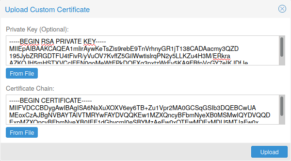
Note that the certificates key file, if provided, mustn’t be password protected.
3.12.4. Trusted certificates via Let’s Encrypt (ACME)
Proxmox VE includes an implementation of the Automatic Certificate Management Environment ACME protocol, allowing Proxmox VE admins to use an ACME provider like Let’s Encrypt for easy setup of TLS certificates which are accepted and trusted on modern operating systems and web browsers out of the box.
Currently, the two ACME endpoints implemented are the Let’s Encrypt (LE) production and its staging environment. Our ACME client supports validation of http-01 challenges using a built-in web server and validation of dns-01 challenges using a DNS plugin supporting all the DNS API endpoints acme.sh does.
ACME Account
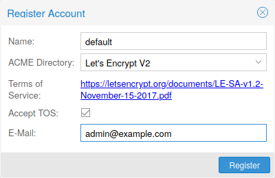
You need to register an ACME account per cluster with the endpoint you want to use. The email address used for that account will serve as contact point for renewal-due or similar notifications from the ACME endpoint.
You can register and deactivate ACME accounts over the web interface Datacenter -> ACME or using the pvenode command-line tool.
pvenode acme account register account-name mail@example.com
|
|
Because of rate-limits you should use LE staging for experiments or if you use ACME for the first time. |
ACME Plugins
The ACME plugins task is to provide automatic verification that you, and thus the Proxmox VE cluster under your operation, are the real owner of a domain. This is the basis building block for automatic certificate management.
The ACME protocol specifies different types of challenges, for example the http-01 where a web server provides a file with a certain content to prove that it controls a domain. Sometimes this isn’t possible, either because of technical limitations or if the address of a record to is not reachable from the public internet. The dns-01 challenge can be used in these cases. This challenge is fulfilled by creating a certain DNS record in the domain’s zone.
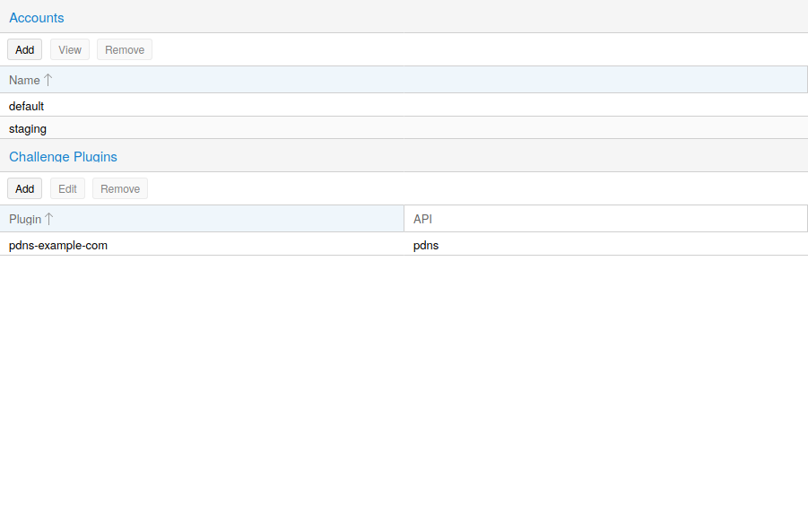
Proxmox VE supports both of those challenge types out of the box, you can configure plugins either over the web interface under Datacenter -> ACME, or using the pvenode acme plugin add command.
ACME Plugin configurations are stored in /etc/pve/priv/acme/plugins.cfg. A plugin is available for all nodes in the cluster.
Node Domains
Each domain is node specific. You can add new or manage existing domain entries under Node -> Certificates, or using the pvenode config command.
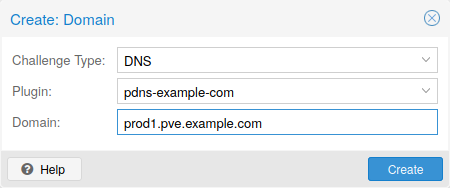
After configuring the desired domain(s) for a node and ensuring that the desired ACME account is selected, you can order your new certificate over the web interface. On success the interface will reload after 10 seconds.
Renewal will happen automatically.
3.12.5. ACME HTTP Challenge Plugin
There is always an implicitly configured standalone plugin for validating http-01 challenges via the built-in webserver spawned on port 80.
|
|
The name standalone means that it can provide the validation on it’s own, without any third party service. So, this plugin works also for cluster nodes. |
There are a few prerequisites to use it for certificate management with Let’s Encrypts ACME.
-
You have to accept the ToS of Let’s Encrypt to register an account.
-
Port 80 of the node needs to be reachable from the internet.
-
There must be no other listener on port 80.
-
The requested (sub)domain needs to resolve to a public IP of the Node.
3.12.6. ACME DNS API Challenge Plugin
On systems where external access for validation via the http-01 method is not possible or desired, it is possible to use the dns-01 validation method. This validation method requires a DNS server that allows provisioning of TXT records via an API.
Configuring ACME DNS APIs for validation
Proxmox VE re-uses the DNS plugins developed for the acme.sh
[acme.sh https://github.com/acmesh-official/acme.sh]
project, please
refer to its documentation for details on configuration of specific APIs.
The easiest way to configure a new plugin with the DNS API is using the web interface (Datacenter -> ACME).
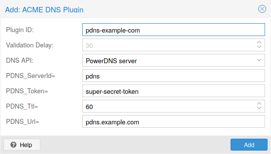
Choose DNS as challenge type. Then you can select your API provider, enter the credential data to access your account over their API.
|
|
See the acme.sh How to use DNS API wiki for more detailed information about getting API credentials for your provider. |
As there are many DNS providers and API endpoints Proxmox VE automatically generates the form for the credentials for some providers. For the others you will see a bigger text area, simply copy all the credentials KEY=VALUE pairs in there.
DNS Validation through CNAME Alias
A special alias mode can be used to handle the validation on a different domain/DNS server, in case your primary/real DNS does not support provisioning via an API. Manually set up a permanent CNAME record for _acme-challenge.domain1.example pointing to _acme-challenge.domain2.example and set the alias property in the Proxmox VE node configuration file to domain2.example to allow the DNS server of domain2.example to validate all challenges for domain1.example.
Combination of Plugins
Combining http-01 and dns-01 validation is possible in case your node is reachable via multiple domains with different requirements / DNS provisioning capabilities. Mixing DNS APIs from multiple providers or instances is also possible by specifying different plugin instances per domain.
|
|
Accessing the same service over multiple domains increases complexity and should be avoided if possible. |
3.12.7. Automatic renewal of ACME certificates
If a node has been successfully configured with an ACME-provided certificate (either via pvenode or via the GUI), the certificate will be automatically renewed by the pve-daily-update.service. Currently, renewal will be attempted if the certificate has expired already, or will expire in the next 30 days.
3.12.8. ACME Examples with pvenode
Example: Sample pvenode invocation for using Let’s Encrypt certificates
root@proxmox:~# pvenode acme account register default mail@example.invalid
Directory endpoints:
0) Let's Encrypt V2 (https://acme-v02.api.letsencrypt.org/directory)
1) Let's Encrypt V2 Staging (https://acme-staging-v02.api.letsencrypt.org/directory)
2) Custom
Enter selection: 1

Terms of Service: https://letsencrypt.org/documents/LE-SA-v1.2-November-15-2017.pdf
Do you agree to the above terms? [y|N]y
...
Task OK
root@proxmox:~# pvenode config set --acme domains=example.invalid
root@proxmox:~# pvenode acme cert order
Loading ACME account details
Placing ACME order
...
Status is 'valid'!

All domains validated!
...
Downloading certificate
Setting pveproxy certificate and key
Restarting pveproxy
Task OK
Example: Setting up the OVH API for validating a domain
|
|
the account registration steps are the same no matter which plugins are used, and are not repeated here. |
|
|
OVH_AK and OVH_AS need to be obtained from OVH according to the OVH API documentation |
First you need to get all information so you and Proxmox VE can access the API.
root@proxmox:~# cat /path/to/api-token
OVH_AK=XXXXXXXXXXXXXXXX
OVH_AS=YYYYYYYYYYYYYYYYYYYYYYYYYYYYYYYY
root@proxmox:~# source /path/to/api-token
root@proxmox:~# curl -XPOST -H"X-Ovh-Application: $OVH_AK" -H "Content-type: application/json" \
https://eu.api.ovh.com/1.0/auth/credential  -d '{
  "accessRules": [
    {"method": "GET","path": "/auth/time"},
    {"method": "GET","path": "/domain"},
    {"method": "GET","path": "/domain/zone/*"},
    {"method": "GET","path": "/domain/zone/*/record"},
    {"method": "POST","path": "/domain/zone/*/record"},
    {"method": "POST","path": "/domain/zone/*/refresh"},
    {"method": "PUT","path": "/domain/zone/*/record/"},
    {"method": "DELETE","path": "/domain/zone/*/record/*"}
]
}'
{"consumerKey":"ZZZZZZZZZZZZZZZZZZZZZZZZZZZZZZZZ","state":"pendingValidation","validationUrl":"https://eu.api.ovh.com/auth/?credentialToken=AAAAAAAAAAAAAAAAAAAAAAAAAAAAAAAAAAAAAAAAAAAAAAAAAAAAAAAAAAAAAAAA"}

(open validation URL and follow instructions to link Application Key with account/Consumer Key)

root@proxmox:~# echo "OVH_CK=ZZZZZZZZZZZZZZZZZZZZZZZZZZZZZZZZ" >> /path/to/api-token
Now you can setup the the ACME plugin:
root@proxmox:~# pvenode acme plugin add dns example_plugin --api ovh --data /path/to/api_token
root@proxmox:~# pvenode acme plugin config example_plugin
┌────────┬──────────────────────────────────────────┐
│ key    │ value                                    │
╞════════╪══════════════════════════════════════════╡
│ api    │ ovh                                      │
├────────┼──────────────────────────────────────────┤
│ data   │ OVH_AK=XXXXXXXXXXXXXXXX                  │
│        │ OVH_AS=YYYYYYYYYYYYYYYYYYYYYYYYYYYYYYYY  │
│        │ OVH_CK=ZZZZZZZZZZZZZZZZZZZZZZZZZZZZZZZZ  │
├────────┼──────────────────────────────────────────┤
│ digest │ 867fcf556363ca1bea866863093fcab83edf47a1 │
├────────┼──────────────────────────────────────────┤
│ plugin │ example_plugin                           │
├────────┼──────────────────────────────────────────┤
│ type   │ dns                                      │
└────────┴──────────────────────────────────────────┘
At last you can configure the domain you want to get certificates for and place the certificate order for it:
root@proxmox:~# pvenode config set -acmedomain0 example.proxmox.com,plugin=example_plugin
root@proxmox:~# pvenode acme cert order
Loading ACME account details
Placing ACME order
Order URL: https://acme-staging-v02.api.letsencrypt.org/acme/order/11111111/22222222

Getting authorization details from 'https://acme-staging-v02.api.letsencrypt.org/acme/authz-v3/33333333'
The validation for example.proxmox.com is pending!
[Wed Apr 22 09:25:30 CEST 2020] Using OVH endpoint: ovh-eu
[Wed Apr 22 09:25:30 CEST 2020] Checking authentication
[Wed Apr 22 09:25:30 CEST 2020] Consumer key is ok.
[Wed Apr 22 09:25:31 CEST 2020] Adding record
[Wed Apr 22 09:25:32 CEST 2020] Added, sleep 10 seconds.
Add TXT record: _acme-challenge.example.proxmox.com
Triggering validation
Sleeping for 5 seconds
Status is 'valid'!
[Wed Apr 22 09:25:48 CEST 2020] Using OVH endpoint: ovh-eu
[Wed Apr 22 09:25:48 CEST 2020] Checking authentication
[Wed Apr 22 09:25:48 CEST 2020] Consumer key is ok.
Remove TXT record: _acme-challenge.example.proxmox.com

All domains validated!

Creating CSR
Checking order status
Order is ready, finalizing order
valid!

Downloading certificate
Setting pveproxy certificate and key
Restarting pveproxy
Task OK
Example: Switching from the staging to the regular ACME directory
Changing the ACME directory for an account is unsupported, but as Proxmox VE supports more than one account you can just create a new one with the production (trusted) ACME directory as endpoint. You can also deactivate the staging account and recreate it.
root@proxmox:~# pvenode acme account deactivate default
Renaming account file from '/etc/pve/priv/acme/default' to '/etc/pve/priv/acme/_deactivated_default_4'
Task OK

root@proxmox:~# pvenode acme account register default example@proxmox.com
Directory endpoints:
0) Let's Encrypt V2 (https://acme-v02.api.letsencrypt.org/directory)
1) Let's Encrypt V2 Staging (https://acme-staging-v02.api.letsencrypt.org/directory)
2) Custom
Enter selection: 0

Terms of Service: https://letsencrypt.org/documents/LE-SA-v1.2-November-15-2017.pdf
Do you agree to the above terms? [y|N]y
...
Task OK
3.13. Host Bootloader
Proxmox VE currently uses one of two bootloaders depending on the disk setup selected in the installer.
For EFI Systems installed with ZFS as the root filesystem systemd-boot is used, unless Secure Boot is enabled. All other deployments use the standard GRUB bootloader (this usually also applies to systems which are installed on top of Debian).
3.13.1. Partitioning Scheme Used by the Installer
The Proxmox VE installer creates 3 partitions on all disks selected for installation.
The created partitions are:
-
a 1 MB BIOS Boot Partition (gdisk type EF02)
-
a 512 MB EFI System Partition (ESP, gdisk type EF00)
-
a third partition spanning the set hdsize parameter or the remaining space used for the chosen storage type
Systems using ZFS as root filesystem are booted with a kernel and initrd image stored on the 512 MB EFI System Partition. For legacy BIOS systems, and EFI systems with Secure Boot enabled, GRUB is used, for EFI systems without Secure Boot, systemd-boot is used. Both are installed and configured to point to the ESPs.
GRUB in BIOS mode (--target i386-pc) is installed onto the BIOS Boot
Partition of all selected disks on all systems booted with GRUB
[These are all installs with root on ext4 or xfs and installs
with root on ZFS on non-EFI systems]
.
3.13.2. Synchronizing the content of the ESP with proxmox-boot-tool
proxmox-boot-tool is a utility used to keep the contents of the EFI System
Partitions properly configured and synchronized. It copies certain kernel
versions to all ESPs and configures the respective bootloader to boot from
the vfat formatted ESPs. In the context of ZFS as root filesystem this means
that you can use all optional features on your root pool instead of the subset
which is also present in the ZFS implementation in GRUB or having to create a
separate small boot-pool
[Booting ZFS on root with GRUB
https://github.com/zfsonlinux/zfs/wiki/Debian-Stretch-Root-on-ZFS]
.
In setups with redundancy all disks are partitioned with an ESP, by the installer. This ensures the system boots even if the first boot device fails or if the BIOS can only boot from a particular disk.
The ESPs are not kept mounted during regular operation. This helps to prevent filesystem corruption to the vfat formatted ESPs in case of a system crash, and removes the need to manually adapt /etc/fstab in case the primary boot device fails.
proxmox-boot-tool handles the following tasks:
-
formatting and setting up a new partition
-
copying and configuring new kernel images and initrd images to all listed ESPs
-
synchronizing the configuration on kernel upgrades and other maintenance tasks
-
managing the list of kernel versions which are synchronized
-
configuring the boot-loader to boot a particular kernel version (pinning)
You can view the currently configured ESPs and their state by running:
# proxmox-boot-tool status
To format and initialize a partition as synced ESP, e.g., after replacing a failed vdev in an rpool, or when converting an existing system that pre-dates the sync mechanism, proxmox-boot-tool from proxmox-kernel-helper can be used.
|
|
the format command will format the <partition>, make sure to pass in the right device/partition! |
For example, to format an empty partition /dev/sda2 as ESP, run the following:
# proxmox-boot-tool format /dev/sda2
To setup an existing, unmounted ESP located on /dev/sda2 for inclusion in Proxmox VE’s kernel update synchronization mechanism, use the following:
# proxmox-boot-tool init /dev/sda2
or
# proxmox-boot-tool init /dev/sda2 grub
to force initialization with GRUB instead of systemd-boot, for example for Secure Boot support.
Afterwards /etc/kernel/proxmox-boot-uuids should contain a new line with the UUID of the newly added partition. The init command will also automatically trigger a refresh of all configured ESPs.
To copy and configure all bootable kernels and keep all ESPs listed in /etc/kernel/proxmox-boot-uuids in sync you just need to run:
# proxmox-boot-tool refresh
(The equivalent to running update-grub systems with ext4 or xfs on root).
This is necessary should you make changes to the kernel commandline, or want to sync all kernels and initrds.
|
|
Both update-initramfs and apt (when necessary) will automatically trigger a refresh. |
The following kernel versions are configured by default:
-
the currently running kernel
-
the version being newly installed on package updates
-
the two latest already installed kernels
-
the latest version of the second-to-last kernel series (e.g. 5.0, 5.3), if applicable
-
any manually selected kernels
Should you wish to add a certain kernel and initrd image to the list of bootable kernels use proxmox-boot-tool kernel add.
For example run the following to add the kernel with ABI version 5.0.15-1-pve to the list of kernels to keep installed and synced to all ESPs:
# proxmox-boot-tool kernel add 5.0.15-1-pve
proxmox-boot-tool kernel list will list all kernel versions currently selected for booting:
# proxmox-boot-tool kernel list
Manually selected kernels:
5.0.15-1-pve

Automatically selected kernels:
5.0.12-1-pve
4.15.18-18-pve
Run proxmox-boot-tool kernel remove to remove a kernel from the list of manually selected kernels, for example:
# proxmox-boot-tool kernel remove 5.0.15-1-pve
|
|
It’s required to run proxmox-boot-tool refresh to update all EFI System Partitions (ESPs) after a manual kernel addition or removal from above. |
3.13.3. Determine which Bootloader is Used
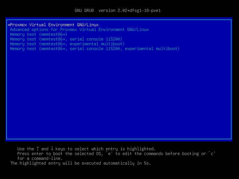
The simplest and most reliable way to determine which bootloader is used, is to watch the boot process of the Proxmox VE node.
You will either see the blue box of GRUB or the simple black on white systemd-boot.
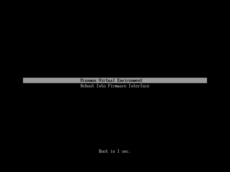
Determining the bootloader from a running system might not be 100% accurate. The safest way is to run the following command:
# efibootmgr -v
If it returns a message that EFI variables are not supported, GRUB is used in BIOS/Legacy mode.
If the output contains a line that looks similar to the following, GRUB is used in UEFI mode.
Boot0005* proxmox [...] File(\EFI\proxmox\grubx64.efi)
If the output contains a line similar to the following, systemd-boot is used.
Boot0006* Linux Boot Manager [...] File(\EFI\systemd\systemd-bootx64.efi)
By running:
# proxmox-boot-tool status
you can find out if proxmox-boot-tool is configured, which is a good indication of how the system is booted.
3.13.4. GRUB
GRUB has been the de-facto standard for booting Linux systems for many years
and is quite well documented
[GRUB Manual https://www.gnu.org/software/grub/manual/grub/grub.html]
.
Configuration
Changes to the GRUB configuration are done via the defaults file
/etc/default/grub or config snippets in /etc/default/grub.d. To regenerate
the configuration file after a change to the configuration run:
[Systems using proxmox-boot-tool will call proxmox-boot-tool
refresh upon update-grub.]
# update-grub
3.13.5. Systemd-boot
systemd-boot is a lightweight EFI bootloader. It reads the kernel and initrd images directly from the EFI Service Partition (ESP) where it is installed. The main advantage of directly loading the kernel from the ESP is that it does not need to reimplement the drivers for accessing the storage. In Proxmox VE proxmox-boot-tool is used to keep the configuration on the ESPs synchronized.
Configuration
systemd-boot is configured via the file loader/loader.conf in the root directory of an EFI System Partition (ESP). See the loader.conf(5) manpage for details.
Each bootloader entry is placed in a file of its own in the directory loader/entries/
An example entry.conf looks like this (/ refers to the root of the ESP):
title    Proxmox
version  5.0.15-1-pve
options   root=ZFS=rpool/ROOT/pve-1 boot=zfs
linux    /EFI/proxmox/5.0.15-1-pve/vmlinuz-5.0.15-1-pve
initrd   /EFI/proxmox/5.0.15-1-pve/initrd.img-5.0.15-1-pve
3.13.6. Editing the Kernel Commandline
You can modify the kernel commandline in the following places, depending on the bootloader used:
The kernel commandline needs to be placed in the variable GRUB_CMDLINE_LINUX_DEFAULT in the file /etc/default/grub. Running update-grub appends its content to all linux entries in /boot/grub/grub.cfg.
The kernel commandline needs to be placed as one line in /etc/kernel/cmdline. To apply your changes, run proxmox-boot-tool refresh, which sets it as the option line for all config files in loader/entries/proxmox-*.conf.
A complete list of kernel parameters can be found at https://www.kernel.org/doc/html/v<YOUR-KERNEL-VERSION>/admin-guide/kernel-parameters.html. replace <YOUR-KERNEL-VERSION> with the major.minor version, for example, for kernels based on version 6.5 the URL would be: https://www.kernel.org/doc/html/v6.5/admin-guide/kernel-parameters.html
You can find your kernel version by checking the web interface (Node → Summary), or by running
# uname -r
Use the first two numbers at the front of the output.
3.13.7. Override the Kernel-Version for next Boot
To select a kernel that is not currently the default kernel, you can either:
-
use the boot loader menu that is displayed at the beginning of the boot process
-
use the proxmox-boot-tool to pin the system to a kernel version either once or permanently (until pin is reset).
This should help you work around incompatibilities between a newer kernel version and the hardware.
|
|
Such a pin should be removed as soon as possible so that all current security patches of the latest kernel are also applied to the system. |
For example: To permanently select the version 5.15.30-1-pve for booting you would run:
# proxmox-boot-tool kernel pin 5.15.30-1-pve
|
|
The pinning functionality works for all Proxmox VE systems, not only those using proxmox-boot-tool to synchronize the contents of the ESPs, if your system does not use proxmox-boot-tool for synchronizing you can also skip the proxmox-boot-tool refresh call in the end. |
You can also set a kernel version to be booted on the next system boot only. This is for example useful to test if an updated kernel has resolved an issue, which caused you to pin a version in the first place:
# proxmox-boot-tool kernel pin 5.15.30-1-pve --next-boot
To remove any pinned version configuration use the unpin subcommand:
# proxmox-boot-tool kernel unpin
While unpin has a --next-boot option as well, it is used to clear a pinned version set with --next-boot. As that happens already automatically on boot, invonking it manually is of little use.
After setting, or clearing pinned versions you also need to synchronize the content and configuration on the ESPs by running the refresh subcommand.
|
|
You will be prompted to automatically do for proxmox-boot-tool managed systems if you call the tool interactively. |
# proxmox-boot-tool refresh
3.13.8. Secure Boot
Since Proxmox VE 8.1, Secure Boot is supported out of the box via signed packages and integration in proxmox-boot-tool.
The following packages are required for secure boot to work. You can install them all at once by using the ‘proxmox-secure-boot-support’ meta-package.
-
shim-signed (shim bootloader signed by Microsoft)
-
shim-helpers-amd64-signed (fallback bootloader and MOKManager, signed by Proxmox)
-
grub-efi-amd64-signed (GRUB EFI bootloader, signed by Proxmox)
-
proxmox-kernel-6.X.Y-Z-pve-signed (Kernel image, signed by Proxmox)
Only GRUB is supported as bootloader out of the box, since other bootloader are currently not eligible for secure boot code-signing.
Any new installation of Proxmox VE will automatically have all of the above packages included.
More details about how Secure Boot works, and how to customize the setup, are available in our wiki.
Switching an Existing Installation to Secure Boot
|
|
This can lead to an unbootable installation in some cases if not done correctly. Reinstalling the host will setup Secure Boot automatically if available, without any extra interactions. Make sure you have a working and well-tested backup of your Proxmox VE host! |
An existing UEFI installation can be switched over to Secure Boot if desired, without having to reinstall Proxmox VE from scratch.
First, ensure all your system is up-to-date. Next, install proxmox-secure-boot-support. GRUB automatically creates the needed EFI boot entry for booting via the default shim.
If systemd-boot is used as a bootloader (see Determine which Bootloader is used), some additional setup is needed. This is only the case if Proxmox VE was installed with ZFS-on-root.
To check the latter, run:
# findmnt /
If the host is indeed using ZFS as root filesystem, the FSTYPE column should contain zfs:
TARGET SOURCE           FSTYPE OPTIONS
/      rpool/ROOT/pve-1 zfs    rw,relatime,xattr,noacl,casesensitive
Next, a suitable potential ESP (EFI system partition) must be found. This can be done using the lsblk command as following:
# lsblk -o +FSTYPE
The output should look something like this:
NAME   MAJ:MIN RM  SIZE RO TYPE MOUNTPOINTS FSTYPE
sda      8:0    0   32G  0 disk
├─sda1   8:1    0 1007K  0 part
├─sda2   8:2    0  512M  0 part             vfat
└─sda3   8:3    0 31.5G  0 part             zfs_member
sdb      8:16   0   32G  0 disk
├─sdb1   8:17   0 1007K  0 part
├─sdb2   8:18   0  512M  0 part             vfat
└─sdb3   8:19   0 31.5G  0 part             zfs_member
In this case, the partitions sda2 and sdb2 are the targets. They can be identified by the their size of 512M and their FSTYPE being vfat, in this case on a ZFS RAID-1 installation.
These partitions must be properly set up for booting through GRUB using proxmox-boot-tool. This command (using sda2 as an example) must be run separately for each individual ESP:
# proxmox-boot-tool init /dev/sda2 grub
Afterwards, you can sanity-check the setup by running the following command:
# efibootmgr -v
This list should contain an entry looking similar to this:
[..]
Boot0009* proxmox       HD(2,GPT,..,0x800,0x100000)/File(\EFI\proxmox\shimx64.efi)
[..]
|
|
The old systemd-boot bootloader will be kept, but GRUB will be preferred. This way, if booting using GRUB in Secure Boot mode does not work for any reason, the system can still be booted using systemd-boot with Secure Boot turned off. |
Now the host can be rebooted and Secure Boot enabled in the UEFI firmware setup utility.
On reboot, a new entry named proxmox should be selectable in the UEFI firmware boot menu, which boots using the pre-signed EFI shim.
If, for any reason, no proxmox entry can be found in the UEFI boot menu, you can try adding it manually (if supported by the firmware), by adding the file \EFI\proxmox\shimx64.efi as a custom boot entry.
|
|
Some UEFI firmwares are known to drop the proxmox boot option on reboot. This can happen if the proxmox boot entry is pointing to a GRUB installation on a disk, where the disk itself is not a boot option. If possible, try adding the disk as a boot option in the UEFI firmware setup utility and run proxmox-boot-tool again. |
|
|
To enroll custom keys, see the accompanying Secure Boot wiki page. |
Using DKMS/Third Party Modules With Secure Boot
On systems with Secure Boot enabled, the kernel will refuse to load modules which are not signed by a trusted key. The default set of modules shipped with the kernel packages is signed with an ephemeral key embedded in the kernel image which is trusted by that specific version of the kernel image.
In order to load other modules, such as those built with DKMS or manually, they need to be signed with a key trusted by the Secure Boot stack. The easiest way to achieve this is to enroll them as Machine Owner Key (MOK) with mokutil.
The dkms tool will automatically generate a keypair and certificate in /var/lib/dkms/mok.key and /var/lib/dkms/mok.pub and use it for signing the kernel modules it builds and installs.
You can view the certificate contents with
# openssl x509 -in /var/lib/dkms/mok.pub -noout -text
and enroll it on your system using the following command:
# mokutil --import /var/lib/dkms/mok.pub
input password:
input password again:
The mokutil command will ask for a (temporary) password twice, this password needs to be entered one more time in the next step of the process! Rebooting the system should automatically boot into the MOKManager EFI binary, which allows you to verify the key/certificate and confirm the enrollment using the password selected when starting the enrollment using mokutil. Afterwards, the kernel should allow loading modules built with DKMS (which are signed with the enrolled MOK). The MOK can also be used to sign custom EFI binaries and kernel images if desired.
The same procedure can also be used for custom/third-party modules not managed with DKMS, but the key/certificate generation and signing steps need to be done manually in that case.
3.14. Kernel Samepage Merging (KSM)
Kernel Samepage Merging (KSM) is an optional memory deduplication feature offered by the Linux kernel, which is enabled by default in Proxmox VE. KSM works by scanning a range of physical memory pages for identical content, and identifying the virtual pages that are mapped to them. If identical pages are found, the corresponding virtual pages are re-mapped so that they all point to the same physical page, and the old pages are freed. The virtual pages are marked as "copy-on-write", so that any writes to them will be written to a new area of memory, leaving the shared physical page intact.
3.14.1. Implications of KSM
KSM can optimize memory usage in virtualization environments, as multiple VMs running similar operating systems or workloads could potentially share a lot of common memory pages.
However, while KSM can reduce memory usage, it also comes with some security risks, as it can expose VMs to side-channel attacks. Research has shown that it is possible to infer information about a running VM via a second VM on the same host, by exploiting certain characteristics of KSM.
Thus, if you are using Proxmox VE to provide hosting services, you should consider disabling KSM, in order to provide your users with additional security. Furthermore, you should check your country’s regulations, as disabling KSM may be a legal requirement.
3.14.2. Disabling KSM
To see if KSM is active, you can check the output of:
# systemctl status ksmtuned
If it is, it can be disabled immediately with:
# systemctl disable --now ksmtuned
Finally, to unmerge all the currently merged pages, run:
# echo 2 > /sys/kernel/mm/ksm/run
4. Graphical User Interface
Proxmox VE is simple. There is no need to install a separate management tool, and everything can be done through your web browser (Latest Firefox or Google Chrome is preferred). A built-in HTML5 console is used to access the guest console. As an alternative, SPICE can be used.
Because we use the Proxmox cluster file system (pmxcfs), you can connect to any node to manage the entire cluster. Each node can manage the entire cluster. There is no need for a dedicated manager node.
You can use the web-based administration interface with any modern browser. When Proxmox VE detects that you are connecting from a mobile device, you are redirected to a simpler, touch-based user interface.
The web interface can be reached via https://youripaddress:8006 (default login is: root, and the password is specified during the installation process).
4.1. Features
-
Seamless integration and management of Proxmox VE clusters
-
AJAX technologies for dynamic updates of resources
-
Secure access to all Virtual Machines and Containers via SSL encryption (https)
-
Fast search-driven interface, capable of handling hundreds and probably thousands of VMs
-
Secure HTML5 console or SPICE
-
Role based permission management for all objects (VMs, storages, nodes, etc.)
-
Support for multiple authentication sources (e.g. local, MS ADS, LDAP, …)
-
Two-Factor Authentication (OATH, Yubikey)
-
Based on ExtJS 7.x JavaScript framework
4.2. Login
When you connect to the server, you will first see the login window. Proxmox VE supports various authentication backends (Realm), and you can select the language here. The GUI is translated to more than 20 languages.
|
|
You can save the user name on the client side by selecting the checkbox at the bottom. This saves some typing when you login next time. |
4.3. GUI Overview
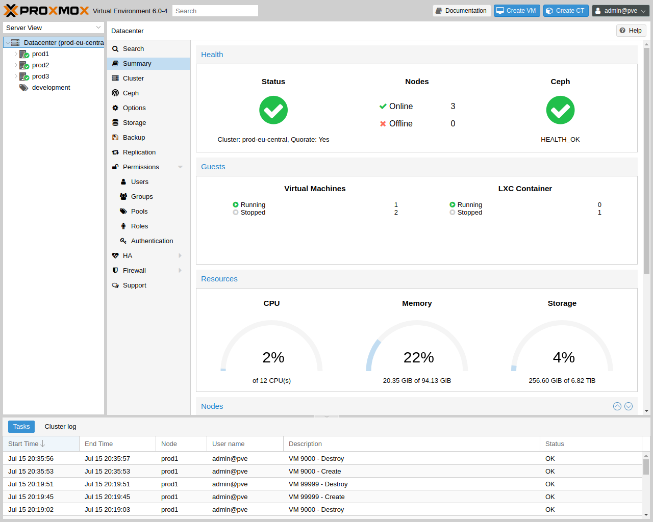
The Proxmox VE user interface consists of four regions.
|
Header
|
On top. Shows status information and contains buttons for most important actions. |
|
Resource Tree
|
At the left side. A navigation tree where you can select specific objects. |
|
Content Panel
|
Center region. Selected objects display configuration options and status here. |
|
Log Panel
|
At the bottom. Displays log entries for recent tasks. You can double-click on those log entries to get more details, or to abort a running task. |
|
|
You can shrink and expand the size of the resource tree and log panel, or completely hide the log panel. This can be helpful when you work on small displays and want more space to view other content. |
4.3.1. Header
On the top left side, the first thing you see is the Proxmox logo. Next to it is the current running version of Proxmox VE. In the search bar nearside you can search for specific objects (VMs, containers, nodes, …). This is sometimes faster than selecting an object in the resource tree.
The right part of the header contains four buttons:
|
Documentation
|
Opens a new browser window showing the reference documentation. |
|
Create VM
|
Opens the virtual machine creation wizard. |
|
Create CT
|
Open the container creation wizard. |
|
User Menu
|
Displays the identity of the user you’re currently logged in with, and clicking it opens a menu with user-specific options. In the user menu, you’ll find the My Settings dialog, which provides local UI settings. Below that, there are shortcuts for TFA (Two-Factor Authentication) and Password self-service. You’ll also find options to change the Language and the Color Theme. Finally, at the bottom of the menu is the Logout option. |
4.3.2. My Settings
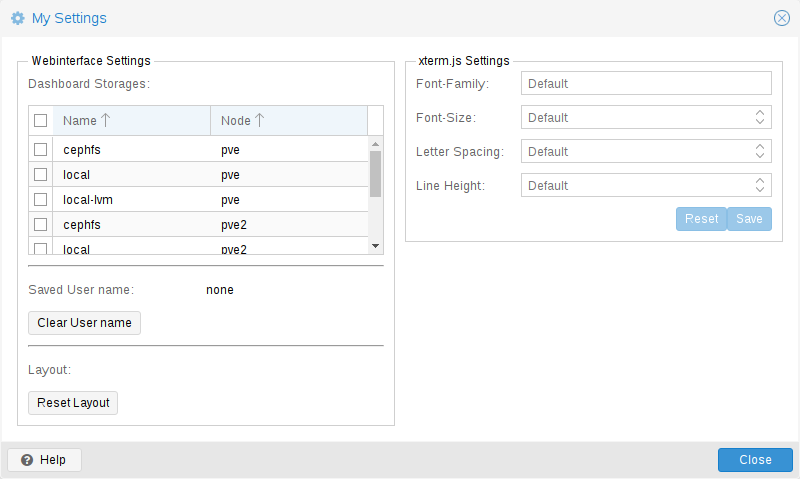
The My Settings window allows you to set locally stored settings. These include the Dashboard Storages which allow you to enable or disable specific storages to be counted towards the total amount visible in the datacenter summary. If no storage is checked the total is the sum of all storages, same as enabling every single one.
Below the dashboard settings you find the stored user name and a button to clear it as well as a button to reset every layout in the GUI to its default.
On the right side there are xterm.js Settings. These contain the following options:
|
Font-Family
|
The font to be used in xterm.js (e.g. Arial). |
|
Font-Size
|
The preferred font size to be used. |
|
Letter Spacing
|
Increases or decreases spacing between letters in text. |
|
Line Height
|
Specify the absolute height of a line. |
4.3.3. Resource Tree
This is the main navigation tree. On top of the tree you can select some predefined views, which change the structure of the tree below. The default view is the Server View, and it shows the following object types:
|
Datacenter
|
Contains cluster-wide settings (relevant for all nodes). |
|
Node
|
Represents the hosts inside a cluster, where the guests run. |
|
Guest
|
VMs, containers and templates. |
|
Storage
|
Data Storage. |
|
Pool
|
It is possible to group guests using a pool to simplify management. |
The following view types are available:
|
Server View
|
Shows all kinds of objects, grouped by nodes. |
|
Folder View
|
Shows all kinds of objects, grouped by object type. |
|
Pool View
|
Show VMs and containers, grouped by pool. |
4.3.4. Log Panel
The main purpose of the log panel is to show you what is currently going on in your cluster. Actions like creating an new VM are executed in the background, and we call such a background job a task.
Any output from such a task is saved into a separate log file. You can view that log by simply double-click a task log entry. It is also possible to abort a running task there.
Please note that we display the most recent tasks from all cluster nodes here. So you can see when somebody else is working on another cluster node in real-time.
|
|
We remove older and finished task from the log panel to keep that list short. But you can still find those tasks within the node panel in the Task History. |
Some short-running actions simply send logs to all cluster members. You can see those messages in the Cluster log panel.
4.4. Content Panels
When you select an item from the resource tree, the corresponding object displays configuration and status information in the content panel. The following sections provide a brief overview of this functionality. Please refer to the corresponding chapters in the reference documentation to get more detailed information.
4.4.1. Datacenter
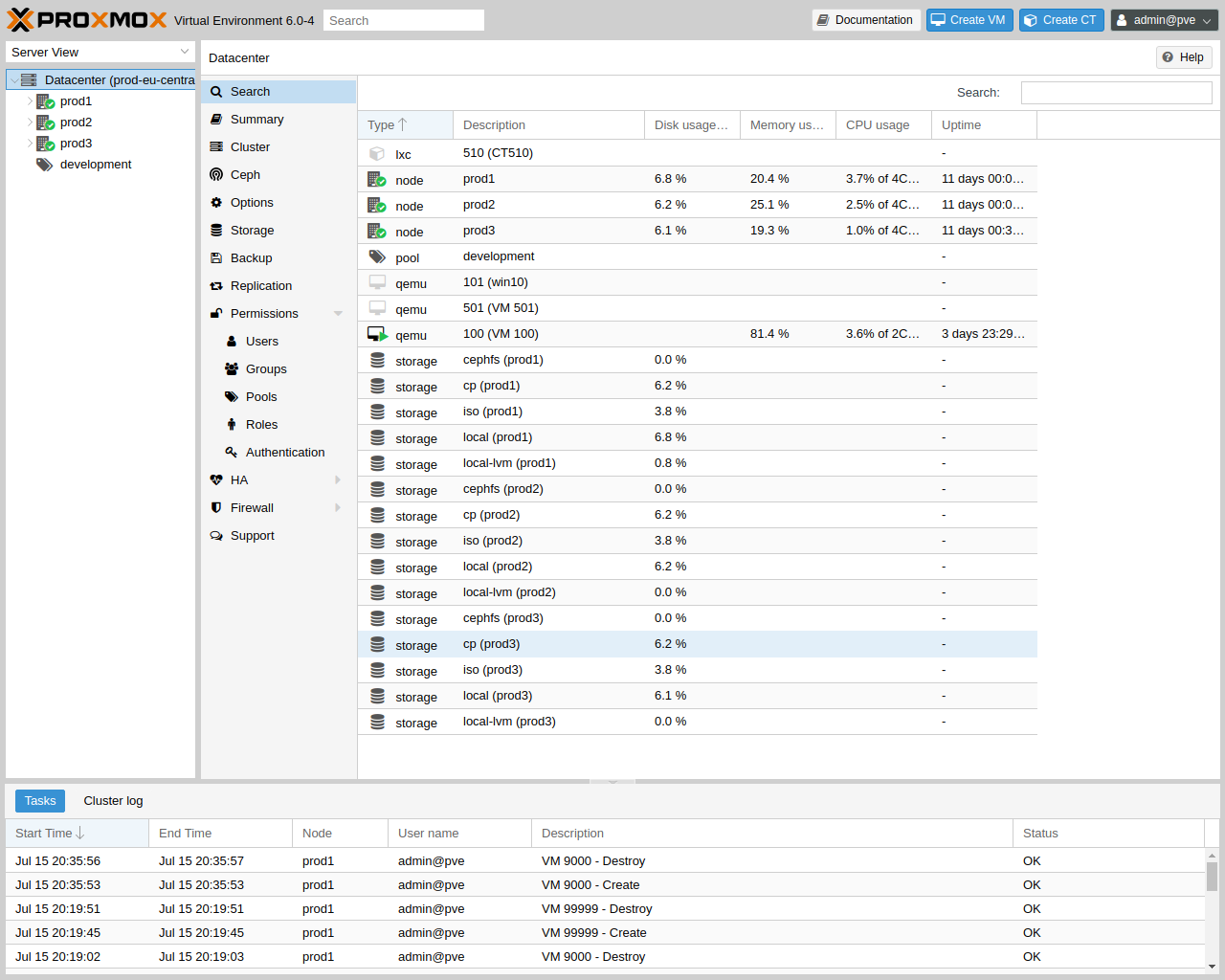
On the datacenter level, you can access cluster-wide settings and information.
-
Search: perform a cluster-wide search for nodes, VMs, containers, storage devices, and pools.
-
Summary: gives a brief overview of the cluster’s health and resource usage.
-
Cluster: provides the functionality and information necessary to create or join a cluster.
-
Options: view and manage cluster-wide default settings.
-
Storage: provides an interface for managing cluster storage.
-
Backup: schedule backup jobs. This operates cluster wide, so it doesn’t matter where the VMs/containers are on your cluster when scheduling.
-
Replication: view and manage replication jobs.
-
Permissions: manage user, group, and API token permissions, and LDAP, MS-AD and Two-Factor authentication.
-
HA: manage Proxmox VE High Availability.
-
ACME: set up ACME (Let’s Encrypt) certificates for server nodes.
-
Firewall: configure and make templates for the Proxmox Firewall cluster wide.
-
Metric Server: define external metric servers for Proxmox VE.
-
Notifications: configurate notification behavior and targets for Proxmox VE.
-
Support: display information about your support subscription.
4.4.2. Nodes
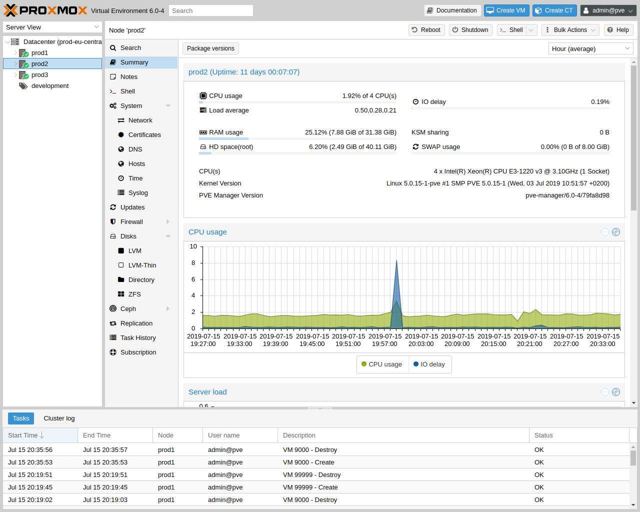
Nodes in your cluster can be managed individually at this level.
The top header has useful buttons such as Reboot, Shutdown, Shell, Bulk Actions and Help. Shell has the options noVNC, SPICE and xterm.js. Bulk Actions has the options Bulk Start, Bulk Shutdown and Bulk Migrate.
-
Search: search a node for VMs, containers, storage devices, and pools.
-
Summary: display a brief overview of the node’s resource usage.
-
Notes: write custom comments in Markdown syntax.
-
Shell: access to a shell interface for the node.
-
System: configure network, DNS and time settings, and access the syslog.
-
Updates: upgrade the system and see the available new packages.
-
Firewall: manage the Proxmox Firewall for a specific node.
-
Disks: get an overview of the attached disks, and manage how they are used.
-
Ceph: is only used if you have installed a Ceph server on your host. In this case, you can manage your Ceph cluster and see the status of it here.
-
Replication: view and manage replication jobs.
-
Task History: see a list of past tasks.
-
Subscription: upload a subscription key, and generate a system report for use in support cases.
4.4.3. Guests
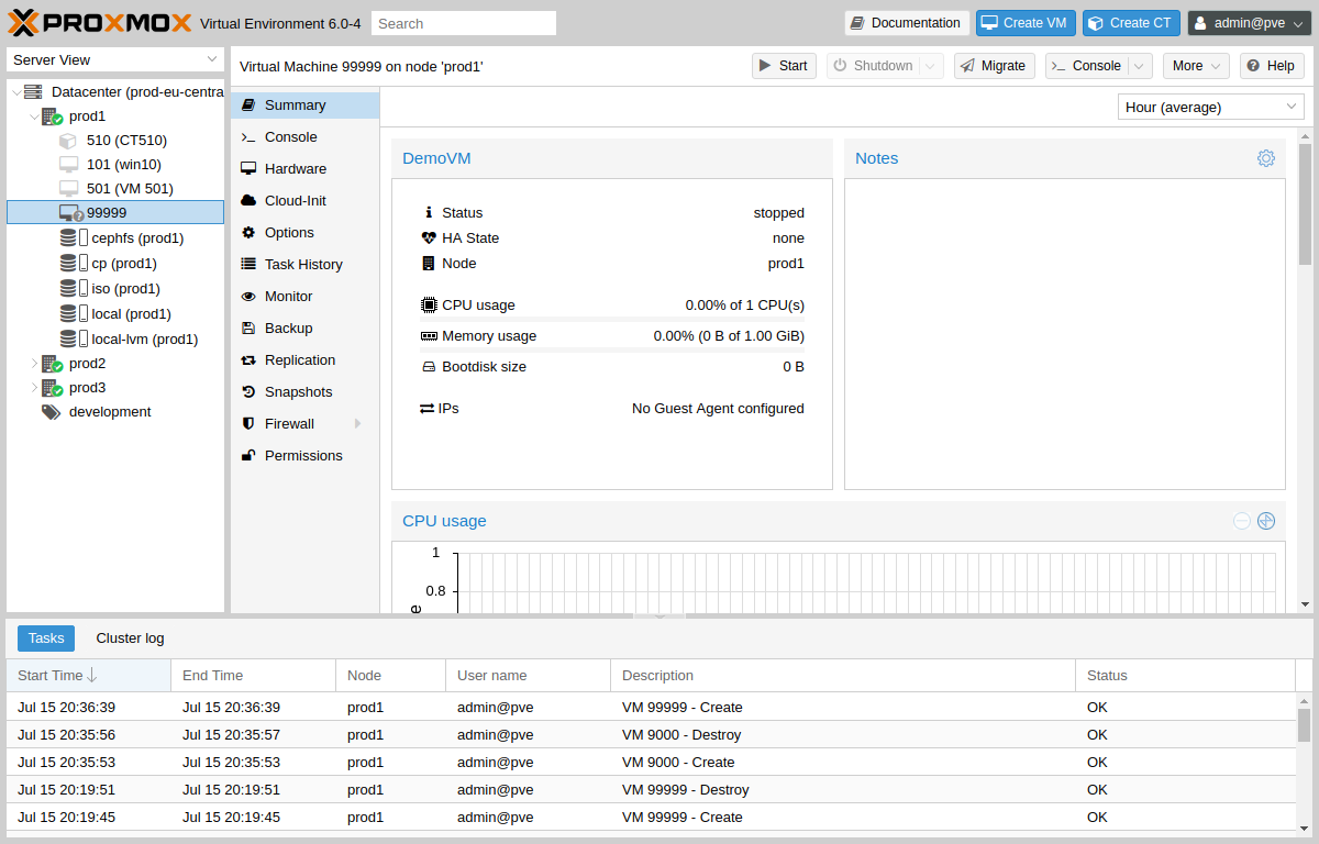
There are two different kinds of guests and both can be converted to a template. One of them is a Kernel-based Virtual Machine (KVM) and the other is a Linux Container (LXC). Navigation for these are mostly the same; only some options are different.
To access the various guest management interfaces, select a VM or container from the menu on the left.
The header contains commands for items such as power management, migration, console access and type, cloning, HA, and help. Some of these buttons contain drop-down menus, for example, Shutdown also contains other power options, and Console contains the different console types: SPICE, noVNC and xterm.js.
The panel on the right contains an interface for whatever item is selected from the menu on the left.
The available interfaces are as follows.
-
Summary: provides a brief overview of the VM’s activity and a Notes field for Markdown syntax comments.
-
Console: access to an interactive console for the VM/container.
-
(KVM)Hardware: define the hardware available to the KVM VM.
-
(LXC)Resources: define the system resources available to the LXC.
-
(LXC)Network: configure a container’s network settings.
-
(LXC)DNS: configure a container’s DNS settings.
-
Options: manage guest options.
-
Task History: view all previous tasks related to the selected guest.
-
(KVM) Monitor: an interactive communication interface to the KVM process.
-
Backup: create and restore system backups.
-
Replication: view and manage the replication jobs for the selected guest.
-
Snapshots: create and restore VM snapshots.
-
Firewall: configure the firewall on the VM level.
-
Permissions: manage permissions for the selected guest.
4.4.4. Storage
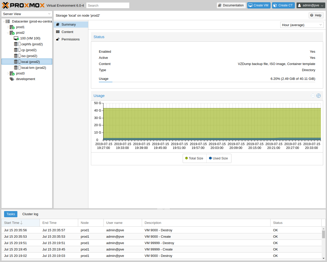
As with the guest interface, the interface for storage consists of a menu on the left for certain storage elements and an interface on the right to manage these elements.
In this view we have a two partition split-view. On the left side we have the storage options and on the right side the content of the selected option will be shown.
-
Summary: shows important information about the storage, such as the type, usage, and content which it stores.
-
Content: a menu item for each content type which the storage stores, for example, Backups, ISO Images, CT Templates.
-
Permissions: manage permissions for the storage.
4.4.5. Pools
Again, the pools view comprises two partitions: a menu on the left, and the corresponding interfaces for each menu item on the right.
-
Summary: shows a description of the pool.
-
Members: display and manage pool members (guests and storage).
-
Permissions: manage the permissions for the pool.
4.5. Tags
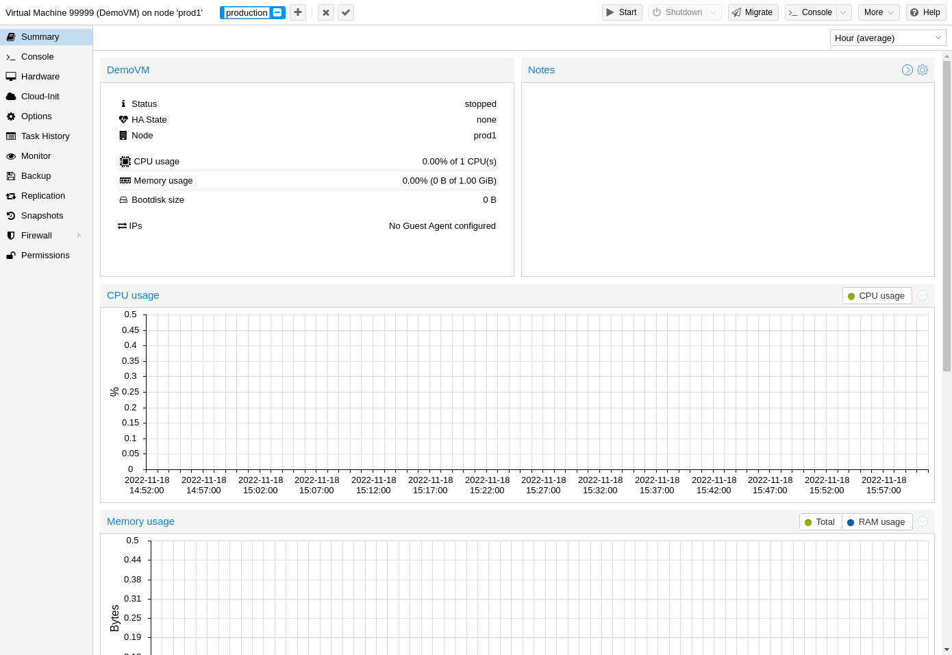
For organizational purposes, it is possible to set tags for guests. Currently, these only provide informational value to users. Tags are displayed in two places in the web interface: in the Resource Tree and in the status line when a guest is selected.
Tags can be added, edited, and removed in the status line of the guest by clicking on the pencil icon. You can add multiple tags by pressing the + button and remove them by pressing the - button. To save or cancel the changes, you can use the ✓ and x button respectively.
Tags can also be set via the CLI, where multiple tags are separated by semicolons. For example:
# qm set ID --tags myfirsttag;mysecondtag
4.5.1. Style Configuration
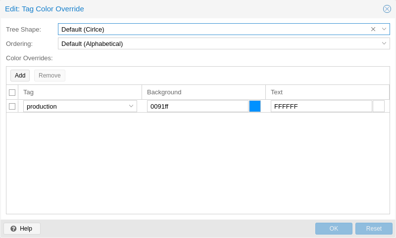
By default, the tag colors are derived from their text in a deterministic way. The color, shape in the resource tree, and case-sensitivity, as well as how tags are sorted, can be customized. This can be done via the web interface under Datacenter → Options → Tag Style Override. Alternatively, this can be done via the CLI. For example:
# pvesh set /cluster/options --tag-style color-map=example:000000:FFFFFF
sets the background color of the tag example to black (#000000) and the text color to white (#FFFFFF).
4.5.2. Permissions
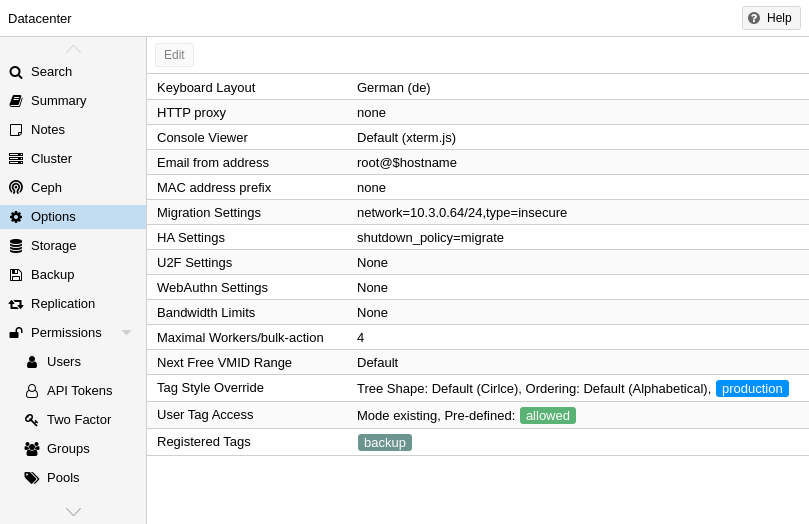
By default, users with the privilege VM.Config.Options on a guest (/vms/ID) can set any tags they want (see Permission Management). If you want to restrict this behavior, appropriate permissions can be set under Datacenter → Options → User Tag Access:
-
free: users are not restricted in setting tags (Default)
-
list: users can set tags based on a predefined list of tags
-
existing: like list but users can also use already existing tags
-
none: users are restricted from using tags
The same can also be done via the CLI.
Note that a user with the Sys.Modify privileges on / is always able to set or delete any tags, regardless of the settings here. Additionally, there is a configurable list of registered tags which can only be added and removed by users with the privilege Sys.Modify on /. The list of registered tags can be edited under Datacenter → Options → Registered Tags or via the CLI.
For more details on the exact options and how to invoke them in the CLI, see Datacenter Configuration.
5. Cluster Manager
The Proxmox VE cluster manager pvecm is a tool to create a group of physical servers. Such a group is called a cluster. We use the Corosync Cluster Engine for reliable group communication. There’s no explicit limit for the number of nodes in a cluster. In practice, the actual possible node count may be limited by the host and network performance. Currently (2021), there are reports of clusters (using high-end enterprise hardware) with over 50 nodes in production.
pvecm can be used to create a new cluster, join nodes to a cluster, leave the cluster, get status information, and do various other cluster-related tasks. The Proxmox Cluster File System (“pmxcfs”) is used to transparently distribute the cluster configuration to all cluster nodes.
Grouping nodes into a cluster has the following advantages:
-
Centralized, web-based management
-
Multi-master clusters: each node can do all management tasks
-
Use of pmxcfs, a database-driven file system, for storing configuration files, replicated in real-time on all nodes using corosync
-
Easy migration of virtual machines and containers between physical hosts
-
Fast deployment
-
Cluster-wide services like firewall and HA
5.1. Requirements
-
All nodes must be able to connect to each other via UDP ports 5405-5412 for corosync to work.
-
Date and time must be synchronized.
-
An SSH tunnel on TCP port 22 between nodes is required.
-
If you are interested in High Availability, you need to have at least three nodes for reliable quorum. All nodes should have the same version.
-
We recommend a dedicated NIC for the cluster traffic, especially if you use shared storage.
-
The root password of a cluster node is required for adding nodes.
-
Online migration of virtual machines is only supported when nodes have CPUs from the same vendor. It might work otherwise, but this is never guaranteed.
|
|
It is not possible to mix Proxmox VE 3.x and earlier with Proxmox VE 4.X cluster nodes. |
|
|
While it’s possible to mix Proxmox VE 4.4 and Proxmox VE 5.0 nodes, doing so is not supported as a production configuration and should only be done temporarily, during an upgrade of the whole cluster from one major version to another. |
|
|
Running a cluster of Proxmox VE 6.x with earlier versions is not possible. The cluster protocol (corosync) between Proxmox VE 6.x and earlier versions changed fundamentally. The corosync 3 packages for Proxmox VE 5.4 are only intended for the upgrade procedure to Proxmox VE 6.0. |
5.2. Preparing Nodes
First, install Proxmox VE on all nodes. Make sure that each node is installed with the final hostname and IP configuration. Changing the hostname and IP is not possible after cluster creation.
While it’s common to reference all node names and their IPs in /etc/hosts (or make their names resolvable through other means), this is not necessary for a cluster to work. It may be useful however, as you can then connect from one node to another via SSH, using the easier to remember node name (see also Link Address Types). Note that we always recommend referencing nodes by their IP addresses in the cluster configuration.
5.3. Create a Cluster
You can either create a cluster on the console (login via ssh), or through the API using the Proxmox VE web interface (Datacenter → Cluster).
|
|
Use a unique name for your cluster. This name cannot be changed later. The cluster name follows the same rules as node names. |
5.3.1. Create via Web GUI
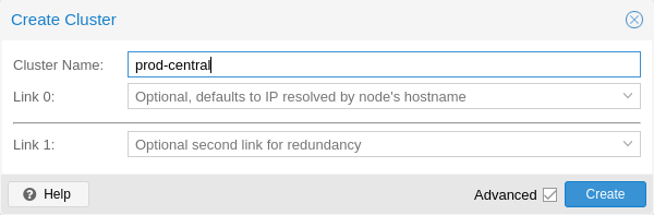
Under Datacenter → Cluster, click on Create Cluster. Enter the cluster name and select a network connection from the drop-down list to serve as the main cluster network (Link 0). It defaults to the IP resolved via the node’s hostname.
As of Proxmox VE 6.2, up to 8 fallback links can be added to a cluster. To add a redundant link, click the Add button and select a link number and IP address from the respective fields. Prior to Proxmox VE 6.2, to add a second link as fallback, you can select the Advanced checkbox and choose an additional network interface (Link 1, see also Corosync Redundancy).
|
|
Ensure that the network selected for cluster communication is not used for any high traffic purposes, like network storage or live-migration. While the cluster network itself produces small amounts of data, it is very sensitive to latency. Check out full cluster network requirements. |
5.3.2. Create via the Command Line
Login via ssh to the first Proxmox VE node and run the following command:
hp1# pvecm create CLUSTERNAME
To check the state of the new cluster use:
hp1# pvecm status
5.3.3. Multiple Clusters in the Same Network
It is possible to create multiple clusters in the same physical or logical network. In this case, each cluster must have a unique name to avoid possible clashes in the cluster communication stack. Furthermore, this helps avoid human confusion by making clusters clearly distinguishable.
While the bandwidth requirement of a corosync cluster is relatively low, the latency of packages and the package per second (PPS) rate is the limiting factor. Different clusters in the same network can compete with each other for these resources, so it may still make sense to use separate physical network infrastructure for bigger clusters.
5.4. Adding Nodes to the Cluster
|
|
All existing configuration in /etc/pve is overwritten when joining a cluster. In particular, a joining node cannot hold any guests, since guest IDs could otherwise conflict, and the node will inherit the cluster’s storage configuration. To join a node with existing guest, as a workaround, you can create a backup of each guest (using vzdump) and restore it under a different ID after joining. If the node’s storage layout differs, you will need to re-add the node’s storages, and adapt each storage’s node restriction to reflect on which nodes the storage is actually available. |
5.4.1. Join Node to Cluster via GUI
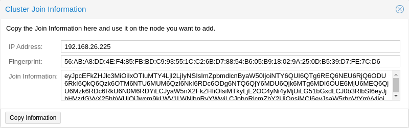
Log in to the web interface on an existing cluster node. Under Datacenter → Cluster, click the Join Information button at the top. Then, click on the button Copy Information. Alternatively, copy the string from the Information field manually.
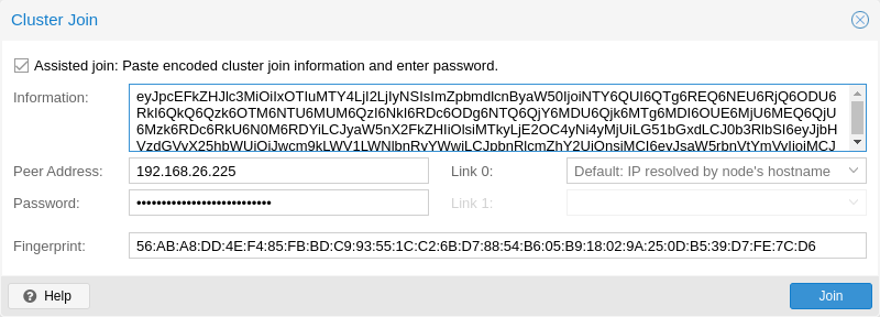
Next, log in to the web interface on the node you want to add. Under Datacenter → Cluster, click on Join Cluster. Fill in the Information field with the Join Information text you copied earlier. Most settings required for joining the cluster will be filled out automatically. For security reasons, the cluster password has to be entered manually.
|
|
To enter all required data manually, you can disable the Assisted Join checkbox. |
After clicking the Join button, the cluster join process will start immediately. After the node has joined the cluster, its current node certificate will be replaced by one signed from the cluster certificate authority (CA). This means that the current session will stop working after a few seconds. You then might need to force-reload the web interface and log in again with the cluster credentials.
Now your node should be visible under Datacenter → Cluster.
5.4.2. Join Node to Cluster via Command Line
Log in to the node you want to join into an existing cluster via ssh.
# pvecm add IP-ADDRESS-CLUSTER
For IP-ADDRESS-CLUSTER, use the IP or hostname of an existing cluster node. An IP address is recommended (see Link Address Types).
To check the state of the cluster use:
# pvecm status
 # pvecm status
Cluster information
~~~~~~~~~~~~~~~~~~~
Name:             prod-central
Config Version:   3
Transport:        knet
Secure auth:      on

Quorum information
~~~~~~~~~~~~~~~~~~
Date:             Tue Sep 14 11:06:47 2021
Quorum provider:  corosync_votequorum
Nodes:            4
Node ID:          0x00000001
Ring ID:          1.1a8
Quorate:          Yes

Votequorum information
~~~~~~~~~~~~~~~~~~~~~~
Expected votes:   4
Highest expected: 4
Total votes:      4
Quorum:           3
Flags:            Quorate

Membership information
~~~~~~~~~~~~~~~~~~~~~~
    Nodeid      Votes Name
0x00000001          1 192.168.15.91
0x00000002          1 192.168.15.92 (local)
0x00000003          1 192.168.15.93
0x00000004          1 192.168.15.94
If you only want a list of all nodes, use:
# pvecm nodes
 # pvecm nodes

Membership information
~~~~~~~~~~~~~~~~~~~~~~
    Nodeid      Votes Name
         1          1 hp1
         2          1 hp2 (local)
         3          1 hp3
         4          1 hp4
5.4.3. Adding Nodes with Separated Cluster Network
When adding a node to a cluster with a separated cluster network, you need to use the link0 parameter to set the nodes address on that network:
# pvecm add IP-ADDRESS-CLUSTER --link0 LOCAL-IP-ADDRESS-LINK0If you want to use the built-in redundancy of the Kronosnet transport layer, also use the link1 parameter.
Using the GUI, you can select the correct interface from the corresponding Link X fields in the Cluster Join dialog.
5.5. Remove a Cluster Node
|
|
Read the procedure carefully before proceeding, as it may not be what you want or need. |
Move all virtual machines from the node. Ensure that you have made copies of any local data or backups that you want to keep. In addition, make sure to remove any scheduled replication jobs to the node to be removed.
|
|
Failure to remove replication jobs to a node before removing said node will result in the replication job becoming irremovable. Especially note that replication automatically switches direction if a replicated VM is migrated, so by migrating a replicated VM from a node to be deleted, replication jobs will be set up to that node automatically. |
In the following example, we will remove the node hp4 from the cluster.
Log in to a different cluster node (not hp4), and issue a pvecm nodes command to identify the node ID to remove:
 hp1# pvecm nodes

Membership information
~~~~~~~~~~~~~~~~~~~~~~
    Nodeid      Votes Name
         1          1 hp1 (local)
         2          1 hp2
         3          1 hp3
         4          1 hp4
At this point, you must power off hp4 and ensure that it will not power on again (in the network) with its current configuration.
|
|
As mentioned above, it is critical to power off the node before removal, and make sure that it will not power on again (in the existing cluster network) with its current configuration. If you power on the node as it is, the cluster could end up broken, and it could be difficult to restore it to a functioning state. |
After powering off the node hp4, we can safely remove it from the cluster.
 hp1# pvecm delnode hp4
 Killing node 4
|
|
At this point, it is possible that you will receive an error message stating Could not kill node (error = CS_ERR_NOT_EXIST). This does not signify an actual failure in the deletion of the node, but rather a failure in corosync trying to kill an offline node. Thus, it can be safely ignored. |
Use pvecm nodes or pvecm status to check the node list again. It should look something like:
hp1# pvecm status

...

Votequorum information
~~~~~~~~~~~~~~~~~~~~~~
Expected votes:   3
Highest expected: 3
Total votes:      3
Quorum:           2
Flags:            Quorate

Membership information
~~~~~~~~~~~~~~~~~~~~~~
    Nodeid      Votes Name
0x00000001          1 192.168.15.90 (local)
0x00000002          1 192.168.15.91
0x00000003          1 192.168.15.92
If, for whatever reason, you want this server to join the same cluster again, you have to:
-
do a fresh install of Proxmox VE on it,
-
then join it, as explained in the previous section.
The configuration files for the removed node will still reside in /etc/pve/nodes/hp4. Recover any configuration you still need and remove the directory afterwards.
|
|
After removal of the node, its SSH fingerprint will still reside in the known_hosts of the other nodes. If you receive an SSH error after rejoining a node with the same IP or hostname, run pvecm updatecerts once on the re-added node to update its fingerprint cluster wide. |
5.5.1. Separate a Node Without Reinstalling
|
|
This is not the recommended method, proceed with caution. Use the previous method if you’re unsure. |
You can also separate a node from a cluster without reinstalling it from scratch. But after removing the node from the cluster, it will still have access to any shared storage. This must be resolved before you start removing the node from the cluster. A Proxmox VE cluster cannot share the exact same storage with another cluster, as storage locking doesn’t work over the cluster boundary. Furthermore, it may also lead to VMID conflicts.
It’s suggested that you create a new storage, where only the node which you want to separate has access. This can be a new export on your NFS or a new Ceph pool, to name a few examples. It’s just important that the exact same storage does not get accessed by multiple clusters. After setting up this storage, move all data and VMs from the node to it. Then you are ready to separate the node from the cluster.
|
|
Ensure that all shared resources are cleanly separated! Otherwise you will run into conflicts and problems. |
First, stop the corosync and pve-cluster services on the node:
systemctl stop pve-cluster
systemctl stop corosync
Start the cluster file system again in local mode:
pmxcfs -l
Delete the corosync configuration files:
rm /etc/pve/corosync.conf
rm -r /etc/corosync/*
You can now start the file system again as a normal service:
killall pmxcfs
systemctl start pve-cluster
The node is now separated from the cluster. You can deleted it from any remaining node of the cluster with:
pvecm delnode oldnode
If the command fails due to a loss of quorum in the remaining node, you can set the expected votes to 1 as a workaround:
pvecm expected 1And then repeat the pvecm delnode command.
Now switch back to the separated node and delete all the remaining cluster files on it. This ensures that the node can be added to another cluster again without problems.
rm /var/lib/corosync/*As the configuration files from the other nodes are still in the cluster file system, you may want to clean those up too. After making absolutely sure that you have the correct node name, you can simply remove the entire directory recursively from /etc/pve/nodes/NODENAME.
|
|
The node’s SSH keys will remain in the authorized_key file. This means that the nodes can still connect to each other with public key authentication. You should fix this by removing the respective keys from the /etc/pve/priv/authorized_keys file. |
5.6. Quorum
Proxmox VE use a quorum-based technique to provide a consistent state among all cluster nodes.
A quorum is the minimum number of votes that a distributed transaction has to obtain in order to be allowed to perform an operation in a distributed system.
— from Wikipedia
In case of network partitioning, state changes requires that a majority of nodes are online. The cluster switches to read-only mode if it loses quorum.
|
|
Proxmox VE assigns a single vote to each node by default. |
5.7. Cluster Network
The cluster network is the core of a cluster. All messages sent over it have to be delivered reliably to all nodes in their respective order. In Proxmox VE this part is done by corosync, an implementation of a high performance, low overhead, high availability development toolkit. It serves our decentralized configuration file system (pmxcfs).
5.7.1. Network Requirements
The Proxmox VE cluster stack requires a reliable network with latencies under 5 milliseconds (LAN performance) between all nodes to operate stably. While on setups with a small node count a network with higher latencies may work, this is not guaranteed and gets rather unlikely with more than three nodes and latencies above around 10 ms.
The network should not be used heavily by other members, as while corosync does not uses much bandwidth it is sensitive to latency jitters; ideally corosync runs on its own physically separated network. Especially do not use a shared network for corosync and storage (except as a potential low-priority fallback in a redundant configuration).
Before setting up a cluster, it is good practice to check if the network is fit for that purpose. To ensure that the nodes can connect to each other on the cluster network, you can test the connectivity between them with the ping tool.
If the Proxmox VE firewall is enabled, ACCEPT rules for corosync will automatically be generated - no manual action is required.
|
|
Corosync used Multicast before version 3.0 (introduced in Proxmox VE 6.0). Modern versions rely on Kronosnet for cluster communication, which, for now, only supports regular UDP unicast. |
|
|
You can still enable Multicast or legacy unicast by setting your transport to udp or udpu in your corosync.conf, but keep in mind that this will disable all cryptography and redundancy support. This is therefore not recommended. |
5.7.2. Separate Cluster Network
When creating a cluster without any parameters, the corosync cluster network is generally shared with the web interface and the VMs' network. Depending on your setup, even storage traffic may get sent over the same network. It’s recommended to change that, as corosync is a time-critical, real-time application.
Setting Up a New Network
First, you have to set up a new network interface. It should be on a physically separate network. Ensure that your network fulfills the cluster network requirements.
Separate On Cluster Creation
This is possible via the linkX parameters of the pvecm create command, used for creating a new cluster.
If you have set up an additional NIC with a static address on 10.10.10.1/25, and want to send and receive all cluster communication over this interface, you would execute:
pvecm create test --link0 10.10.10.1
To check if everything is working properly, execute:
systemctl status corosync
Afterwards, proceed as described above to add nodes with a separated cluster network.
Separate After Cluster Creation
You can do this if you have already created a cluster and want to switch its communication to another network, without rebuilding the whole cluster. This change may lead to short periods of quorum loss in the cluster, as nodes have to restart corosync and come up one after the other on the new network.
Check how to edit the corosync.conf file first. Then, open it and you should see a file similar to:
logging {
  debug: off
  to_syslog: yes
}

nodelist {

  node {
    name: due
    nodeid: 2
    quorum_votes: 1
    ring0_addr: due
  }

  node {
    name: tre
    nodeid: 3
    quorum_votes: 1
    ring0_addr: tre
  }

  node {
    name: uno
    nodeid: 1
    quorum_votes: 1
    ring0_addr: uno
  }

}

quorum {
  provider: corosync_votequorum
}

totem {
  cluster_name: testcluster
  config_version: 3
  ip_version: ipv4-6
  secauth: on
  version: 2
  interface {
    linknumber: 0
  }

}
|
|
ringX_addr actually specifies a corosync link address. The name "ring" is a remnant of older corosync versions that is kept for backwards compatibility. |
The first thing you want to do is add the name properties in the node entries, if you do not see them already. Those must match the node name.
Then replace all addresses from the ring0_addr properties of all nodes with the new addresses. You may use plain IP addresses or hostnames here. If you use hostnames, ensure that they are resolvable from all nodes (see also Link Address Types).
In this example, we want to switch cluster communication to the 10.10.10.0/25 network, so we change the ring0_addr of each node respectively.
|
|
The exact same procedure can be used to change other ringX_addr values as well. However, we recommend only changing one link address at a time, so that it’s easier to recover if something goes wrong. |
After we increase the config_version property, the new configuration file should look like:
logging {
  debug: off
  to_syslog: yes
}

nodelist {

  node {
    name: due
    nodeid: 2
    quorum_votes: 1
    ring0_addr: 10.10.10.2
  }

  node {
    name: tre
    nodeid: 3
    quorum_votes: 1
    ring0_addr: 10.10.10.3
  }

  node {
    name: uno
    nodeid: 1
    quorum_votes: 1
    ring0_addr: 10.10.10.1
  }

}

quorum {
  provider: corosync_votequorum
}

totem {
  cluster_name: testcluster
  config_version: 4
  ip_version: ipv4-6
  secauth: on
  version: 2
  interface {
    linknumber: 0
  }

}
Then, after a final check to see that all changed information is correct, we save it and once again follow the edit corosync.conf file section to bring it into effect.
The changes will be applied live, so restarting corosync is not strictly necessary. If you changed other settings as well, or notice corosync complaining, you can optionally trigger a restart.
On a single node execute:
systemctl restart corosync
Now check if everything is okay:
systemctl status corosync
If corosync begins to work again, restart it on all other nodes too. They will then join the cluster membership one by one on the new network.
5.7.3. Corosync Addresses
A corosync link address (for backwards compatibility denoted by ringX_addr in corosync.conf) can be specified in two ways:
-
IPv4/v6 addresses can be used directly. They are recommended, since they are static and usually not changed carelessly.
-
Hostnames will be resolved using getaddrinfo, which means that by default, IPv6 addresses will be used first, if available (see also man gai.conf). Keep this in mind, especially when upgrading an existing cluster to IPv6.
|
|
Hostnames should be used with care, since the addresses they resolve to can be changed without touching corosync or the node it runs on - which may lead to a situation where an address is changed without thinking about implications for corosync. |
A separate, static hostname specifically for corosync is recommended, if hostnames are preferred. Also, make sure that every node in the cluster can resolve all hostnames correctly.
Since Proxmox VE 5.1, while supported, hostnames will be resolved at the time of entry. Only the resolved IP is saved to the configuration.
Nodes that joined the cluster on earlier versions likely still use their unresolved hostname in corosync.conf. It might be a good idea to replace them with IPs or a separate hostname, as mentioned above.
5.8. Corosync Redundancy
Corosync supports redundant networking via its integrated Kronosnet layer by default (it is not supported on the legacy udp/udpu transports). It can be enabled by specifying more than one link address, either via the --linkX parameters of pvecm, in the GUI as Link 1 (while creating a cluster or adding a new node) or by specifying more than one ringX_addr in corosync.conf.
|
|
To provide useful failover, every link should be on its own physical network connection. |
Links are used according to a priority setting. You can configure this priority by setting knet_link_priority in the corresponding interface section in corosync.conf, or, preferably, using the priority parameter when creating your cluster with pvecm:
# pvecm create CLUSTERNAME --link0 10.10.10.1,priority=15 --link1 10.20.20.1,priority=20
This would cause link1 to be used first, since it has the higher priority.
If no priorities are configured manually (or two links have the same priority), links will be used in order of their number, with the lower number having higher priority.
Even if all links are working, only the one with the highest priority will see corosync traffic. Link priorities cannot be mixed, meaning that links with different priorities will not be able to communicate with each other.
Since lower priority links will not see traffic unless all higher priorities have failed, it becomes a useful strategy to specify networks used for other tasks (VMs, storage, etc.) as low-priority links. If worst comes to worst, a higher latency or more congested connection might be better than no connection at all.
5.8.1. Adding Redundant Links To An Existing Cluster
To add a new link to a running configuration, first check how to edit the corosync.conf file.
Then, add a new ringX_addr to every node in the nodelist section. Make sure that your X is the same for every node you add it to, and that it is unique for each node.
Lastly, add a new interface, as shown below, to your totem section, replacing X with the link number chosen above.
Assuming you added a link with number 1, the new configuration file could look like this:
logging {
  debug: off
  to_syslog: yes
}

nodelist {

  node {
    name: due
    nodeid: 2
    quorum_votes: 1
    ring0_addr: 10.10.10.2
    ring1_addr: 10.20.20.2
  }

  node {
    name: tre
    nodeid: 3
    quorum_votes: 1
    ring0_addr: 10.10.10.3
    ring1_addr: 10.20.20.3
  }

  node {
    name: uno
    nodeid: 1
    quorum_votes: 1
    ring0_addr: 10.10.10.1
    ring1_addr: 10.20.20.1
  }

}

quorum {
  provider: corosync_votequorum
}

totem {
  cluster_name: testcluster
  config_version: 4
  ip_version: ipv4-6
  secauth: on
  version: 2
  interface {
    linknumber: 0
  }
  interface {
    linknumber: 1
  }
}
The new link will be enabled as soon as you follow the last steps to edit the corosync.conf file. A restart should not be necessary. You can check that corosync loaded the new link using:
journalctl -b -u corosync
It might be a good idea to test the new link by temporarily disconnecting the old link on one node and making sure that its status remains online while disconnected:
pvecm status
If you see a healthy cluster state, it means that your new link is being used.
5.9. Role of SSH in Proxmox VE Clusters
Proxmox VE utilizes SSH tunnels for various features.
-
Proxying console/shell sessions (node and guests)
When using the shell for node B while being connected to node A, connects to a terminal proxy on node A, which is in turn connected to the login shell on node B via a non-interactive SSH tunnel.
-
VM and CT memory and local-storage migration in secure mode.
During the migration, one or more SSH tunnel(s) are established between the source and target nodes, in order to exchange migration information and transfer memory and disk contents.
-
Storage replication
5.9.1. SSH setup
On Proxmox VE systems, the following changes are made to the SSH configuration/setup:
-
the root user’s SSH client config gets setup to prefer AES over ChaCha20
-
the root user’s authorized_keys file gets linked to /etc/pve/priv/authorized_keys, merging all authorized keys within a cluster
-
sshd is configured to allow logging in as root with a password
|
|
Older systems might also have /etc/ssh/ssh_known_hosts set up as symlink pointing to /etc/pve/priv/known_hosts, containing a merged version of all node host keys. This system was replaced with explicit host key pinning in pve-cluster <<INSERT VERSION>>, the symlink can be deconfigured if still in place by running pvecm updatecerts --unmerge-known-hosts. |
5.9.2. Pitfalls due to automatic execution of .bashrc and siblings
In case you have a custom .bashrc, or similar files that get executed on login by the configured shell, ssh will automatically run it once the session is established successfully. This can cause some unexpected behavior, as those commands may be executed with root permissions on any of the operations described above. This can cause possible problematic side-effects!
In order to avoid such complications, it’s recommended to add a check in /root/.bashrc to make sure the session is interactive, and only then run .bashrc commands.
You can add this snippet at the beginning of your .bashrc file:
# Early exit if not running interactively to avoid side-effects!
case $- in
    *i*) ;;
      *) return;;
esac
5.10. Corosync External Vote Support
This section describes a way to deploy an external voter in a Proxmox VE cluster. When configured, the cluster can sustain more node failures without violating safety properties of the cluster communication.
For this to work, there are two services involved:
-
A QDevice daemon which runs on each Proxmox VE node
-
An external vote daemon which runs on an independent server
As a result, you can achieve higher availability, even in smaller setups (for example 2+1 nodes).
5.10.1. QDevice Technical Overview
The Corosync Quorum Device (QDevice) is a daemon which runs on each cluster node. It provides a configured number of votes to the cluster’s quorum subsystem, based on an externally running third-party arbitrator’s decision. Its primary use is to allow a cluster to sustain more node failures than standard quorum rules allow. This can be done safely as the external device can see all nodes and thus choose only one set of nodes to give its vote. This will only be done if said set of nodes can have quorum (again) after receiving the third-party vote.
Currently, only QDevice Net is supported as a third-party arbitrator. This is a daemon which provides a vote to a cluster partition, if it can reach the partition members over the network. It will only give votes to one partition of a cluster at any time. It’s designed to support multiple clusters and is almost configuration and state free. New clusters are handled dynamically and no configuration file is needed on the host running a QDevice.
The only requirements for the external host are that it needs network access to the cluster and to have a corosync-qnetd package available. We provide a package for Debian based hosts, and other Linux distributions should also have a package available through their respective package manager.
|
|
Unlike corosync itself, a QDevice connects to the cluster over TCP/IP. The daemon can also run outside the LAN of the cluster and isn’t limited to the low latencies requirements of corosync. |
5.10.2. Supported Setups
We support QDevices for clusters with an even number of nodes and recommend it for 2 node clusters, if they should provide higher availability. For clusters with an odd node count, we currently discourage the use of QDevices. The reason for this is the difference in the votes which the QDevice provides for each cluster type. Even numbered clusters get a single additional vote, which only increases availability, because if the QDevice itself fails, you are in the same position as with no QDevice at all.
On the other hand, with an odd numbered cluster size, the QDevice provides (N-1) votes — where N corresponds to the cluster node count. This alternative behavior makes sense; if it had only one additional vote, the cluster could get into a split-brain situation. This algorithm allows for all nodes but one (and naturally the QDevice itself) to fail. However, there are two drawbacks to this:
-
If the QNet daemon itself fails, no other node may fail or the cluster immediately loses quorum. For example, in a cluster with 15 nodes, 7 could fail before the cluster becomes inquorate. But, if a QDevice is configured here and it itself fails, no single node of the 15 may fail. The QDevice acts almost as a single point of failure in this case.
-
The fact that all but one node plus QDevice may fail sounds promising at first, but this may result in a mass recovery of HA services, which could overload the single remaining node. Furthermore, a Ceph server will stop providing services if only ((N-1)/2) nodes or less remain online.
If you understand the drawbacks and implications, you can decide yourself if you want to use this technology in an odd numbered cluster setup.
5.10.3. QDevice-Net Setup
We recommend running any daemon which provides votes to corosync-qdevice as an unprivileged user. Proxmox VE and Debian provide a package which is already configured to do so. The traffic between the daemon and the cluster must be encrypted to ensure a safe and secure integration of the QDevice in Proxmox VE.
First, install the corosync-qnetd package on your external server
external# apt install corosync-qnetd
and the corosync-qdevice package on all cluster nodes
pve# apt install corosync-qdevice
After doing this, ensure that all the nodes in the cluster are online.
You can now set up your QDevice by running the following command on one of the Proxmox VE nodes:
pve# pvecm qdevice setup <QDEVICE-IP>
The SSH key from the cluster will be automatically copied to the QDevice.
|
|
Make sure to setup key-based access for the root user on your external server, or temporarily allow root login with password during the setup phase. If you receive an error such as Host key verification failed. at this stage, running pvecm updatecerts could fix the issue. |
After all the steps have successfully completed, you will see "Done". You can verify that the QDevice has been set up with:
pve# pvecm status

...

Votequorum information
~~~~~~~~~~~~~~~~~~~~~
Expected votes:   3
Highest expected: 3
Total votes:      3
Quorum:           2
Flags:            Quorate Qdevice

Membership information
~~~~~~~~~~~~~~~~~~~~~~
    Nodeid      Votes    Qdevice Name
    0x00000001      1    A,V,NMW 192.168.22.180 (local)
    0x00000002      1    A,V,NMW 192.168.22.181
    0x00000000      1            Qdevice
QDevice Status Flags
The status output of the QDevice, as seen above, will usually contain three columns:
-
A / NA: Alive or Not Alive. Indicates if the communication to the external corosync-qnetd daemon works.
-
V / NV: If the QDevice will cast a vote for the node. In a split-brain situation, where the corosync connection between the nodes is down, but they both can still communicate with the external corosync-qnetd daemon, only one node will get the vote.
-
MW / NMW: Master wins (MV) or not (NMW). Default is NMW, see
[votequorum_qdevice_master_wins manual page https://manpages.debian.org/bookworm/libvotequorum-dev/votequorum_qdevice_master_wins.3.en.html]
. -
NR: QDevice is not registered.
|
|
If your QDevice is listed as Not Alive (NA in the output above), ensure that port 5403 (the default port of the qnetd server) of your external server is reachable via TCP/IP! |
5.10.4. Frequently Asked Questions
Tie Breaking
In case of a tie, where two same-sized cluster partitions cannot see each other but can see the QDevice, the QDevice chooses one of those partitions randomly and provides a vote to it.
Possible Negative Implications
For clusters with an even node count, there are no negative implications when using a QDevice. If it fails to work, it is the same as not having a QDevice at all.
Adding/Deleting Nodes After QDevice Setup
If you want to add a new node or remove an existing one from a cluster with a QDevice setup, you need to remove the QDevice first. After that, you can add or remove nodes normally. Once you have a cluster with an even node count again, you can set up the QDevice again as described previously.
Removing the QDevice
If you used the official pvecm tool to add the QDevice, you can remove it by running:
pve# pvecm qdevice remove
5.11. Corosync Configuration
The /etc/pve/corosync.conf file plays a central role in a Proxmox VE cluster. It controls the cluster membership and its network. For further information about it, check the corosync.conf man page:
man corosync.confFor node membership, you should always use the pvecm tool provided by Proxmox VE. You may have to edit the configuration file manually for other changes. Here are a few best practice tips for doing this.
5.11.1. Edit corosync.conf
Editing the corosync.conf file is not always very straightforward. There are two on each cluster node, one in /etc/pve/corosync.conf and the other in /etc/corosync/corosync.conf. Editing the one in our cluster file system will propagate the changes to the local one, but not vice versa.
The configuration will get updated automatically, as soon as the file changes. This means that changes which can be integrated in a running corosync will take effect immediately. Thus, you should always make a copy and edit that instead, to avoid triggering unintended changes when saving the file while editing.
cp /etc/pve/corosync.conf /etc/pve/corosync.conf.new
Then, open the config file with your favorite editor, such as nano or vim.tiny, which come pre-installed on every Proxmox VE node.
|
|
Always increment the config_version number after configuration changes; omitting this can lead to problems. |
After making the necessary changes, create another copy of the current working configuration file. This serves as a backup if the new configuration fails to apply or causes other issues.
cp /etc/pve/corosync.conf /etc/pve/corosync.conf.bak
Then replace the old configuration file with the new one:
mv /etc/pve/corosync.conf.new /etc/pve/corosync.conf
You can check if the changes could be applied automatically, using the following commands:
systemctl status corosync
journalctl -b -u corosync
If the changes could not be applied automatically, you may have to restart the corosync service via:
systemctl restart corosync
On errors, check the troubleshooting section below.
5.11.2. Troubleshooting
Issue: quorum.expected_votes must be configured
When corosync starts to fail and you get the following message in the system log:
[...]
corosync[1647]:  [QUORUM] Quorum provider: corosync_votequorum failed to initialize.
corosync[1647]:  [SERV  ] Service engine 'corosync_quorum' failed to load for reason
    'configuration error: nodelist or quorum.expected_votes must be configured!'
[...]
It means that the hostname you set for a corosync ringX_addr in the configuration could not be resolved.
Write Configuration When Not Quorate
If you need to change /etc/pve/corosync.conf on a node with no quorum, and you understand what you are doing, use:
pvecm expected 1This sets the expected vote count to 1 and makes the cluster quorate. You can then fix your configuration, or revert it back to the last working backup.
This is not enough if corosync cannot start anymore. In that case, it is best to edit the local copy of the corosync configuration in /etc/corosync/corosync.conf, so that corosync can start again. Ensure that on all nodes, this configuration has the same content to avoid split-brain situations.
5.11.3. Corosync Configuration Glossary
- ringX_addr
-
This names the different link addresses for the Kronosnet connections between nodes.
5.12. Cluster Cold Start
It is obvious that a cluster is not quorate when all nodes are offline. This is a common case after a power failure.
|
|
It is always a good idea to use an uninterruptible power supply (“UPS”, also called “battery backup”) to avoid this state, especially if you want HA. |
On node startup, the pve-guests service is started and waits for quorum. Once quorate, it starts all guests which have the onboot flag set.
When you turn on nodes, or when power comes back after power failure, it is likely that some nodes will boot faster than others. Please keep in mind that guest startup is delayed until you reach quorum.
5.13. Guest VMID Auto-Selection
When creating new guests the web interface will ask the backend for a free VMID automatically. The default range for searching is 100 to 1000000 (lower than the maximal allowed VMID enforced by the schema).
Sometimes admins either want to allocate new VMIDs in a separate range, for example to easily separate temporary VMs with ones that choose a VMID manually. Other times its just desired to provided a stable length VMID, for which setting the lower boundary to, for example, 100000 gives much more room for.
To accommodate this use case one can set either lower, upper or both boundaries via the datacenter.cfg configuration file, which can be edited in the web interface under Datacenter → Options.
|
|
The range is only used for the next-id API call, so it isn’t a hard limit. |
5.14. Guest Migration
Migrating virtual guests to other nodes is a useful feature in a cluster. There are settings to control the behavior of such migrations. This can be done via the configuration file datacenter.cfg or for a specific migration via API or command-line parameters.
It makes a difference if a guest is online or offline, or if it has local resources (like a local disk).
For details about virtual machine migration, see the QEMU/KVM Migration Chapter.
For details about container migration, see the Container Migration Chapter.
5.14.1. Migration Type
The migration type defines if the migration data should be sent over an encrypted (secure) channel or an unencrypted (insecure) one. Setting the migration type to insecure means that the RAM content of a virtual guest is also transferred unencrypted, which can lead to information disclosure of critical data from inside the guest (for example, passwords or encryption keys).
Therefore, we strongly recommend using the secure channel if you do not have full control over the network and can not guarantee that no one is eavesdropping on it.
|
|
Storage migration does not follow this setting. Currently, it always sends the storage content over a secure channel. |
Encryption requires a lot of computing power, so this setting is often changed to insecure to achieve better performance. The impact on modern systems is lower because they implement AES encryption in hardware. The performance impact is particularly evident in fast networks, where you can transfer 10 Gbps or more.
5.14.2. Migration Network
By default, Proxmox VE uses the network in which cluster communication takes place to send the migration traffic. This is not optimal both because sensitive cluster traffic can be disrupted and this network may not have the best bandwidth available on the node.
Setting the migration network parameter allows the use of a dedicated network for all migration traffic. In addition to the memory, this also affects the storage traffic for offline migrations.
The migration network is set as a network using CIDR notation. This has the advantage that you don’t have to set individual IP addresses for each node. Proxmox VE can determine the real address on the destination node from the network specified in the CIDR form. To enable this, the network must be specified so that each node has exactly one IP in the respective network.
Example
We assume that we have a three-node setup, with three separate networks. One for public communication with the Internet, one for cluster communication, and a very fast one, which we want to use as a dedicated network for migration.
A network configuration for such a setup might look as follows:
iface eno1 inet manual

# public network
auto vmbr0
iface vmbr0 inet static
    address 192.X.Y.57/24
    gateway 192.X.Y.1
    bridge-ports eno1
    bridge-stp off
    bridge-fd 0

# cluster network
auto eno2
iface eno2 inet static
    address  10.1.1.1/24

# fast network
auto eno3
iface eno3 inet static
    address  10.1.2.1/24
Here, we will use the network 10.1.2.0/24 as a migration network. For a single migration, you can do this using the migration_network parameter of the command-line tool:
# qm migrate 106 tre --online --migration_network 10.1.2.0/24
To configure this as the default network for all migrations in the cluster, set the migration property of the /etc/pve/datacenter.cfg file:
# use dedicated migration network
migration: secure,network=10.1.2.0/24
|
|
The migration type must always be set when the migration network is set in /etc/pve/datacenter.cfg. |
6. Proxmox Cluster File System (pmxcfs)
The Proxmox Cluster file system (“pmxcfs”) is a database-driven file system for storing configuration files, replicated in real time to all cluster nodes using corosync. We use this to store all Proxmox VE related configuration files.
Although the file system stores all data inside a persistent database on disk, a copy of the data resides in RAM. This imposes restrictions on the maximum size, which is currently 128 MiB. This is still enough to store the configuration of several thousand virtual machines.
This system provides the following advantages:
-
Seamless replication of all configuration to all nodes in real time
-
Provides strong consistency checks to avoid duplicate VM IDs
-
Read-only when a node loses quorum
-
Automatic updates of the corosync cluster configuration to all nodes
-
Includes a distributed locking mechanism
6.1. POSIX Compatibility
The file system is based on FUSE, so the behavior is POSIX like. But some feature are simply not implemented, because we do not need them:
-
You can just generate normal files and directories, but no symbolic links, …
-
You can’t rename non-empty directories (because this makes it easier to guarantee that VMIDs are unique).
-
You can’t change file permissions (permissions are based on paths)
-
O_EXCL creates were not atomic (like old NFS)
-
O_TRUNC creates are not atomic (FUSE restriction)
6.2. File Access Rights
All files and directories are owned by user root and have group www-data. Only root has write permissions, but group www-data can read most files. Files below the following paths are only accessible by root:
/etc/pve/priv/
/etc/pve/nodes/${NAME}/priv/
6.3. Technology
We use the Corosync Cluster Engine for cluster communication, and SQlite for the database file. The file system is implemented in user space using FUSE.
6.4. File System Layout
The file system is mounted at:
/etc/pve
6.4.1. Files
authkey.pub |
Public key used by the ticket system |
ceph.conf |
Ceph configuration file (note: /etc/ceph/ceph.conf is a symbolic link to this) |
corosync.conf |
Corosync cluster configuration file (prior to Proxmox VE 4.x, this file was called cluster.conf) |
datacenter.cfg |
Proxmox VE datacenter-wide configuration (keyboard layout, proxy, …) |
domains.cfg |
Proxmox VE authentication domains |
firewall/cluster.fw |
Firewall configuration applied to all nodes |
firewall/<NAME>.fw |
Firewall configuration for individual nodes |
firewall/<VMID>.fw |
Firewall configuration for VMs and containers |
ha/crm_commands |
Displays HA operations that are currently being carried out by the CRM |
ha/manager_status |
JSON-formatted information regarding HA services on the cluster |
ha/resources.cfg |
Resources managed by high availability, and their current state |
nodes/<NAME>/config |
Node-specific configuration |
nodes/<NAME>/lxc/<VMID>.conf |
VM configuration data for LXC containers |
nodes/<NAME>/openvz/ |
Prior to Proxmox VE 4.0, used for container configuration data (deprecated, removed soon) |
nodes/<NAME>/pve-ssl.key |
Private SSL key for pve-ssl.pem |
nodes/<NAME>/pve-ssl.pem |
Public SSL certificate for web server (signed by cluster CA) |
nodes/<NAME>/pveproxy-ssl.key |
Private SSL key for pveproxy-ssl.pem (optional) |
nodes/<NAME>/pveproxy-ssl.pem |
Public SSL certificate (chain) for web server (optional override for pve-ssl.pem) |
nodes/<NAME>/qemu-server/<VMID>.conf |
VM configuration data for KVM VMs |
priv/authkey.key |
Private key used by ticket system |
priv/authorized_keys |
SSH keys of cluster members for authentication |
priv/ceph* |
Ceph authentication keys and associated capabilities |
priv/known_hosts |
SSH keys of the cluster members for verification |
priv/lock/* |
Lock files used by various services to ensure safe cluster-wide operations |
priv/pve-root-ca.key |
Private key of cluster CA |
priv/shadow.cfg |
Shadow password file for PVE Realm users |
priv/storage/<STORAGE-ID>.pw |
Contains the password of a storage in plain text |
priv/tfa.cfg |
Base64-encoded two-factor authentication configuration |
priv/token.cfg |
API token secrets of all tokens |
pve-root-ca.pem |
Public certificate of cluster CA |
pve-www.key |
Private key used for generating CSRF tokens |
sdn/* |
Shared configuration files for Software Defined Networking (SDN) |
status.cfg |
Proxmox VE external metrics server configuration |
storage.cfg |
Proxmox VE storage configuration |
user.cfg |
Proxmox VE access control configuration (users/groups/…) |
virtual-guest/cpu-models.conf |
For storing custom CPU models |
vzdump.cron |
Cluster-wide vzdump backup-job schedule |
6.4.2. Symbolic links
Certain directories within the cluster file system use symbolic links, in order to point to a node’s own configuration files. Thus, the files pointed to in the table below refer to different files on each node of the cluster.
local |
nodes/<LOCAL_HOST_NAME> |
lxc |
nodes/<LOCAL_HOST_NAME>/lxc/ |
openvz |
nodes/<LOCAL_HOST_NAME>/openvz/ (deprecated, removed soon) |
qemu-server |
nodes/<LOCAL_HOST_NAME>/qemu-server/ |
6.4.3. Special status files for debugging (JSON)
.version |
File versions (to detect file modifications) |
.members |
Info about cluster members |
.vmlist |
List of all VMs |
.clusterlog |
Cluster log (last 50 entries) |
.rrd |
RRD data (most recent entries) |
6.4.4. Enable/Disable debugging
You can enable verbose syslog messages with:
echo "1" >/etc/pve/.debug
And disable verbose syslog messages with:
echo "0" >/etc/pve/.debug
6.5. Recovery
If you have major problems with your Proxmox VE host, for example hardware issues, it could be helpful to copy the pmxcfs database file /var/lib/pve-cluster/config.db, and move it to a new Proxmox VE host. On the new host (with nothing running), you need to stop the pve-cluster service and replace the config.db file (required permissions 0600). Following this, adapt /etc/hostname and /etc/hosts according to the lost Proxmox VE host, then reboot and check (and don’t forget your VM/CT data).
6.5.1. Remove Cluster Configuration
The recommended way is to reinstall the node after you remove it from your cluster. This ensures that all secret cluster/ssh keys and any shared configuration data is destroyed.
In some cases, you might prefer to put a node back to local mode without reinstalling, which is described in Separate A Node Without Reinstalling
6.5.2. Recovering/Moving Guests from Failed Nodes
For the guest configuration files in nodes/<NAME>/qemu-server/ (VMs) and nodes/<NAME>/lxc/ (containers), Proxmox VE sees the containing node <NAME> as the owner of the respective guest. This concept enables the usage of local locks instead of expensive cluster-wide locks for preventing concurrent guest configuration changes.
As a consequence, if the owning node of a guest fails (for example, due to a power outage, fencing event, etc.), a regular migration is not possible (even if all the disks are located on shared storage), because such a local lock on the (offline) owning node is unobtainable. This is not a problem for HA-managed guests, as Proxmox VE’s High Availability stack includes the necessary (cluster-wide) locking and watchdog functionality to ensure correct and automatic recovery of guests from fenced nodes.
If a non-HA-managed guest has only shared disks (and no other local resources which are only available on the failed node), a manual recovery is possible by simply moving the guest configuration file from the failed node’s directory in /etc/pve/ to an online node’s directory (which changes the logical owner or location of the guest).
For example, recovering the VM with ID 100 from an offline node1 to another node node2 works by running the following command as root on any member node of the cluster:
mv /etc/pve/nodes/node1/qemu-server/100.conf /etc/pve/nodes/node2/qemu-server/
|
|
Before manually recovering a guest like this, make absolutely sure that the failed source node is really powered off/fenced. Otherwise Proxmox VE’s locking principles are violated by the mv command, which can have unexpected consequences. |
|
|
Guests with local disks (or other local resources which are only available on the offline node) are not recoverable like this. Either wait for the failed node to rejoin the cluster or restore such guests from backups. |
7. Proxmox VE Storage
The Proxmox VE storage model is very flexible. Virtual machine images can either be stored on one or several local storages, or on shared storage like NFS or iSCSI (NAS, SAN). There are no limits, and you may configure as many storage pools as you like. You can use all storage technologies available for Debian Linux.
One major benefit of storing VMs on shared storage is the ability to live-migrate running machines without any downtime, as all nodes in the cluster have direct access to VM disk images. There is no need to copy VM image data, so live migration is very fast in that case.
The storage library (package libpve-storage-perl) uses a flexible plugin system to provide a common interface to all storage types. This can be easily adopted to include further storage types in the future.
7.1. Storage Types
There are basically two different classes of storage types:
- File level storage
-
File level based storage technologies allow access to a fully featured (POSIX) file system. They are in general more flexible than any Block level storage (see below), and allow you to store content of any type. ZFS is probably the most advanced system, and it has full support for snapshots and clones.
- Block level storage
-
Allows to store large raw images. It is usually not possible to store other files (ISO, backups, ..) on such storage types. Most modern block level storage implementations support snapshots and clones. RADOS and GlusterFS are distributed systems, replicating storage data to different nodes.
| Description | Plugin type | Level | Shared | Snapshots | Stable |
|---|---|---|---|---|---|
ZFS (local) |
zfspool |
both1 |
no |
yes |
yes |
Directory |
dir |
file |
no |
no2 |
yes |
BTRFS |
btrfs |
file |
no |
yes |
technology preview |
NFS |
nfs |
file |
yes |
no2 |
yes |
CIFS |
cifs |
file |
yes |
no2 |
yes |
Proxmox Backup |
pbs |
both |
yes |
n/a |
yes |
GlusterFS |
glusterfs |
file |
yes |
no2 |
yes |
CephFS |
cephfs |
file |
yes |
yes |
yes |
LVM |
lvm |
block |
no3 |
no |
yes |
LVM-thin |
lvmthin |
block |
no |
yes |
yes |
iSCSI/kernel |
iscsi |
block |
yes |
no |
yes |
iSCSI/libiscsi |
iscsidirect |
block |
yes |
no |
yes |
Ceph/RBD |
rbd |
block |
yes |
yes |
yes |
ZFS over iSCSI |
zfs |
block |
yes |
yes |
yes |
1: Disk images for VMs are stored in ZFS volume (zvol) datasets, which provide block device functionality.
2: On file based storages, snapshots are possible with the qcow2 format.
3: It is possible to use LVM on top of an iSCSI or FC-based storage. That way you get a shared LVM storage
7.1.1. Thin Provisioning
A number of storages, and the QEMU image format qcow2, support thin provisioning. With thin provisioning activated, only the blocks that the guest system actually use will be written to the storage.
Say for instance you create a VM with a 32GB hard disk, and after installing the guest system OS, the root file system of the VM contains 3 GB of data. In that case only 3GB are written to the storage, even if the guest VM sees a 32GB hard drive. In this way thin provisioning allows you to create disk images which are larger than the currently available storage blocks. You can create large disk images for your VMs, and when the need arises, add more disks to your storage without resizing the VMs' file systems.
All storage types which have the “Snapshots” feature also support thin provisioning.
|
|
If a storage runs full, all guests using volumes on that storage receive IO errors. This can cause file system inconsistencies and may corrupt your data. So it is advisable to avoid over-provisioning of your storage resources, or carefully observe free space to avoid such conditions. |
7.2. Storage Configuration
All Proxmox VE related storage configuration is stored within a single text file at /etc/pve/storage.cfg. As this file is within /etc/pve/, it gets automatically distributed to all cluster nodes. So all nodes share the same storage configuration.
Sharing storage configuration makes perfect sense for shared storage, because the same “shared” storage is accessible from all nodes. But it is also useful for local storage types. In this case such local storage is available on all nodes, but it is physically different and can have totally different content.
7.2.1. Storage Pools
Each storage pool has a <type>, and is uniquely identified by its <STORAGE_ID>. A pool configuration looks like this:
<type>: <STORAGE_ID>
        <property> <value>
        <property> <value>
        <property>
        ...
The <type>: <STORAGE_ID> line starts the pool definition, which is then followed by a list of properties. Most properties require a value. Some have reasonable defaults, in which case you can omit the value.
To be more specific, take a look at the default storage configuration after installation. It contains one special local storage pool named local, which refers to the directory /var/lib/vz and is always available. The Proxmox VE installer creates additional storage entries depending on the storage type chosen at installation time.
dir: local
        path /var/lib/vz
        content iso,vztmpl,backup

# default image store on LVM based installation
lvmthin: local-lvm
        thinpool data
        vgname pve
        content rootdir,images

# default image store on ZFS based installation
zfspool: local-zfs
        pool rpool/data
        sparse
        content images,rootdir
|
|
It is problematic to have multiple storage configurations pointing to the exact same underlying storage. Such an aliased storage configuration can lead to two different volume IDs (volid) pointing to the exact same disk image. Proxmox VE expects that the images' volume IDs point to, are unique. Choosing different content types for aliased storage configurations can be fine, but is not recommended. |
7.2.2. Common Storage Properties
A few storage properties are common among different storage types.
- nodes
-
List of cluster node names where this storage is usable/accessible. One can use this property to restrict storage access to a limited set of nodes.
- content
-
A storage can support several content types, for example virtual disk images, cdrom iso images, container templates or container root directories. Not all storage types support all content types. One can set this property to select what this storage is used for.
- images
-
QEMU/KVM VM images.
- rootdir
-
Allow to store container data.
- vztmpl
-
Container templates.
- backup
-
Backup files (vzdump).
- iso
-
ISO images
- snippets
-
Snippet files, for example guest hook scripts
- shared
-
Indicate that this is a single storage with the same contents on all nodes (or all listed in the nodes option). It will not make the contents of a local storage automatically accessible to other nodes, it just marks an already shared storage as such!
- disable
-
You can use this flag to disable the storage completely.
- maxfiles
-
Deprecated, please use prune-backups instead. Maximum number of backup files per VM. Use 0 for unlimited.
- prune-backups
-
Retention options for backups. For details, see Backup Retention.
- format
-
Default image format (raw|qcow2|vmdk)
- preallocation
-
Preallocation mode (off|metadata|falloc|full) for raw and qcow2 images on file-based storages. The default is metadata, which is treated like off for raw images. When using network storages in combination with large qcow2 images, using off can help to avoid timeouts.
|
|
It is not advisable to use the same storage pool on different Proxmox VE clusters. Some storage operation need exclusive access to the storage, so proper locking is required. While this is implemented within a cluster, it does not work between different clusters. |
7.3. Volumes
We use a special notation to address storage data. When you allocate data from a storage pool, it returns such a volume identifier. A volume is identified by the <STORAGE_ID>, followed by a storage type dependent volume name, separated by colon. A valid <VOLUME_ID> looks like:
local:230/example-image.raw
local:iso/debian-501-amd64-netinst.iso
local:vztmpl/debian-5.0-joomla_1.5.9-1_i386.tar.gz
iscsi-storage:0.0.2.scsi-14f504e46494c4500494b5042546d2d646744372d31616d61
To get the file system path for a <VOLUME_ID> use:
pvesm path <VOLUME_ID>
7.3.1. Volume Ownership
There exists an ownership relation for image type volumes. Each such volume is owned by a VM or Container. For example volume local:230/example-image.raw is owned by VM 230. Most storage backends encodes this ownership information into the volume name.
When you remove a VM or Container, the system also removes all associated volumes which are owned by that VM or Container.
7.4. Using the Command-line Interface
It is recommended to familiarize yourself with the concept behind storage pools and volume identifiers, but in real life, you are not forced to do any of those low level operations on the command line. Normally, allocation and removal of volumes is done by the VM and Container management tools.
Nevertheless, there is a command-line tool called pvesm (“Proxmox VE Storage Manager”), which is able to perform common storage management tasks.
7.4.1. Examples
Add storage pools
pvesm add <TYPE> <STORAGE_ID> <OPTIONS>
pvesm add dir <STORAGE_ID> --path <PATH>
pvesm add nfs <STORAGE_ID> --path <PATH> --server <SERVER> --export <EXPORT>
pvesm add lvm <STORAGE_ID> --vgname <VGNAME>
pvesm add iscsi <STORAGE_ID> --portal <HOST[:PORT]> --target <TARGET>
Disable storage pools
pvesm set <STORAGE_ID> --disable 1
Enable storage pools
pvesm set <STORAGE_ID> --disable 0
Change/set storage options
pvesm set <STORAGE_ID> <OPTIONS>
pvesm set <STORAGE_ID> --shared 1
pvesm set local --format qcow2
pvesm set <STORAGE_ID> --content iso
Remove storage pools. This does not delete any data, and does not disconnect or unmount anything. It just removes the storage configuration.
pvesm remove <STORAGE_ID>
Allocate volumes
pvesm alloc <STORAGE_ID> <VMID> <name> <size> [--format <raw|qcow2>]
Allocate a 4G volume in local storage. The name is auto-generated if you pass an empty string as <name>
pvesm alloc local <VMID> '' 4G
Free volumes
pvesm free <VOLUME_ID>
|
|
This really destroys all volume data. |
List storage status
pvesm status
List storage contents
pvesm list <STORAGE_ID> [--vmid <VMID>]
List volumes allocated by VMID
pvesm list <STORAGE_ID> --vmid <VMID>
List iso images
pvesm list <STORAGE_ID> --content iso
List container templates
pvesm list <STORAGE_ID> --content vztmpl
Show file system path for a volume
pvesm path <VOLUME_ID>
Exporting the volume local:103/vm-103-disk-0.qcow2 to the file target. This is mostly used internally with pvesm import. The stream format qcow2+size is different to the qcow2 format. Consequently, the exported file cannot simply be attached to a VM. This also holds for the other formats.
pvesm export local:103/vm-103-disk-0.qcow2 qcow2+size target --with-snapshots 1
7.5. Directory Backend
Storage pool type: dir
Proxmox VE can use local directories or locally mounted shares for storage. A directory is a file level storage, so you can store any content type like virtual disk images, containers, templates, ISO images or backup files.
|
|
You can mount additional storages via standard linux /etc/fstab, and then define a directory storage for that mount point. This way you can use any file system supported by Linux. |
This backend assumes that the underlying directory is POSIX compatible, but nothing else. This implies that you cannot create snapshots at the storage level. But there exists a workaround for VM images using the qcow2 file format, because that format supports snapshots internally.
|
|
Some storage types do not support O_DIRECT, so you can’t use cache mode none with such storages. Simply use cache mode writeback instead. |
We use a predefined directory layout to store different content types into different sub-directories. This layout is used by all file level storage backends.
| Content type | Subdir |
|---|---|
VM images |
images/<VMID>/ |
ISO images |
template/iso/ |
Container templates |
template/cache/ |
Backup files |
dump/ |
Snippets |
snippets/ |
7.5.1. Configuration
This backend supports all common storage properties, and adds two additional properties. The path property is used to specify the directory. This needs to be an absolute file system path.
The optional content-dirs property allows for the default layout to be changed. It consists of a comma-separated list of identifiers in the following format:
vtype=path
Where vtype is one of the allowed content types for the storage, and path is a path relative to the mountpoint of the storage.
dir: backup
        path /mnt/backup
        content backup
        prune-backups keep-last=7
        max-protected-backups 3
        content-dirs backup=custom/backup/dir
The above configuration defines a storage pool called backup. That pool can be used to store up to 7 regular backups (keep-last=7) and 3 protected backups per VM. The real path for the backup files is /mnt/backup/custom/backup/dir/....
7.5.2. File naming conventions
This backend uses a well defined naming scheme for VM images:
vm-<VMID>-<NAME>.<FORMAT>
- <VMID>
-
This specifies the owner VM.
- <NAME>
-
This can be an arbitrary name (ascii) without white space. The backend uses disk-[N] as default, where [N] is replaced by an integer to make the name unique.
- <FORMAT>
-
Specifies the image format (raw|qcow2|vmdk).
When you create a VM template, all VM images are renamed to indicate that they are now read-only, and can be used as a base image for clones:
base-<VMID>-<NAME>.<FORMAT>
|
|
Such base images are used to generate cloned images. So it is important that those files are read-only, and never get modified. The backend changes the access mode to 0444, and sets the immutable flag (chattr +i) if the storage supports that. |
7.5.3. Storage Features
As mentioned above, most file systems do not support snapshots out of the box. To workaround that problem, this backend is able to use qcow2 internal snapshot capabilities.
Same applies to clones. The backend uses the qcow2 base image feature to create clones.
| Content types | Image formats | Shared | Snapshots | Clones |
|---|---|---|---|---|
images rootdir vztmpl iso backup snippets |
raw qcow2 vmdk subvol |
no |
qcow2 |
qcow2 |
7.5.4. Examples
Please use the following command to allocate a 4GB image on storage local:
# pvesm alloc local 100 vm-100-disk10.raw 4G
Formatting '/var/lib/vz/images/100/vm-100-disk10.raw', fmt=raw size=4294967296
successfully created 'local:100/vm-100-disk10.raw'
|
|
The image name must conform to above naming conventions. |
The real file system path is shown with:
# pvesm path local:100/vm-100-disk10.raw
/var/lib/vz/images/100/vm-100-disk10.raw
And you can remove the image with:
# pvesm free local:100/vm-100-disk10.raw
7.6. NFS Backend
Storage pool type: nfs
The NFS backend is based on the directory backend, so it shares most properties. The directory layout and the file naming conventions are the same. The main advantage is that you can directly configure the NFS server properties, so the backend can mount the share automatically. There is no need to modify /etc/fstab. The backend can also test if the server is online, and provides a method to query the server for exported shares.
7.6.1. Configuration
The backend supports all common storage properties, except the shared flag, which is always set. Additionally, the following properties are used to configure the NFS server:
- server
-
Server IP or DNS name. To avoid DNS lookup delays, it is usually preferable to use an IP address instead of a DNS name - unless you have a very reliable DNS server, or list the server in the local /etc/hosts file.
- export
-
NFS export path (as listed by pvesm nfsscan).
You can also set NFS mount options:
- path
-
The local mount point (defaults to /mnt/pve/<STORAGE_ID>/).
- content-dirs
-
Overrides for the default directory layout. Optional.
- options
-
NFS mount options (see man nfs).
nfs: iso-templates
        path /mnt/pve/iso-templates
        server 10.0.0.10
        export /space/iso-templates
        options vers=3,soft
        content iso,vztmpl
|
|
After an NFS request times out, NFS request are retried indefinitely by default. This can lead to unexpected hangs on the client side. For read-only content, it is worth to consider the NFS soft option, which limits the number of retries to three. |
7.6.2. Storage Features
NFS does not support snapshots, but the backend uses qcow2 features to implement snapshots and cloning.
| Content types | Image formats | Shared | Snapshots | Clones |
|---|---|---|---|---|
images rootdir vztmpl iso backup snippets |
raw qcow2 vmdk |
yes |
qcow2 |
qcow2 |
7.6.3. Examples
You can get a list of exported NFS shares with:
# pvesm nfsscan <server>
7.7. CIFS Backend
Storage pool type: cifs
The CIFS backend extends the directory backend, so that no manual setup of a CIFS mount is needed. Such a storage can be added directly through the Proxmox VE API or the web UI, with all our backend advantages, like server heartbeat check or comfortable selection of exported shares.
7.7.1. Configuration
The backend supports all common storage properties, except the shared flag, which is always set. Additionally, the following CIFS special properties are available:
- server
-
Server IP or DNS name. Required.
|
|
To avoid DNS lookup delays, it is usually preferable to use an IP address instead of a DNS name - unless you have a very reliable DNS server, or list the server in the local /etc/hosts file. |
- share
-
CIFS share to use (get available ones with pvesm scan cifs <address> or the web UI). Required.
- username
-
The username for the CIFS storage. Optional, defaults to ‘guest’.
- password
-
The user password. Optional. It will be saved in a file only readable by root (/etc/pve/priv/storage/<STORAGE-ID>.pw).
- domain
-
Sets the user domain (workgroup) for this storage. Optional.
- smbversion
-
SMB protocol Version. Optional, default is 3. SMB1 is not supported due to security issues.
- path
-
The local mount point. Optional, defaults to /mnt/pve/<STORAGE_ID>/.
- content-dirs
-
Overrides for the default directory layout. Optional.
- options
-
Additional CIFS mount options (see man mount.cifs). Some options are set automatically and shouldn’t be set here. Proxmox VE will always set the option soft. Depending on the configuration, these options are set automatically: username, credentials, guest, domain, vers.
- subdir
-
The subdirectory of the share to mount. Optional, defaults to the root directory of the share.
cifs: backup
        path /mnt/pve/backup
        server 10.0.0.11
        share VMData
        content backup
        options noserverino,echo_interval=30
        username anna
        smbversion 3
        subdir /data
7.7.2. Storage Features
CIFS does not support snapshots on a storage level. But you may use qcow2 backing files if you still want to have snapshots and cloning features available.
| Content types | Image formats | Shared | Snapshots | Clones |
|---|---|---|---|---|
images rootdir vztmpl iso backup snippets |
raw qcow2 vmdk |
yes |
qcow2 |
qcow2 |
7.7.3. Examples
You can get a list of exported CIFS shares with:
# pvesm scan cifs <server> [--username <username>] [--password]
Then you could add this share as a storage to the whole Proxmox VE cluster with:
# pvesm add cifs <storagename> --server <server> --share <share> [--username <username>] [--password]
7.8. Proxmox Backup Server
Storage pool type: pbs
This backend allows direct integration of a Proxmox Backup Server into Proxmox VE like any other storage. A Proxmox Backup storage can be added directly through the Proxmox VE API, CLI or the web interface.
7.8.1. Configuration
The backend supports all common storage properties, except the shared flag, which is always set. Additionally, the following special properties to Proxmox Backup Server are available:
- server
-
Server IP or DNS name. Required.
- port
-
Use this port instead of the default one, i.e. 8007. Optional.
- username
-
The username for the Proxmox Backup Server storage. Required.
|
|
Do not forget to add the realm to the username. For example, root@pam or archiver@pbs. |
- password
-
The user password. The value will be saved in a file under /etc/pve/priv/storage/<STORAGE-ID>.pw with access restricted to the root user. Required.
- datastore
-
The ID of the Proxmox Backup Server datastore to use. Required.
- fingerprint
-
The fingerprint of the Proxmox Backup Server API TLS certificate. You can get it in the Servers Dashboard or using the proxmox-backup-manager cert info command. Required for self-signed certificates or any other one where the host does not trusts the servers CA.
- encryption-key
-
A key to encrypt the backup data from the client side. Currently only non-password protected (no key derive function (kdf)) are supported. Will be saved in a file under /etc/pve/priv/storage/<STORAGE-ID>.enc with access restricted to the root user. Use the magic value autogen to automatically generate a new one using proxmox-backup-client key create --kdf none <path>. Optional.
- master-pubkey
-
A public RSA key used to encrypt the backup encryption key as part of the backup task. The encrypted copy will be appended to the backup and stored on the Proxmox Backup Server instance for recovery purposes. Optional, requires encryption-key.
pbs: backup
        datastore main
        server enya.proxmox.com
        content backup
        fingerprint 09:54:ef:..snip..:88:af:47:fe:4c:3b:cf:8b:26:88:0b:4e:3c:b2
        prune-backups keep-all=1
        username archiver@pbs
7.8.2. Storage Features
Proxmox Backup Server only supports backups, they can be block-level or file-level based. Proxmox VE uses block-level for virtual machines and file-level for container.
| Content types | Image formats | Shared | Snapshots | Clones |
|---|---|---|---|---|
backup |
n/a |
yes |
n/a |
n/a |
7.8.3. Encryption
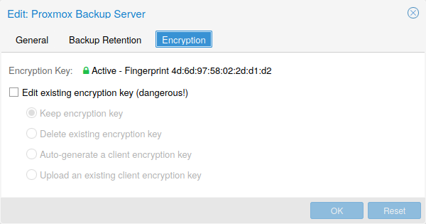
Optionally, you can configure client-side encryption with AES-256 in GCM mode. Encryption can be configured either via the web interface, or on the CLI with the encryption-key option (see above). The key will be saved in the file /etc/pve/priv/storage/<STORAGE-ID>.enc, which is only accessible by the root user.
|
|
Without their key, backups will be inaccessible. Thus, you should keep keys ordered and in a place that is separate from the contents being backed up. It can happen, for example, that you back up an entire system, using a key on that system. If the system then becomes inaccessible for any reason and needs to be restored, this will not be possible as the encryption key will be lost along with the broken system. |
It is recommended that you keep your key safe, but easily accessible, in order for quick disaster recovery. For this reason, the best place to store it is in your password manager, where it is immediately recoverable. As a backup to this, you should also save the key to a USB flash drive and store that in a secure place. This way, it is detached from any system, but is still easy to recover from, in case of emergency. Finally, in preparation for the worst case scenario, you should also consider keeping a paper copy of your key locked away in a safe place. The paperkey subcommand can be used to create a QR encoded version of your key. The following command sends the output of the paperkey command to a text file, for easy printing.
# proxmox-backup-client key paperkey /etc/pve/priv/storage/<STORAGE-ID>.enc --output-format text > qrkey.txt
Additionally, it is possible to use a single RSA master key pair for key recovery purposes: configure all clients doing encrypted backups to use a single public master key, and all subsequent encrypted backups will contain a RSA-encrypted copy of the used AES encryption key. The corresponding private master key allows recovering the AES key and decrypting the backup even if the client system is no longer available.
|
|
The same safe-keeping rules apply to the master key pair as to the regular encryption keys. Without a copy of the private key recovery is not possible! The paperkey command supports generating paper copies of private master keys for storage in a safe, physical location. |
Because the encryption is managed on the client side, you can use the same datastore on the server for unencrypted backups and encrypted backups, even if they are encrypted with different keys. However, deduplication between backups with different keys is not possible, so it is often better to create separate datastores.
|
|
Do not use encryption if there is no benefit from it, for example, when you are running the server locally in a trusted network. It is always easier to recover from unencrypted backups. |
7.8.4. Example: Add Storage over CLI
Then you could add this share as a storage to the whole Proxmox VE cluster with:
# pvesm add pbs <id> --server <server> --datastore <datastore> --username <username> --fingerprint 00:B4:... --password
7.9. GlusterFS Backend
Storage pool type: glusterfs
GlusterFS is a scalable network file system. The system uses a modular design, runs on commodity hardware, and can provide a highly available enterprise storage at low costs. Such system is capable of scaling to several petabytes, and can handle thousands of clients.
|
|
After a node/brick crash, GlusterFS does a full rsync to make sure data is consistent. This can take a very long time with large files, so this backend is not suitable to store large VM images. |
7.9.1. Configuration
The backend supports all common storage properties, and adds the following GlusterFS specific options:
- server
-
GlusterFS volfile server IP or DNS name.
- server2
-
Backup volfile server IP or DNS name.
- volume
-
GlusterFS Volume.
- transport
-
GlusterFS transport: tcp, unix or rdma
glusterfs: Gluster
        server 10.2.3.4
        server2 10.2.3.5
        volume glustervol
        content images,iso
7.9.2. File naming conventions
The directory layout and the file naming conventions are inherited from the dir backend.
7.9.3. Storage Features
The storage provides a file level interface, but no native snapshot/clone implementation.
| Content types | Image formats | Shared | Snapshots | Clones |
|---|---|---|---|---|
images vztmpl iso backup snippets |
raw qcow2 vmdk |
yes |
qcow2 |
qcow2 |
7.10. Local ZFS Pool Backend
Storage pool type: zfspool
This backend allows you to access local ZFS pools (or ZFS file systems inside such pools).
7.10.1. Configuration
The backend supports the common storage properties content, nodes, disable, and the following ZFS specific properties:
- pool
-
Select the ZFS pool/filesystem. All allocations are done within that pool.
- blocksize
-
Set ZFS blocksize parameter.
- sparse
-
Use ZFS thin-provisioning. A sparse volume is a volume whose reservation is not equal to the volume size.
- mountpoint
-
The mount point of the ZFS pool/filesystem. Changing this does not affect the mountpoint property of the dataset seen by zfs. Defaults to /<pool>.
zfspool: vmdata
        pool tank/vmdata
        content rootdir,images
        sparse
7.10.2. File naming conventions
The backend uses the following naming scheme for VM images:
vm-<VMID>-<NAME>      // normal VM images
base-<VMID>-<NAME>    // template VM image (read-only)
subvol-<VMID>-<NAME>  // subvolumes (ZFS filesystem for containers)
- <VMID>
-
This specifies the owner VM.
- <NAME>
-
This can be an arbitrary name (ascii) without white space. The backend uses disk[N] as default, where [N] is replaced by an integer to make the name unique.
7.10.3. Storage Features
ZFS is probably the most advanced storage type regarding snapshot and cloning. The backend uses ZFS datasets for both VM images (format raw) and container data (format subvol). ZFS properties are inherited from the parent dataset, so you can simply set defaults on the parent dataset.
| Content types | Image formats | Shared | Snapshots | Clones |
|---|---|---|---|---|
images rootdir |
raw subvol |
no |
yes |
yes |
7.10.4. Examples
It is recommended to create an extra ZFS file system to store your VM images:
# zfs create tank/vmdata
To enable compression on that newly allocated file system:
# zfs set compression=on tank/vmdata
You can get a list of available ZFS filesystems with:
# pvesm zfsscan
7.11. LVM Backend
Storage pool type: lvm
LVM is a light software layer on top of hard disks and partitions. It can be used to split available disk space into smaller logical volumes. LVM is widely used on Linux and makes managing hard drives easier.
Another use case is to put LVM on top of a big iSCSI LUN. That way you can easily manage space on that iSCSI LUN, which would not be possible otherwise, because the iSCSI specification does not define a management interface for space allocation.
7.11.1. Configuration
The LVM backend supports the common storage properties content, nodes, disable, and the following LVM specific properties:
- vgname
-
LVM volume group name. This must point to an existing volume group.
- base
-
Base volume. This volume is automatically activated before accessing the storage. This is mostly useful when the LVM volume group resides on a remote iSCSI server.
- saferemove
-
Called "Wipe Removed Volumes" in the web UI. Zero-out data when removing LVs. When removing a volume, this makes sure that all data gets erased and cannot be accessed by other LVs created later (which happen to be assigned the same physical extents). This is a costly operation, but may be required as a security measure in certain environments.
- saferemove_throughput
-
Wipe throughput (cstream -t parameter value).
lvm: myspace
        vgname myspace
        content rootdir,images
7.11.2. File naming conventions
The backend use basically the same naming conventions as the ZFS pool backend.
vm-<VMID>-<NAME> // normal VM images
7.11.3. Storage Features
LVM is a typical block storage, but this backend does not support snapshots and clones. Unfortunately, normal LVM snapshots are quite inefficient, because they interfere with all writes on the entire volume group during snapshot time.
One big advantage is that you can use it on top of a shared storage, for example, an iSCSI LUN. The backend itself implements proper cluster-wide locking.
|
|
The newer LVM-thin backend allows snapshots and clones, but does not support shared storage. |
| Content types | Image formats | Shared | Snapshots | Clones |
|---|---|---|---|---|
images rootdir |
raw |
possible |
no |
no |
7.11.4. Examples
List available volume groups:
# pvesm lvmscan
7.12. LVM thin Backend
Storage pool type: lvmthin
LVM normally allocates blocks when you create a volume. LVM thin pools instead allocates blocks when they are written. This behaviour is called thin-provisioning, because volumes can be much larger than physically available space.
You can use the normal LVM command-line tools to manage and create LVM thin pools (see man lvmthin for details). Assuming you already have a LVM volume group called pve, the following commands create a new LVM thin pool (size 100G) called data:
lvcreate -L 100G -n data pve
lvconvert --type thin-pool pve/data
7.12.1. Configuration
The LVM thin backend supports the common storage properties content, nodes, disable, and the following LVM specific properties:
- vgname
-
LVM volume group name. This must point to an existing volume group.
- thinpool
-
The name of the LVM thin pool.
lvmthin: local-lvm
        thinpool data
        vgname pve
        content rootdir,images
7.12.2. File naming conventions
The backend use basically the same naming conventions as the ZFS pool backend.
vm-<VMID>-<NAME> // normal VM images
7.12.3. Storage Features
LVM thin is a block storage, but fully supports snapshots and clones efficiently. New volumes are automatically initialized with zero.
It must be mentioned that LVM thin pools cannot be shared across multiple nodes, so you can only use them as local storage.
| Content types | Image formats | Shared | Snapshots | Clones |
|---|---|---|---|---|
images rootdir |
raw |
no |
yes |
yes |
7.12.4. Examples
List available LVM thin pools on volume group pve:
# pvesm lvmthinscan pve
7.13. Open-iSCSI initiator
Storage pool type: iscsi
iSCSI is a widely employed technology used to connect to storage servers. Almost all storage vendors support iSCSI. There are also open source iSCSI target solutions available, e.g. OpenMediaVault, which is based on Debian.
To use this backend, you need to install the Open-iSCSI (open-iscsi) package. This is a standard Debian package, but it is not installed by default to save resources.
# apt-get install open-iscsi
Low-level iscsi management task can be done using the iscsiadm tool.
7.13.1. Configuration
The backend supports the common storage properties content, nodes, disable, and the following iSCSI specific properties:
- portal
-
iSCSI portal (IP or DNS name with optional port).
- target
-
iSCSI target.
iscsi: mynas
     portal 10.10.10.1
     target iqn.2006-01.openfiler.com:tsn.dcb5aaaddd
     content none
|
|
If you want to use LVM on top of iSCSI, it make sense to set content none. That way it is not possible to create VMs using iSCSI LUNs directly. |
7.13.2. File naming conventions
The iSCSI protocol does not define an interface to allocate or delete data. Instead, that needs to be done on the target side and is vendor specific. The target simply exports them as numbered LUNs. So Proxmox VE iSCSI volume names just encodes some information about the LUN as seen by the linux kernel.
7.13.3. Storage Features
iSCSI is a block level type storage, and provides no management interface. So it is usually best to export one big LUN, and setup LVM on top of that LUN. You can then use the LVM plugin to manage the storage on that iSCSI LUN.
| Content types | Image formats | Shared | Snapshots | Clones |
|---|---|---|---|---|
images none |
raw |
yes |
no |
no |
7.13.4. Examples
Scan a remote iSCSI portal, and returns a list of possible targets:
pvesm scan iscsi <HOST[:PORT]>
7.14. User Mode iSCSI Backend
Storage pool type: iscsidirect
This backend provides basically the same functionality as the Open-iSCSI backed, but uses a user-level library to implement it. You need to install the libiscsi-bin package in order to use this backend.
It should be noted that there are no kernel drivers involved, so this can be viewed as performance optimization. But this comes with the drawback that you cannot use LVM on top of such iSCSI LUN. So you need to manage all space allocations at the storage server side.
7.14.1. Configuration
The user mode iSCSI backend uses the same configuration options as the Open-iSCSI backed.
iscsidirect: faststore
     portal 10.10.10.1
     target iqn.2006-01.openfiler.com:tsn.dcb5aaaddd
7.14.2. Storage Features
|
|
This backend works with VMs only. Containers cannot use this driver. |
| Content types | Image formats | Shared | Snapshots | Clones |
|---|---|---|---|---|
images |
raw |
yes |
no |
no |
7.15. Ceph RADOS Block Devices (RBD)
Storage pool type: rbd
Ceph is a distributed object store and file system designed to provide excellent performance, reliability and scalability. RADOS block devices implement a feature rich block level storage, and you get the following advantages:
-
thin provisioning
-
resizable volumes
-
distributed and redundant (striped over multiple OSDs)
-
full snapshot and clone capabilities
-
self healing
-
no single point of failure
-
scalable to the exabyte level
-
kernel and user space implementation available
|
|
For smaller deployments, it is also possible to run Ceph services directly on your Proxmox VE nodes. Recent hardware has plenty of CPU power and RAM, so running storage services and VMs on same node is possible. |
7.15.1. Configuration
This backend supports the common storage properties nodes, disable, content, and the following rbd specific properties:
- monhost
-
List of monitor daemon IPs. Optional, only needed if Ceph is not running on the Proxmox VE cluster.
- pool
-
Ceph pool name.
- username
-
RBD user ID. Optional, only needed if Ceph is not running on the Proxmox VE cluster. Note that only the user ID should be used. The "client." type prefix must be left out.
- krbd
-
Enforce access to rados block devices through the krbd kernel module. Optional.
|
|
Containers will use krbd independent of the option value. |
rbd: ceph-external
        monhost 10.1.1.20 10.1.1.21 10.1.1.22
        pool ceph-external
        content images
        username admin
|
|
You can use the rbd utility to do low-level management tasks. |
7.15.2. Authentication
|
|
If Ceph is installed locally on the Proxmox VE cluster, the following is done automatically when adding the storage. |
If you use cephx authentication, which is enabled by default, you need to provide the keyring from the external Ceph cluster.
To configure the storage via the CLI, you first need to make the file containing the keyring available. One way is to copy the file from the external Ceph cluster directly to one of the Proxmox VE nodes. The following example will copy it to the /root directory of the node on which we run it:
# scp <external cephserver>:/etc/ceph/ceph.client.admin.keyring /root/rbd.keyring
Then use the pvesm CLI tool to configure the external RBD storage, use the --keyring parameter, which needs to be a path to the keyring file that you copied. For example:
# pvesm add rbd <name> --monhost "10.1.1.20 10.1.1.21 10.1.1.22" --content images --keyring /root/rbd.keyring
When configuring an external RBD storage via the GUI, you can copy and paste the keyring into the appropriate field.
The keyring will be stored at
# /etc/pve/priv/ceph/<STORAGE_ID>.keyring
|
|
Creating a keyring with only the needed capabilities is recommend when
connecting to an external cluster. For further information on Ceph user
management, see the Ceph docs. [Ceph User Management] |
7.15.3. Ceph client configuration (optional)
Connecting to an external Ceph storage doesn’t always allow setting client-specific options in the config DB on the external cluster. You can add a ceph.conf beside the Ceph keyring to change the Ceph client configuration for the storage.
The ceph.conf needs to have the same name as the storage.
# /etc/pve/priv/ceph/<STORAGE_ID>.conf
See the RBD configuration reference
[RBD configuration reference
https://docs.ceph.com/en/quincy/rbd/rbd-config-ref/]
for possible settings.
|
|
Do not change these settings lightly. Proxmox VE is merging the <STORAGE_ID>.conf with the storage configuration. |
7.15.4. Storage Features
The rbd backend is a block level storage, and implements full snapshot and clone functionality.
| Content types | Image formats | Shared | Snapshots | Clones |
|---|---|---|---|---|
images rootdir |
raw |
yes |
yes |
yes |
7.16. Ceph Filesystem (CephFS)
Storage pool type: cephfs
CephFS implements a POSIX-compliant filesystem, using a Ceph storage cluster to store its data. As CephFS builds upon Ceph, it shares most of its properties. This includes redundancy, scalability, self-healing, and high availability.
|
|
Proxmox VE can manage Ceph setups, which makes configuring a CephFS storage easier. As modern hardware offers a lot of processing power and RAM, running storage services and VMs on same node is possible without a significant performance impact. |
To use the CephFS storage plugin, you must replace the stock Debian Ceph client, by adding our Ceph repository. Once added, run apt update, followed by apt dist-upgrade, in order to get the newest packages.
|
|
Please ensure that there are no other Ceph repositories configured. Otherwise the installation will fail or there will be mixed package versions on the node, leading to unexpected behavior. |
7.16.1. Configuration
This backend supports the common storage properties nodes, disable, content, as well as the following cephfs specific properties:
- fs-name
-
Name of the Ceph FS.
- monhost
-
List of monitor daemon addresses. Optional, only needed if Ceph is not running on the Proxmox VE cluster.
- path
-
The local mount point. Optional, defaults to /mnt/pve/<STORAGE_ID>/.
- username
-
Ceph user id. Optional, only needed if Ceph is not running on the Proxmox VE cluster, where it defaults to admin.
- subdir
-
CephFS subdirectory to mount. Optional, defaults to /.
- fuse
-
Access CephFS through FUSE, instead of the kernel client. Optional, defaults to 0.
cephfs: cephfs-external
        monhost 10.1.1.20 10.1.1.21 10.1.1.22
        path /mnt/pve/cephfs-external
        content backup
        username admin
        fs-name cephfs
|
|
Don’t forget to set up the client’s secret key file, if cephx was not disabled. |
7.16.2. Authentication
|
|
If Ceph is installed locally on the Proxmox VE cluster, the following is done automatically when adding the storage. |
If you use cephx authentication, which is enabled by default, you need to provide the secret from the external Ceph cluster.
To configure the storage via the CLI, you first need to make the file containing the secret available. One way is to copy the file from the external Ceph cluster directly to one of the Proxmox VE nodes. The following example will copy it to the /root directory of the node on which we run it:
# scp <external cephserver>:/etc/ceph/cephfs.secret /root/cephfs.secret
Then use the pvesm CLI tool to configure the external RBD storage, use the --keyring parameter, which needs to be a path to the secret file that you copied. For example:
# pvesm add cephfs <name> --monhost "10.1.1.20 10.1.1.21 10.1.1.22" --content backup --keyring /root/cephfs.secret
When configuring an external RBD storage via the GUI, you can copy and paste the secret into the appropriate field.
The secret is only the key itself, as opposed to the rbd backend which also contains a [client.userid] section.
The secret will be stored at
# /etc/pve/priv/ceph/<STORAGE_ID>.secret
A secret can be received from the Ceph cluster (as Ceph admin) by issuing the
command below, where userid is the client ID that has been configured to
access the cluster. For further information on Ceph user management, see the
Ceph docs.
[cephusermgmt]
# ceph auth get-key client.userid > cephfs.secret
7.16.3. Storage Features
The cephfs backend is a POSIX-compliant filesystem, on top of a Ceph cluster.
| Content types | Image formats | Shared | Snapshots | Clones |
|---|---|---|---|---|
vztmpl iso backup snippets |
none |
yes |
yes[1] |
no |
[1] While no known bugs exist, snapshots are not yet guaranteed to be stable, as they lack sufficient testing.
7.17. BTRFS Backend
Storage pool type: btrfs
On the surface, this storage type is very similar to the directory storage type, so see the directory backend section for a general overview.
The main difference is that with this storage type raw formatted disks will be placed in a subvolume, in order to allow taking snapshots and supporting offline storage migration with snapshots being preserved.
|
|
BTRFS will honor the O_DIRECT flag when opening files, meaning VMs should not use cache mode none, otherwise there will be checksum errors. |
7.17.1. Configuration
This backend is configured similarly to the directory storage. Note that when adding a directory as a BTRFS storage, which is not itself also the mount point, it is highly recommended to specify the actual mount point via the is_mountpoint option.
For example, if a BTRFS file system is mounted at /mnt/data2 and its pve-storage/ subdirectory (which may be a snapshot, which is recommended) should be added as a storage pool called data2, you can use the following entry:
btrfs: data2
        path /mnt/data2/pve-storage
        content rootdir,images
        is_mountpoint /mnt/data2
7.17.2. Snapshots
When taking a snapshot of a subvolume or raw file, the snapshot will be created as a read-only subvolume with the same path followed by an @ and the snapshot’s name.
7.18. ZFS over ISCSI Backend
Storage pool type: zfs
This backend accesses a remote machine having a ZFS pool as storage and an iSCSI target implementation via ssh. For each guest disk it creates a ZVOL and, exports it as iSCSI LUN. This LUN is used by Proxmox VE for the guest disk.
The following iSCSI target implementations are supported:
-
LIO (Linux)
-
IET (Linux)
-
ISTGT (FreeBSD)
-
Comstar (Solaris)
|
|
This plugin needs a ZFS capable remote storage appliance, you cannot use it to create a ZFS Pool on a regular Storage Appliance/SAN |
7.18.1. Configuration
In order to use the ZFS over iSCSI plugin you need to configure the remote machine (target) to accept ssh connections from the Proxmox VE node. Proxmox VE connects to the target for creating the ZVOLs and exporting them via iSCSI. Authentication is done through a ssh-key (without password protection) stored in /etc/pve/priv/zfs/<target_ip>_id_rsa
The following steps create a ssh-key and distribute it to the storage machine with IP 192.0.2.1:
mkdir /etc/pve/priv/zfs
ssh-keygen -f /etc/pve/priv/zfs/192.0.2.1_id_rsa
ssh-copy-id -i /etc/pve/priv/zfs/192.0.2.1_id_rsa.pub root@192.0.2.1
ssh -i /etc/pve/priv/zfs/192.0.2.1_id_rsa root@192.0.2.1
The backend supports the common storage properties content, nodes, disable, and the following ZFS over ISCSI specific properties:
- pool
-
The ZFS pool/filesystem on the iSCSI target. All allocations are done within that pool.
- portal
-
iSCSI portal (IP or DNS name with optional port).
- target
-
iSCSI target.
- iscsiprovider
-
The iSCSI target implementation used on the remote machine
- comstar_tg
-
target group for comstar views.
- comstar_hg
-
host group for comstar views.
- lio_tpg
-
target portal group for Linux LIO targets
- nowritecache
-
disable write caching on the target
- blocksize
-
Set ZFS blocksize parameter.
- sparse
-
Use ZFS thin-provisioning. A sparse volume is a volume whose reservation is not equal to the volume size.
zfs: lio
   blocksize 4k
   iscsiprovider LIO
   pool tank
   portal 192.0.2.111
   target iqn.2003-01.org.linux-iscsi.lio.x8664:sn.xxxxxxxxxxxx
   content images
   lio_tpg tpg1
   sparse 1

zfs: solaris
   blocksize 4k
   target iqn.2010-08.org.illumos:02:xxxxxxxx-xxxx-xxxx-xxxx-xxxxxxxxxxxx:tank1
   pool tank
   iscsiprovider comstar
   portal 192.0.2.112
   content images

zfs: freebsd
   blocksize 4k
   target iqn.2007-09.jp.ne.peach.istgt:tank1
   pool tank
   iscsiprovider istgt
   portal 192.0.2.113
   content images

zfs: iet
   blocksize 4k
   target iqn.2001-04.com.example:tank1
   pool tank
   iscsiprovider iet
   portal 192.0.2.114
   content images
7.18.2. Storage Features
The ZFS over iSCSI plugin provides a shared storage, which is capable of snapshots. You need to make sure that the ZFS appliance does not become a single point of failure in your deployment.
| Content types | Image formats | Shared | Snapshots | Clones |
|---|---|---|---|---|
images |
raw |
yes |
yes |
no |
8. Deploy Hyper-Converged Ceph Cluster
8.1. Introduction
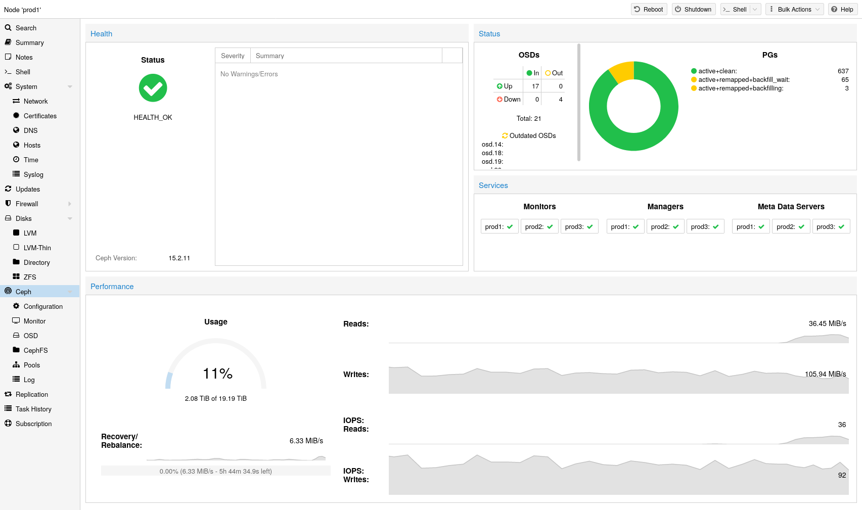
Proxmox VE unifies your compute and storage systems, that is, you can use the same physical nodes within a cluster for both computing (processing VMs and containers) and replicated storage. The traditional silos of compute and storage resources can be wrapped up into a single hyper-converged appliance. Separate storage networks (SANs) and connections via network attached storage (NAS) disappear. With the integration of Ceph, an open source software-defined storage platform, Proxmox VE has the ability to run and manage Ceph storage directly on the hypervisor nodes.
Ceph is a distributed object store and file system designed to provide excellent performance, reliability and scalability.
-
Easy setup and management via CLI and GUI
-
Thin provisioning
-
Snapshot support
-
Self healing
-
Scalable to the exabyte level
-
Provides block, file system, and object storage
-
Setup pools with different performance and redundancy characteristics
-
Data is replicated, making it fault tolerant
-
Runs on commodity hardware
-
No need for hardware RAID controllers
-
Open source
For small to medium-sized deployments, it is possible to install a Ceph server for using RADOS Block Devices (RBD) or CephFS directly on your Proxmox VE cluster nodes (see Ceph RADOS Block Devices (RBD)). Recent hardware has a lot of CPU power and RAM, so running storage services and virtual guests on the same node is possible.
To simplify management, Proxmox VE provides you native integration to install and manage Ceph services on Proxmox VE nodes either via the built-in web interface, or using the pveceph command line tool.
8.2. Terminology
-
Ceph Monitor (ceph-mon, or MON)
-
Ceph Manager (ceph-mgr, or MGS)
-
Ceph Metadata Service (ceph-mds, or MDS)
-
Ceph Object Storage Daemon (ceph-osd, or OSD)
|
|
We highly recommend to get familiar with Ceph
[Ceph intro https://docs.ceph.com/en/quincy/start/intro/] , its architecture [Ceph architecture https://docs.ceph.com/en/quincy/architecture/] and vocabulary [Ceph glossary https://docs.ceph.com/en/quincy/glossary] . |
8.3. Recommendations for a Healthy Ceph Cluster
To build a hyper-converged Proxmox + Ceph Cluster, you must use at least three (preferably) identical servers for the setup.
Check also the recommendations from Ceph’s website.
|
|
The recommendations below should be seen as a rough guidance for choosing hardware. Therefore, it is still essential to adapt it to your specific needs. You should test your setup and monitor health and performance continuously. |
Ceph services can be classified into two categories: * Intensive CPU usage, benefiting from high CPU base frequencies and multiple cores. Members of that category are: Object Storage Daemon (OSD) services Meta Data Service (MDS) used for CephFS * Moderate CPU usage, not needing multiple CPU cores. These are: Monitor (MON) services Manager (MGR) services
As a simple rule of thumb, you should assign at least one CPU core (or thread) to each Ceph service to provide the minimum resources required for stable and durable Ceph performance.
For example, if you plan to run a Ceph monitor, a Ceph manager and 6 Ceph OSDs services on a node you should reserve 8 CPU cores purely for Ceph when targeting basic and stable performance.
Note that OSDs CPU usage depend mostly from the disks performance. The higher the possible IOPS (IO Operations per Second) of a disk, the more CPU can be utilized by a OSD service. For modern enterprise SSD disks, like NVMe’s that can permanently sustain a high IOPS load over 100’000 with sub millisecond latency, each OSD can use multiple CPU threads, e.g., four to six CPU threads utilized per NVMe backed OSD is likely for very high performance disks.
Especially in a hyper-converged setup, the memory consumption needs to be carefully planned out and monitored. In addition to the predicted memory usage of virtual machines and containers, you must also account for having enough memory available for Ceph to provide excellent and stable performance.
As a rule of thumb, for roughly 1 TiB of data, 1 GiB of memory will be used by an OSD. While the usage might be less under normal conditions, it will use most during critical operations like recovery, re-balancing or backfilling. That means that you should avoid maxing out your available memory already on normal operation, but rather leave some headroom to cope with outages.
The OSD service itself will use additional memory. The Ceph BlueStore backend of the daemon requires by default 3-5 GiB of memory (adjustable).
We recommend a network bandwidth of at least 10 Gbps, or more, to be used
exclusively for Ceph traffic. A meshed network setup
[Full Mesh Network for Ceph https://pve.proxmox.com/wiki/Full_Mesh_Network_for_Ceph_Server]
is also an option for three to five node clusters, if there are no 10+ Gbps
switches available.
|
|
The volume of traffic, especially during recovery, will interfere with other services on the same network, especially the latency sensitive Proxmox VE corosync cluster stack can be affected, resulting in possible loss of cluster quorum. Moving the Ceph traffic to dedicated and physical separated networks will avoid such interference, not only for corosync, but also for the networking services provided by any virtual guests. |
For estimating your bandwidth needs, you need to take the performance of your disks into account.. While a single HDD might not saturate a 1 Gb link, multiple HDD OSDs per node can already saturate 10 Gbps too. If modern NVMe-attached SSDs are used, a single one can already saturate 10 Gbps of bandwidth, or more. For such high-performance setups we recommend at least a 25 Gpbs, while even 40 Gbps or 100+ Gbps might be required to utilize the full performance potential of the underlying disks.
If unsure, we recommend using three (physical) separate networks for high-performance setups: * one very high bandwidth (25+ Gbps) network for Ceph (internal) cluster traffic. * one high bandwidth (10+ Gpbs) network for Ceph (public) traffic between the ceph server and ceph client storage traffic. Depending on your needs this can also be used to host the virtual guest traffic and the VM live-migration traffic. * one medium bandwidth (1 Gbps) exclusive for the latency sensitive corosync cluster communication.
When planning the size of your Ceph cluster, it is important to take the recovery time into consideration. Especially with small clusters, recovery might take long. It is recommended that you use SSDs instead of HDDs in small setups to reduce recovery time, minimizing the likelihood of a subsequent failure event during recovery.
In general, SSDs will provide more IOPS than spinning disks. With this in mind, in addition to the higher cost, it may make sense to implement a class based separation of pools. Another way to speed up OSDs is to use a faster disk as a journal or DB/Write-Ahead-Log device, see creating Ceph OSDs. If a faster disk is used for multiple OSDs, a proper balance between OSD and WAL / DB (or journal) disk must be selected, otherwise the faster disk becomes the bottleneck for all linked OSDs.
Aside from the disk type, Ceph performs best with an evenly sized, and an evenly distributed amount of disks per node. For example, 4 x 500 GB disks within each node is better than a mixed setup with a single 1 TB and three 250 GB disk.
You also need to balance OSD count and single OSD capacity. More capacity allows you to increase storage density, but it also means that a single OSD failure forces Ceph to recover more data at once.
As Ceph handles data object redundancy and multiple parallel writes to disks (OSDs) on its own, using a RAID controller normally doesn’t improve performance or availability. On the contrary, Ceph is designed to handle whole disks on it’s own, without any abstraction in between. RAID controllers are not designed for the Ceph workload and may complicate things and sometimes even reduce performance, as their write and caching algorithms may interfere with the ones from Ceph.
|
|
Avoid RAID controllers. Use host bus adapter (HBA) instead. |
8.4. Initial Ceph Installation & Configuration
8.4.1. Using the Web-based Wizard
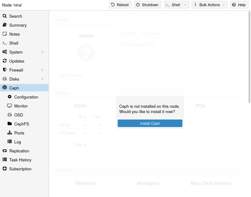
With Proxmox VE you have the benefit of an easy to use installation wizard for Ceph. Click on one of your cluster nodes and navigate to the Ceph section in the menu tree. If Ceph is not already installed, you will see a prompt offering to do so.
The wizard is divided into multiple sections, where each needs to finish successfully, in order to use Ceph.
First you need to chose which Ceph version you want to install. Prefer the one from your other nodes, or the newest if this is the first node you install Ceph.
After starting the installation, the wizard will download and install all the required packages from Proxmox VE’s Ceph repository.
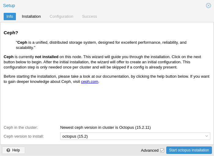
After finishing the installation step, you will need to create a configuration. This step is only needed once per cluster, as this configuration is distributed automatically to all remaining cluster members through Proxmox VE’s clustered configuration file system (pmxcfs).
The configuration step includes the following settings:
-
Public Network: This network will be used for public storage communication (e.g., for virtual machines using a Ceph RBD backed disk, or a CephFS mount), and communication between the different Ceph services. This setting is required.
Separating your Ceph traffic from the Proxmox VE cluster communication (corosync), and possible the front-facing (public) networks of your virtual guests, is highly recommended. Otherwise, Ceph’s high-bandwidth IO-traffic could cause interference with other low-latency dependent services. -
Cluster Network: Specify to separate the OSD replication and heartbeat traffic as well. This setting is optional.
Using a physically separated network is recommended, as it will relieve the Ceph public and the virtual guests network, while also providing a significant Ceph performance improvements.
The Ceph cluster network can be configured and moved to another physically separated network at a later time.
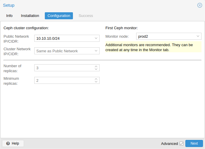
You have two more options which are considered advanced and therefore should only changed if you know what you are doing.
-
Number of replicas: Defines how often an object is replicated.
-
Minimum replicas: Defines the minimum number of required replicas for I/O to be marked as complete.
Additionally, you need to choose your first monitor node. This step is required.
That’s it. You should now see a success page as the last step, with further instructions on how to proceed. Your system is now ready to start using Ceph. To get started, you will need to create some additional monitors, OSDs and at least one pool.
The rest of this chapter will guide you through getting the most out of your Proxmox VE based Ceph setup. This includes the aforementioned tips and more, such as CephFS, which is a helpful addition to your new Ceph cluster.
8.4.2. CLI Installation of Ceph Packages
Alternatively to the the recommended Proxmox VE Ceph installation wizard available in the web interface, you can use the following CLI command on each node:
pveceph install
This sets up an apt package repository in /etc/apt/sources.list.d/ceph.list and installs the required software.
8.4.3. Initial Ceph configuration via CLI
Use the Proxmox VE Ceph installation wizard (recommended) or run the following command on one node:
pveceph init --network 10.10.10.0/24
This creates an initial configuration at /etc/pve/ceph.conf with a dedicated network for Ceph. This file is automatically distributed to all Proxmox VE nodes, using pmxcfs. The command also creates a symbolic link at /etc/ceph/ceph.conf, which points to that file. Thus, you can simply run Ceph commands without the need to specify a configuration file.
8.5. Ceph Monitor
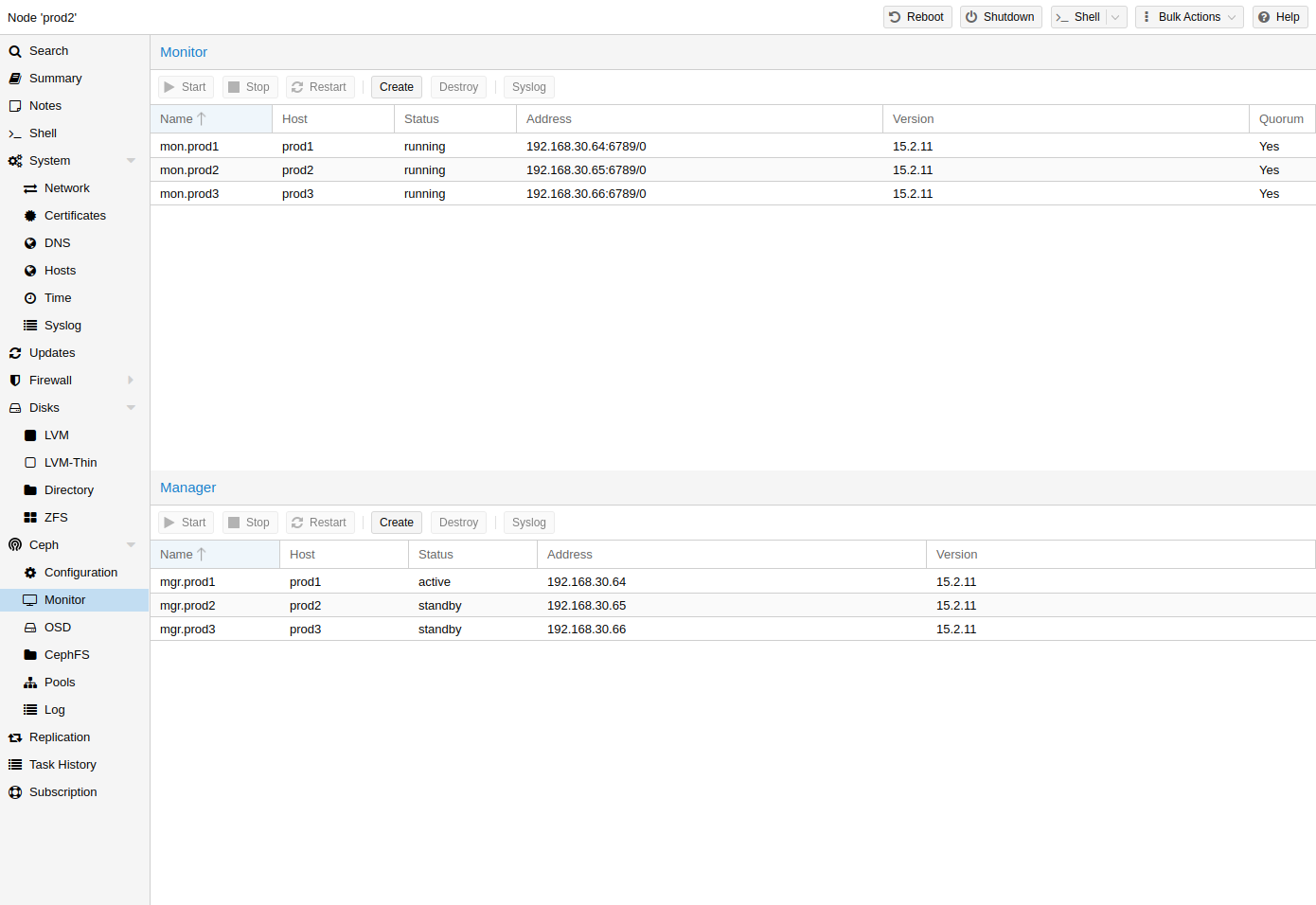
The Ceph Monitor (MON)
[Ceph Monitor https://docs.ceph.com/en/quincy/start/intro/]
maintains a master copy of the cluster map. For high availability, you need at
least 3 monitors. One monitor will already be installed if you
used the installation wizard. You won’t need more than 3 monitors, as long
as your cluster is small to medium-sized. Only really large clusters will
require more than this.
8.5.1. Create Monitors
On each node where you want to place a monitor (three monitors are recommended), create one by using the Ceph → Monitor tab in the GUI or run:
pveceph mon create
8.5.2. Destroy Monitors
To remove a Ceph Monitor via the GUI, first select a node in the tree view and go to the Ceph → Monitor panel. Select the MON and click the Destroy button.
To remove a Ceph Monitor via the CLI, first connect to the node on which the MON is running. Then execute the following command:
pveceph mon destroy
|
|
At least three Monitors are needed for quorum. |
8.6. Ceph Manager
The Manager daemon runs alongside the monitors. It provides an interface to
monitor the cluster. Since the release of Ceph luminous, at least one ceph-mgr
[Ceph Manager https://docs.ceph.com/en/quincy/mgr/]
daemon is
required.
8.6.1. Create Manager
Multiple Managers can be installed, but only one Manager is active at any given time.
pveceph mgr create
|
|
It is recommended to install the Ceph Manager on the monitor nodes. For high availability install more then one manager. |
8.6.2. Destroy Manager
To remove a Ceph Manager via the GUI, first select a node in the tree view and go to the Ceph → Monitor panel. Select the Manager and click the Destroy button.
To remove a Ceph Monitor via the CLI, first connect to the node on which the Manager is running. Then execute the following command:
pveceph mgr destroy
|
|
While a manager is not a hard-dependency, it is crucial for a Ceph cluster, as it handles important features like PG-autoscaling, device health monitoring, telemetry and more. |
8.7. Ceph OSDs
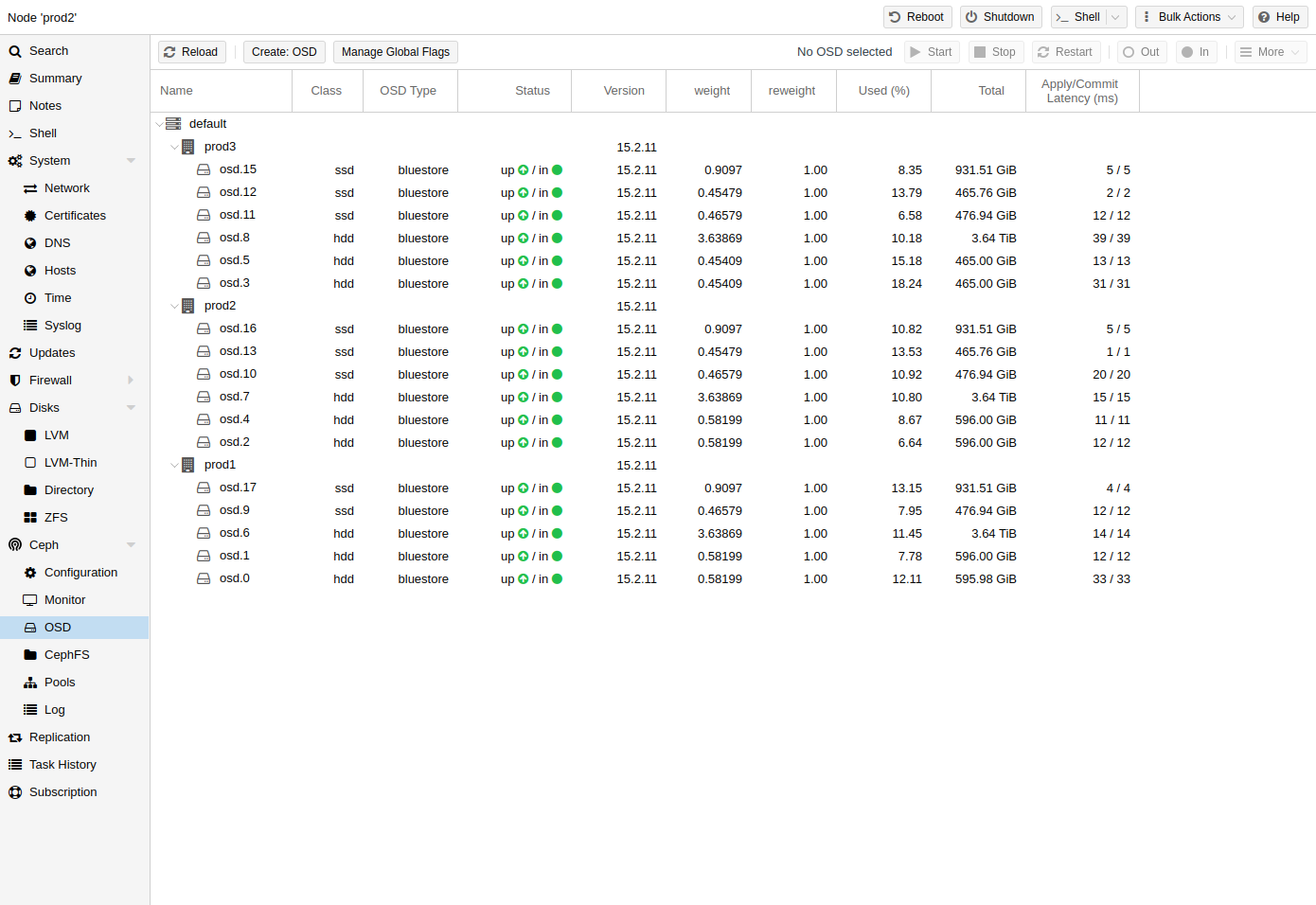
Ceph Object Storage Daemons store objects for Ceph over the network. It is recommended to use one OSD per physical disk.
8.7.1. Create OSDs
You can create an OSD either via the Proxmox VE web interface or via the CLI using pveceph. For example:
pveceph osd create /dev/sd[X]
|
|
We recommend a Ceph cluster with at least three nodes and at least 12 OSDs, evenly distributed among the nodes. |
If the disk was in use before (for example, for ZFS or as an OSD) you first need to zap all traces of that usage. To remove the partition table, boot sector and any other OSD leftover, you can use the following command:
ceph-volume lvm zap /dev/sd[X] --destroy
|
|
The above command will destroy all data on the disk! |
Starting with the Ceph Kraken release, a new Ceph OSD storage type was
introduced called Bluestore
[Ceph Bluestore https://ceph.com/community/new-luminous-bluestore/]
.
This is the default when creating OSDs since Ceph Luminous.
pveceph osd create /dev/sd[X]
If you want to use a separate DB/WAL device for your OSDs, you can specify it through the -db_dev and -wal_dev options. The WAL is placed with the DB, if not specified separately.
pveceph osd create /dev/sd[X] -db_dev /dev/sd[Y] -wal_dev /dev/sd[Z]
You can directly choose the size of those with the -db_size and -wal_size parameters respectively. If they are not given, the following values (in order) will be used:
-
bluestore_block_{db,wal}_size from Ceph configuration…
-
… database, section osd
-
… database, section global
-
… file, section osd
-
… file, section global
-
-
10% (DB)/1% (WAL) of OSD size
|
|
The DB stores BlueStore’s internal metadata, and the WAL is BlueStore’s internal journal or write-ahead log. It is recommended to use a fast SSD or NVRAM for better performance. |
Before Ceph Luminous, Filestore was used as the default storage type for Ceph OSDs. Starting with Ceph Nautilus, Proxmox VE does not support creating such OSDs with pveceph anymore. If you still want to create filestore OSDs, use ceph-volume directly.
ceph-volume lvm create --filestore --data /dev/sd[X] --journal /dev/sd[Y]
8.7.2. Destroy OSDs
To remove an OSD via the GUI, first select a Proxmox VE node in the tree view and go to the Ceph → OSD panel. Then select the OSD to destroy and click the OUT button. Once the OSD status has changed from in to out, click the STOP button. Finally, after the status has changed from up to down, select Destroy from the More drop-down menu.
To remove an OSD via the CLI run the following commands.
ceph osd out <ID>
systemctl stop ceph-osd@<ID>.service
|
|
The first command instructs Ceph not to include the OSD in the data distribution. The second command stops the OSD service. Until this time, no data is lost. |
The following command destroys the OSD. Specify the -cleanup option to additionally destroy the partition table.
pveceph osd destroy <ID>
|
|
The above command will destroy all data on the disk! |
8.8. Ceph Pools
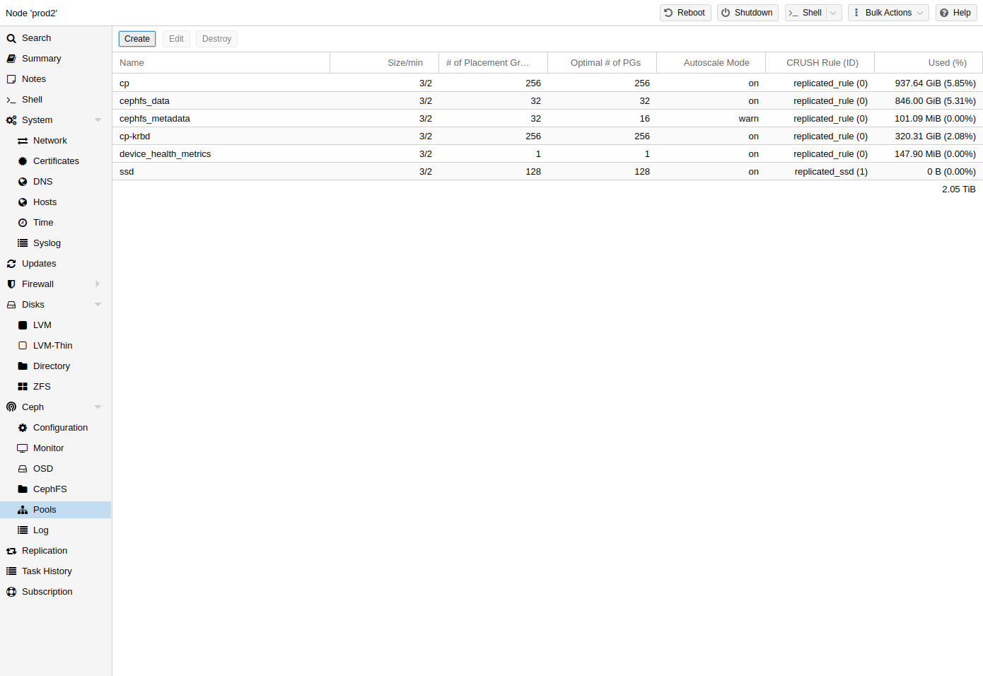
A pool is a logical group for storing objects. It holds a collection of objects, known as Placement Groups (PG, pg_num).
8.8.1. Create and Edit Pools
You can create and edit pools from the command line or the web interface of any Proxmox VE host under Ceph → Pools.
When no options are given, we set a default of 128 PGs, a size of 3 replicas and a min_size of 2 replicas, to ensure no data loss occurs if any OSD fails.
|
|
Do not set a min_size of 1. A replicated pool with min_size of 1 allows I/O on an object when it has only 1 replica, which could lead to data loss, incomplete PGs or unfound objects. |
It is advised that you either enable the PG-Autoscaler or calculate the PG
number based on your setup. You can find the formula and the PG calculator
[PG calculator https://web.archive.org/web/20210301111112/http://ceph.com/pgcalc/]
online. From Ceph Nautilus
onward, you can change the number of PGs
[Placement Groups https://docs.ceph.com/en/quincy/rados/operations/placement-groups/]
after the setup.
The PG autoscaler
[Automated Scaling https://docs.ceph.com/en/quincy/rados/operations/placement-groups/#automated-scaling]
can
automatically scale the PG count for a pool in the background. Setting the
Target Size or Target Ratio advanced parameters helps the PG-Autoscaler to
make better decisions.
pveceph pool create <pool-name> --add_storages
|
|
If you would also like to automatically define a storage for your pool, keep the ‘Add as Storage’ checkbox checked in the web interface, or use the command-line option --add_storages at pool creation. |
Pool Options
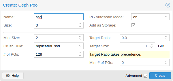
The following options are available on pool creation, and partially also when editing a pool.
- Name
-
The name of the pool. This must be unique and can’t be changed afterwards.
- Size
-
The number of replicas per object. Ceph always tries to have this many copies of an object. Default: 3.
- PG Autoscale Mode
-
The automatic PG scaling mode
[autoscaler]
of the pool. If set to warn, it produces a warning message when a pool has a non-optimal PG count. Default: warn. - Add as Storage
-
Configure a VM or container storage using the new pool. Default: true (only visible on creation).
- Min. Size
-
The minimum number of replicas per object. Ceph will reject I/O on the pool if a PG has less than this many replicas. Default: 2.
- Crush Rule
-
The rule to use for mapping object placement in the cluster. These rules define how data is placed within the cluster. See Ceph CRUSH & device classes for information on device-based rules.
- # of PGs
-
The number of placement groups
[placement_groups]
that the pool should have at the beginning. Default: 128. - Target Ratio
-
The ratio of data that is expected in the pool. The PG autoscaler uses the ratio relative to other ratio sets. It takes precedence over the target size if both are set.
- Target Size
-
The estimated amount of data expected in the pool. The PG autoscaler uses this size to estimate the optimal PG count.
- Min. # of PGs
-
The minimum number of placement groups. This setting is used to fine-tune the lower bound of the PG count for that pool. The PG autoscaler will not merge PGs below this threshold.
Further information on Ceph pool handling can be found in the Ceph pool
operation
[Ceph pool operation
https://docs.ceph.com/en/quincy/rados/operations/pools/]
manual.
8.8.2. Erasure Coded Pools
Erasure coding (EC) is a form of ‘forward error correction’ codes that allows to recover from a certain amount of data loss. Erasure coded pools can offer more usable space compared to replicated pools, but they do that for the price of performance.
For comparison: in classic, replicated pools, multiple replicas of the data are stored (size) while in erasure coded pool, data is split into k data chunks with additional m coding (checking) chunks. Those coding chunks can be used to recreate data should data chunks be missing.
The number of coding chunks, m, defines how many OSDs can be lost without losing any data. The total amount of objects stored is k + m.
Creating EC Pools
Erasure coded (EC) pools can be created with the pveceph CLI tooling. Planning an EC pool needs to account for the fact, that they work differently than replicated pools.
The default min_size of an EC pool depends on the m parameter. If m = 1,
the min_size of the EC pool will be k. The min_size will be k + 1 if
m > 1. The Ceph documentation recommends a conservative min_size of k + 2
[Ceph Erasure Coded Pool Recovery
https://docs.ceph.com/en/quincy/rados/operations/erasure-code/#erasure-coded-pool-recovery]
.
If there are less than min_size OSDs available, any IO to the pool will be blocked until there are enough OSDs available again.
|
|
When planning an erasure coded pool, keep an eye on the min_size as it defines how many OSDs need to be available. Otherwise, IO will be blocked. |
For example, an EC pool with k = 2 and m = 1 will have size = 3, min_size = 2 and will stay operational if one OSD fails. If the pool is configured with k = 2, m = 2, it will have a size = 4 and min_size = 3 and stay operational if one OSD is lost.
To create a new EC pool, run the following command:
pveceph pool create <pool-name> --erasure-coding k=2,m=1
Optional parameters are failure-domain and device-class. If you need to change any EC profile settings used by the pool, you will have to create a new pool with a new profile.
This will create a new EC pool plus the needed replicated pool to store the RBD omap and other metadata. In the end, there will be a <pool name>-data and <pool name>-metada pool. The default behavior is to create a matching storage configuration as well. If that behavior is not wanted, you can disable it by providing the --add_storages 0 parameter. When configuring the storage configuration manually, keep in mind that the data-pool parameter needs to be set. Only then will the EC pool be used to store the data objects. For example:
|
|
The optional parameters --size, --min_size and --crush_rule will be used for the replicated metadata pool, but not for the erasure coded data pool. If you need to change the min_size on the data pool, you can do it later. The size and crush_rule parameters cannot be changed on erasure coded pools. |
If there is a need to further customize the EC profile, you can do so by
creating it with the Ceph tools directly
[Ceph Erasure Code Profile
https://docs.ceph.com/en/quincy/rados/operations/erasure-code/#erasure-code-profiles]
, and
specify the profile to use with the profile parameter.
For example:
pveceph pool create <pool-name> --erasure-coding profile=<profile-name>
Adding EC Pools as Storage
You can add an already existing EC pool as storage to Proxmox VE. It works the same way as adding an RBD pool but requires the extra data-pool option.
pvesm add rbd <storage-name> --pool <replicated-pool> --data-pool <ec-pool>
|
|
Do not forget to add the keyring and monhost option for any external Ceph clusters, not managed by the local Proxmox VE cluster. |
8.8.3. Destroy Pools
To destroy a pool via the GUI, select a node in the tree view and go to the Ceph → Pools panel. Select the pool to destroy and click the Destroy button. To confirm the destruction of the pool, you need to enter the pool name.
Run the following command to destroy a pool. Specify the -remove_storages to also remove the associated storage.
pveceph pool destroy <name>
|
|
Pool deletion runs in the background and can take some time. You will notice the data usage in the cluster decreasing throughout this process. |
8.8.4. PG Autoscaler
The PG autoscaler allows the cluster to consider the amount of (expected) data stored in each pool and to choose the appropriate pg_num values automatically. It is available since Ceph Nautilus.
You may need to activate the PG autoscaler module before adjustments can take effect.
ceph mgr module enable pg_autoscalerThe autoscaler is configured on a per pool basis and has the following modes:
|
warn
|
A health warning is issued if the suggested pg_num value differs too much from the current value. |
|
on
|
The pg_num is adjusted automatically with no need for any manual interaction. |
|
off
|
No automatic pg_num adjustments are made, and no warning will be issued if the PG count is not optimal. |
The scaling factor can be adjusted to facilitate future data storage with the target_size, target_size_ratio and the pg_num_min options.
|
|
By default, the autoscaler considers tuning the PG count of a pool if it is off by a factor of 3. This will lead to a considerable shift in data placement and might introduce a high load on the cluster. |
You can find a more in-depth introduction to the PG autoscaler on Ceph’s Blog - New in Nautilus: PG merging and autotuning.
8.9. Ceph CRUSH & device classes
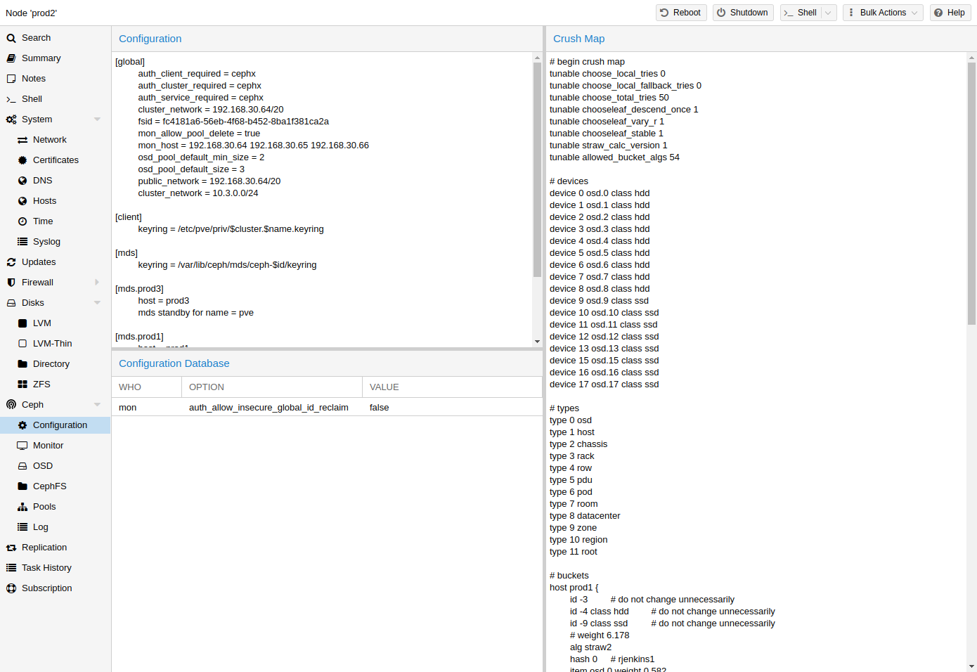
The
[CRUSH
https://ceph.com/wp-content/uploads/2016/08/weil-crush-sc06.pdf]
(Controlled
Replication Under Scalable Hashing) algorithm is at the
foundation of Ceph.
CRUSH calculates where to store and retrieve data from. This has the advantage that no central indexing service is needed. CRUSH works using a map of OSDs, buckets (device locations) and rulesets (data replication) for pools.
|
|
Further information can be found in the Ceph documentation, under the
section CRUSH map [CRUSH map https://docs.ceph.com/en/quincy/rados/operations/crush-map/] . |
This map can be altered to reflect different replication hierarchies. The object replicas can be separated (e.g., failure domains), while maintaining the desired distribution.
A common configuration is to use different classes of disks for different Ceph pools. For this reason, Ceph introduced device classes with luminous, to accommodate the need for easy ruleset generation.
The device classes can be seen in the ceph osd tree output. These classes represent their own root bucket, which can be seen with the below command.
ceph osd crush tree --show-shadow
Example output form the above command:
ID  CLASS WEIGHT  TYPE NAME
-16  nvme 2.18307 root default~nvme
-13  nvme 0.72769     host sumi1~nvme
 12  nvme 0.72769         osd.12
-14  nvme 0.72769     host sumi2~nvme
 13  nvme 0.72769         osd.13
-15  nvme 0.72769     host sumi3~nvme
 14  nvme 0.72769         osd.14
 -1       7.70544 root default
 -3       2.56848     host sumi1
 12  nvme 0.72769         osd.12
 -5       2.56848     host sumi2
 13  nvme 0.72769         osd.13
 -7       2.56848     host sumi3
 14  nvme 0.72769         osd.14
To instruct a pool to only distribute objects on a specific device class, you first need to create a ruleset for the device class:
ceph osd crush rule create-replicated <rule-name> <root> <failure-domain> <class>
<rule-name> |
name of the rule, to connect with a pool (seen in GUI & CLI) |
<root> |
which crush root it should belong to (default Ceph root "default") |
<failure-domain> |
at which failure-domain the objects should be distributed (usually host) |
<class> |
what type of OSD backing store to use (e.g., nvme, ssd, hdd) |
Once the rule is in the CRUSH map, you can tell a pool to use the ruleset.
ceph osd pool set <pool-name> crush_rule <rule-name>
|
|
If the pool already contains objects, these must be moved accordingly. Depending on your setup, this may introduce a big performance impact on your cluster. As an alternative, you can create a new pool and move disks separately. |
8.10. Ceph Client
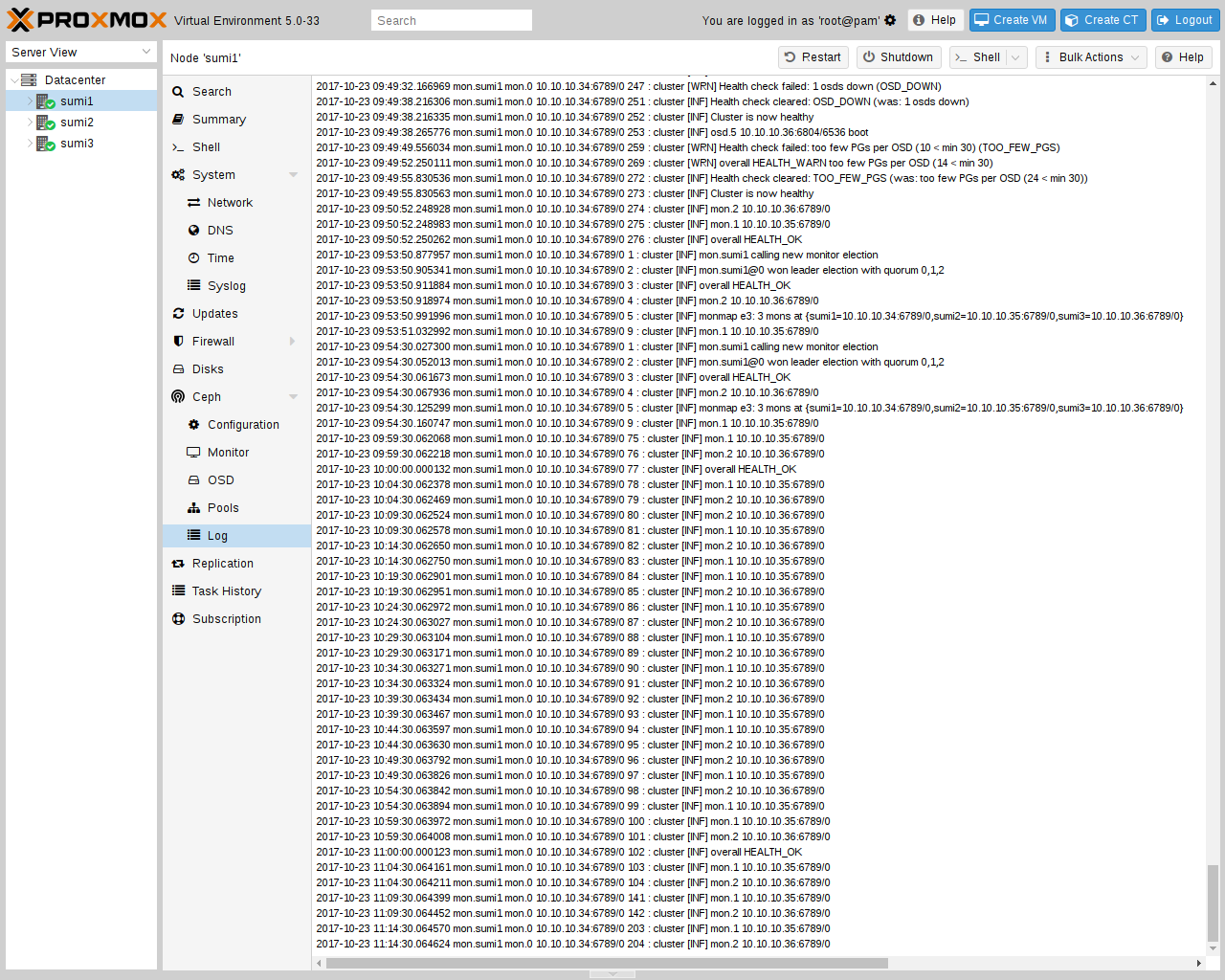
Following the setup from the previous sections, you can configure Proxmox VE to use such pools to store VM and Container images. Simply use the GUI to add a new RBD storage (see section Ceph RADOS Block Devices (RBD)).
You also need to copy the keyring to a predefined location for an external Ceph cluster. If Ceph is installed on the Proxmox nodes itself, then this will be done automatically.
|
|
The filename needs to be <storage_id> + `.keyring, where <storage_id> is the expression after rbd: in /etc/pve/storage.cfg. In the following example, my-ceph-storage is the <storage_id>: |
mkdir /etc/pve/priv/ceph
cp /etc/ceph/ceph.client.admin.keyring /etc/pve/priv/ceph/my-ceph-storage.keyring
8.11. CephFS
Ceph also provides a filesystem, which runs on top of the same object storage as RADOS block devices do. A Metadata Server (MDS) is used to map the RADOS backed objects to files and directories, allowing Ceph to provide a POSIX-compliant, replicated filesystem. This allows you to easily configure a clustered, highly available, shared filesystem. Ceph’s Metadata Servers guarantee that files are evenly distributed over the entire Ceph cluster. As a result, even cases of high load will not overwhelm a single host, which can be an issue with traditional shared filesystem approaches, for example NFS.
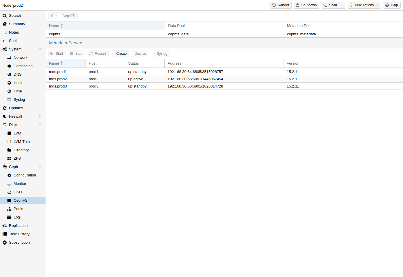
Proxmox VE supports both creating a hyper-converged CephFS and using an existing CephFS as storage to save backups, ISO files, and container templates.
8.11.1. Metadata Server (MDS)
CephFS needs at least one Metadata Server to be configured and running, in order to function. You can create an MDS through the Proxmox VE web GUI’s Node -> CephFS panel or from the command line with:
pveceph mds create
Multiple metadata servers can be created in a cluster, but with the default settings, only one can be active at a time. If an MDS or its node becomes unresponsive (or crashes), another standby MDS will get promoted to active. You can speed up the handover between the active and standby MDS by using the hotstandby parameter option on creation, or if you have already created it you may set/add:
mds standby replay = true
in the respective MDS section of /etc/pve/ceph.conf. With this enabled, the specified MDS will remain in a warm state, polling the active one, so that it can take over faster in case of any issues.
|
|
This active polling will have an additional performance impact on your system and the active MDS. |
Since Luminous (12.2.x) you can have multiple active metadata servers
running at once, but this is normally only useful if you have a high amount of
clients running in parallel. Otherwise the MDS is rarely the bottleneck in a
system. If you want to set this up, please refer to the Ceph documentation.
[Configuring multiple active MDS daemons
https://docs.ceph.com/en/quincy/cephfs/multimds/]
8.11.2. Create CephFS
With Proxmox VE’s integration of CephFS, you can easily create a CephFS using the web interface, CLI or an external API interface. Some prerequisites are required for this to work:
-
Install Ceph packages - if this was already done some time ago, you may want to rerun it on an up-to-date system to ensure that all CephFS related packages get installed.
After this is complete, you can simply create a CephFS through either the Web GUI’s Node -> CephFS panel or the command-line tool pveceph, for example:
pveceph fs create --pg_num 128 --add-storage
This creates a CephFS named cephfs, using a pool for its data named
cephfs_data with 128 placement groups and a pool for its metadata named
cephfs_metadata with one quarter of the data pool’s placement groups (32).
Check the Proxmox VE managed Ceph pool chapter or visit the
Ceph documentation for more information regarding an appropriate placement group
number (pg_num) for your setup
[placement_groups]
.
Additionally, the --add-storage parameter will add the CephFS to the Proxmox VE
storage configuration after it has been created successfully.
8.11.3. Destroy CephFS
|
|
Destroying a CephFS will render all of its data unusable. This cannot be undone! |
To completely and gracefully remove a CephFS, the following steps are necessary:
-
Disconnect every non-Proxmox VE client (e.g. unmount the CephFS in guests).
-
Disable all related CephFS Proxmox VE storage entries (to prevent it from being automatically mounted).
-
Remove all used resources from guests (e.g. ISOs) that are on the CephFS you want to destroy.
-
Unmount the CephFS storages on all cluster nodes manually with
umount /mnt/pve/<STORAGE-NAME>
Where <STORAGE-NAME> is the name of the CephFS storage in your Proxmox VE.
-
Now make sure that no metadata server (MDS) is running for that CephFS, either by stopping or destroying them. This can be done through the web interface or via the command-line interface, for the latter you would issue the following command:
pveceph stop --service mds.NAME
to stop them, or
pveceph mds destroy NAME
to destroy them.
Note that standby servers will automatically be promoted to active when an active MDS is stopped or removed, so it is best to first stop all standby servers.
-
Now you can destroy the CephFS with
pveceph fs destroy NAME --remove-storages --remove-pools
This will automatically destroy the underlying Ceph pools as well as remove the storages from pve config.
After these steps, the CephFS should be completely removed and if you have other CephFS instances, the stopped metadata servers can be started again to act as standbys.
8.12. Ceph maintenance
8.12.1. Replace OSDs
One of the most common maintenance tasks in Ceph is to replace the disk of an OSD. If a disk is already in a failed state, then you can go ahead and run through the steps in Destroy OSDs. Ceph will recreate those copies on the remaining OSDs if possible. This rebalancing will start as soon as an OSD failure is detected or an OSD was actively stopped.
|
|
With the default size/min_size (3/2) of a pool, recovery only starts when ‘size + 1` nodes are available. The reason for this is that the Ceph object balancer CRUSH defaults to a full node as `failure domain’. |
To replace a functioning disk from the GUI, go through the steps in Destroy OSDs. The only addition is to wait until the cluster shows HEALTH_OK before stopping the OSD to destroy it.
On the command line, use the following commands:
ceph osd out osd.<id>
You can check with the command below if the OSD can be safely removed.
ceph osd safe-to-destroy osd.<id>
Once the above check tells you that it is safe to remove the OSD, you can continue with the following commands:
systemctl stop ceph-osd@<id>.service
pveceph osd destroy <id>
Replace the old disk with the new one and use the same procedure as described in Create OSDs.
8.12.2. Trim/Discard
It is good practice to run fstrim (discard) regularly on VMs and containers. This releases data blocks that the filesystem isn’t using anymore. It reduces data usage and resource load. Most modern operating systems issue such discard commands to their disks regularly. You only need to ensure that the Virtual Machines enable the disk discard option.
8.12.3. Scrub & Deep Scrub
Ceph ensures data integrity by scrubbing placement groups. Ceph checks every
object in a PG for its health. There are two forms of Scrubbing, daily
cheap metadata checks and weekly deep data checks. The weekly deep scrub reads
the objects and uses checksums to ensure data integrity. If a running scrub
interferes with business (performance) needs, you can adjust the time when
scrubs
[Ceph scrubbing https://docs.ceph.com/en/quincy/rados/configuration/osd-config-ref/#scrubbing]
are executed.
8.13. Ceph Monitoring and Troubleshooting
It is important to continuously monitor the health of a Ceph deployment from the beginning, either by using the Ceph tools or by accessing the status through the Proxmox VE API.
The following Ceph commands can be used to see if the cluster is healthy (HEALTH_OK), if there are warnings (HEALTH_WARN), or even errors (HEALTH_ERR). If the cluster is in an unhealthy state, the status commands below will also give you an overview of the current events and actions to take.
# single time output
pve# ceph -s
# continuously output status changes (press CTRL+C to stop)
pve# ceph -w
To get a more detailed view, every Ceph service has a log file under
/var/log/ceph/. If more detail is required, the log level can be
adjusted
[Ceph log and debugging https://docs.ceph.com/en/quincy/rados/troubleshooting/log-and-debug/]
.
You can find more information about troubleshooting
[Ceph troubleshooting https://docs.ceph.com/en/quincy/rados/troubleshooting/]
a Ceph cluster on the official website.
9. Storage Replication
The pvesr command-line tool manages the Proxmox VE storage replication framework. Storage replication brings redundancy for guests using local storage and reduces migration time.
It replicates guest volumes to another node so that all data is available without using shared storage. Replication uses snapshots to minimize traffic sent over the network. Therefore, new data is sent only incrementally after the initial full sync. In the case of a node failure, your guest data is still available on the replicated node.
The replication is done automatically in configurable intervals. The minimum replication interval is one minute, and the maximal interval once a week. The format used to specify those intervals is a subset of systemd calendar events, see Schedule Format section:
It is possible to replicate a guest to multiple target nodes, but not twice to the same target node.
Each replications bandwidth can be limited, to avoid overloading a storage or server.
Only changes since the last replication (so-called deltas) need to be transferred if the guest is migrated to a node to which it already is replicated. This reduces the time needed significantly. The replication direction automatically switches if you migrate a guest to the replication target node.
For example: VM100 is currently on nodeA and gets replicated to nodeB. You migrate it to nodeB, so now it gets automatically replicated back from nodeB to nodeA.
If you migrate to a node where the guest is not replicated, the whole disk data must send over. After the migration, the replication job continues to replicate this guest to the configured nodes.
|
|
High-Availability is allowed in combination with storage replication, but there may be some data loss between the last synced time and the time a node failed. |
9.1. Supported Storage Types
| Description | Plugin type | Snapshots | Stable |
|---|---|---|---|
ZFS (local) |
zfspool |
yes |
yes |
9.2. Schedule Format
Replication uses calendar events for configuring the schedule.
9.3. Error Handling
If a replication job encounters problems, it is placed in an error state. In this state, the configured replication intervals get suspended temporarily. The failed replication is repeatedly tried again in a 30 minute interval. Once this succeeds, the original schedule gets activated again.
9.3.1. Possible issues
Some of the most common issues are in the following list. Depending on your setup there may be another cause.
-
Network is not working.
-
No free space left on the replication target storage.
-
Storage with same storage ID available on the target node
|
|
You can always use the replication log to find out what is causing the problem. |
9.3.2. Migrating a guest in case of Error
In the case of a grave error, a virtual guest may get stuck on a failed node. You then need to move it manually to a working node again.
9.3.3. Example
Let’s assume that you have two guests (VM 100 and CT 200) running on node A and replicate to node B. Node A failed and can not get back online. Now you have to migrate the guest to Node B manually.
-
connect to node B over ssh or open its shell via the web UI
-
check if that the cluster is quorate
# pvecm status
-
If you have no quorum, we strongly advise to fix this first and make the node operable again. Only if this is not possible at the moment, you may use the following command to enforce quorum on the current node:
# pvecm expected 1
|
|
Avoid changes which affect the cluster if expected votes are set (for example adding/removing nodes, storages, virtual guests) at all costs. Only use it to get vital guests up and running again or to resolve the quorum issue itself. |
-
move both guest configuration files form the origin node A to node B:
# mv /etc/pve/nodes/A/qemu-server/100.conf /etc/pve/nodes/B/qemu-server/100.conf
# mv /etc/pve/nodes/A/lxc/200.conf /etc/pve/nodes/B/lxc/200.conf
-
Now you can start the guests again:
# qm start 100
# pct start 200
Remember to replace the VMIDs and node names with your respective values.
9.4. Managing Jobs
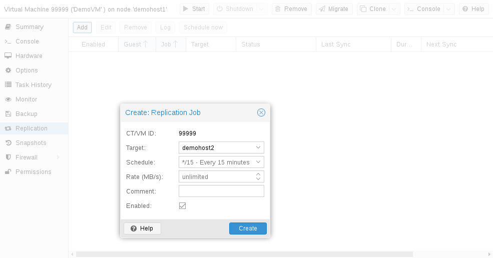
You can use the web GUI to create, modify, and remove replication jobs easily. Additionally, the command-line interface (CLI) tool pvesr can be used to do this.
You can find the replication panel on all levels (datacenter, node, virtual guest) in the web GUI. They differ in which jobs get shown: all, node- or guest-specific jobs.
When adding a new job, you need to specify the guest if not already selected as well as the target node. The replication schedule can be set if the default of all 15 minutes is not desired. You may impose a rate-limit on a replication job. The rate limit can help to keep the load on the storage acceptable.
A replication job is identified by a cluster-wide unique ID. This ID is composed of the VMID in addition to a job number. This ID must only be specified manually if the CLI tool is used.
9.5. Command-line Interface Examples
Create a replication job which runs every 5 minutes with a limited bandwidth of 10 Mbps (megabytes per second) for the guest with ID 100.
# pvesr create-local-job 100-0 pve1 --schedule "*/5" --rate 10
Disable an active job with ID 100-0.
# pvesr disable 100-0
Enable a deactivated job with ID 100-0.
# pvesr enable 100-0
Change the schedule interval of the job with ID 100-0 to once per hour.
# pvesr update 100-0 --schedule '*/00'
10. QEMU/KVM Virtual Machines
QEMU (short form for Quick Emulator) is an open source hypervisor that emulates a physical computer. From the perspective of the host system where QEMU is running, QEMU is a user program which has access to a number of local resources like partitions, files, network cards which are then passed to an emulated computer which sees them as if they were real devices.
A guest operating system running in the emulated computer accesses these devices, and runs as if it were running on real hardware. For instance, you can pass an ISO image as a parameter to QEMU, and the OS running in the emulated computer will see a real CD-ROM inserted into a CD drive.
QEMU can emulate a great variety of hardware from ARM to Sparc, but Proxmox VE is only concerned with 32 and 64 bits PC clone emulation, since it represents the overwhelming majority of server hardware. The emulation of PC clones is also one of the fastest due to the availability of processor extensions which greatly speed up QEMU when the emulated architecture is the same as the host architecture.
|
|
You may sometimes encounter the term KVM (Kernel-based Virtual Machine). It means that QEMU is running with the support of the virtualization processor extensions, via the Linux KVM module. In the context of Proxmox VE QEMU and KVM can be used interchangeably, as QEMU in Proxmox VE will always try to load the KVM module. |
QEMU inside Proxmox VE runs as a root process, since this is required to access block and PCI devices.
10.1. Emulated devices and paravirtualized devices
The PC hardware emulated by QEMU includes a motherboard, network controllers, SCSI, IDE and SATA controllers, serial ports (the complete list can be seen in the kvm(1) man page) all of them emulated in software. All these devices are the exact software equivalent of existing hardware devices, and if the OS running in the guest has the proper drivers it will use the devices as if it were running on real hardware. This allows QEMU to run unmodified operating systems.
This however has a performance cost, as running in software what was meant to run in hardware involves a lot of extra work for the host CPU. To mitigate this, QEMU can present to the guest operating system paravirtualized devices, where the guest OS recognizes it is running inside QEMU and cooperates with the hypervisor.
QEMU relies on the virtio virtualization standard, and is thus able to present paravirtualized virtio devices, which includes a paravirtualized generic disk controller, a paravirtualized network card, a paravirtualized serial port, a paravirtualized SCSI controller, etc …
|
|
It is highly recommended to use the virtio devices whenever you can, as
they provide a big performance improvement and are generally better maintained.
Using the virtio generic disk controller versus an emulated IDE controller will
double the sequential write throughput, as measured with bonnie++(8). Using
the virtio network interface can deliver up to three times the throughput of an
emulated Intel E1000 network card, as measured with iperf(1). [See this benchmark on the KVM wiki https://www.linux-kvm.org/page/Using_VirtIO_NIC] |
10.2. Virtual Machines Settings
Generally speaking Proxmox VE tries to choose sane defaults for virtual machines (VM). Make sure you understand the meaning of the settings you change, as it could incur a performance slowdown, or putting your data at risk.
10.2.1. General Settings
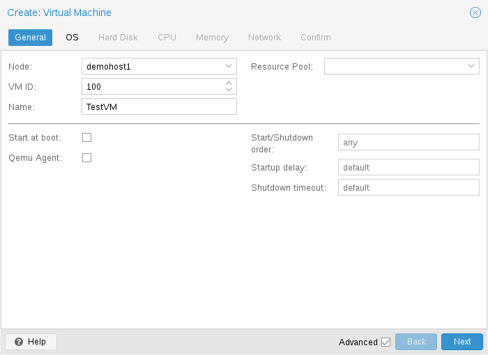
General settings of a VM include
-
the Node : the physical server on which the VM will run
-
the VM ID: a unique number in this Proxmox VE installation used to identify your VM
-
Name: a free form text string you can use to describe the VM
-
Resource Pool: a logical group of VMs
10.2.2. OS Settings
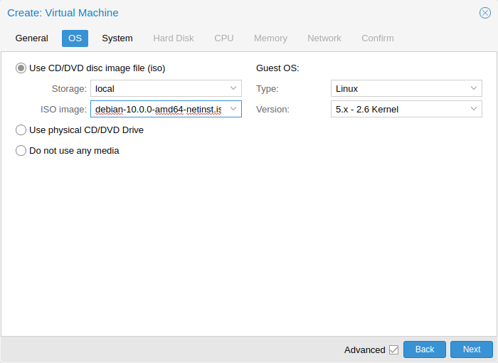
When creating a virtual machine (VM), setting the proper Operating System(OS) allows Proxmox VE to optimize some low level parameters. For instance Windows OS expect the BIOS clock to use the local time, while Unix based OS expect the BIOS clock to have the UTC time.
10.2.3. System Settings
On VM creation you can change some basic system components of the new VM. You can specify which display type you want to use.
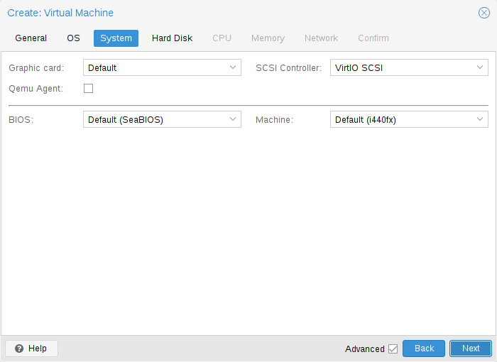
Additionally, the SCSI controller can be changed. If you plan to install the QEMU Guest Agent, or if your selected ISO image already ships and installs it automatically, you may want to tick the QEMU Agent box, which lets Proxmox VE know that it can use its features to show some more information, and complete some actions (for example, shutdown or snapshots) more intelligently.
Proxmox VE allows to boot VMs with different firmware and machine types, namely SeaBIOS and OVMF. In most cases you want to switch from the default SeaBIOS to OVMF only if you plan to use PCIe passthrough.
Machine Type
A VM’s Machine Type defines the hardware layout of the VM’s virtual motherboard. You can choose between the default Intel 440FX or the Q35 chipset, which also provides a virtual PCIe bus, and thus may be desired if you want to pass through PCIe hardware. Additionally, you can select a vIOMMU implementation.
Machine Version
Each machine type is versioned in QEMU and a given QEMU binary supports many machine versions. New versions might bring support for new features, fixes or general improvements. However, they also change properties of the virtual hardware. To avoid sudden changes from the guest’s perspective and ensure compatibility of the VM state, live-migration and snapshots with RAM will keep using the same machine version in the new QEMU instance.
For Windows guests, the machine version is pinned during creation, because Windows is sensitive to changes in the virtual hardware - even between cold boots. For example, the enumeration of network devices might be different with different machine versions. Other OSes like Linux can usually deal with such changes just fine. For those, the Latest machine version is used by default. This means that after a fresh start, the newest machine version supported by the QEMU binary is used (e.g. the newest machine version QEMU 8.1 supports is version 8.1 for each machine type).
Update to a Newer Machine Version
Very old machine versions might become deprecated in QEMU. For example, this is the case for versions 1.4 to 1.7 for the i440fx machine type. It is expected that support for these machine versions will be dropped at some point. If you see a deprecation warning, you should change the machine version to a newer one. Be sure to have a working backup first and be prepared for changes to how the guest sees hardware. In some scenarios, re-installing certain drivers might be required. You should also check for snapshots with RAM that were taken with these machine versions (i.e. the runningmachine configuration entry). Unfortunately, there is no way to change the machine version of a snapshot, so you’d need to load the snapshot to salvage any data from it.
10.2.4. Hard Disk
Bus/Controller
QEMU can emulate a number of storage controllers:
|
|
It is highly recommended to use the VirtIO SCSI or VirtIO Block controller for performance reasons and because they are better maintained. |
-
the IDE controller, has a design which goes back to the 1984 PC/AT disk controller. Even if this controller has been superseded by recent designs, each and every OS you can think of has support for it, making it a great choice if you want to run an OS released before 2003. You can connect up to 4 devices on this controller.
-
the SATA (Serial ATA) controller, dating from 2003, has a more modern design, allowing higher throughput and a greater number of devices to be connected. You can connect up to 6 devices on this controller.
-
the SCSI controller, designed in 1985, is commonly found on server grade hardware, and can connect up to 14 storage devices. Proxmox VE emulates by default a LSI 53C895A controller.
A SCSI controller of type VirtIO SCSI single and enabling the IO Thread setting for the attached disks is recommended if you aim for performance. This is the default for newly created Linux VMs since Proxmox VE 7.3. Each disk will have its own VirtIO SCSI controller, and QEMU will handle the disks IO in a dedicated thread. Linux distributions have support for this controller since 2012, and FreeBSD since 2014. For Windows OSes, you need to provide an extra ISO containing the drivers during the installation.
-
The VirtIO Block controller, often just called VirtIO or virtio-blk, is an older type of paravirtualized controller. It has been superseded by the VirtIO SCSI Controller, in terms of features.
Image Format
On each controller you attach a number of emulated hard disks, which are backed by a file or a block device residing in the configured storage. The choice of a storage type will determine the format of the hard disk image. Storages which present block devices (LVM, ZFS, Ceph) will require the raw disk image format, whereas files based storages (Ext4, NFS, CIFS, GlusterFS) will let you to choose either the raw disk image format or the QEMU image format.
-
the QEMU image format is a copy on write format which allows snapshots, and thin provisioning of the disk image.
-
the raw disk image is a bit-to-bit image of a hard disk, similar to what you would get when executing the dd command on a block device in Linux. This format does not support thin provisioning or snapshots by itself, requiring cooperation from the storage layer for these tasks. It may, however, be up to 10% faster than the QEMU image format.
[See this benchmark for details https://events.static.linuxfound.org/sites/events/files/slides/CloudOpen2013_Khoa_Huynh_v3.pdf]
-
the VMware image format only makes sense if you intend to import/export the disk image to other hypervisors.
Cache Mode
Setting the Cache mode of the hard drive will impact how the host system will notify the guest systems of block write completions. The No cache default means that the guest system will be notified that a write is complete when each block reaches the physical storage write queue, ignoring the host page cache. This provides a good balance between safety and speed.
If you want the Proxmox VE backup manager to skip a disk when doing a backup of a VM, you can set the No backup option on that disk.
If you want the Proxmox VE storage replication mechanism to skip a disk when starting a replication job, you can set the Skip replication option on that disk. As of Proxmox VE 5.0, replication requires the disk images to be on a storage of type zfspool, so adding a disk image to other storages when the VM has replication configured requires to skip replication for this disk image.
Trim/Discard
If your storage supports thin provisioning (see the storage chapter in the
Proxmox VE guide), you can activate the Discard option on a drive. With Discard
set and a TRIM-enabled guest OS
[TRIM, UNMAP, and discard
https://en.wikipedia.org/wiki/Trim_%28computing%29]
, when the VM’s filesystem
marks blocks as unused after deleting files, the controller will relay this
information to the storage, which will then shrink the disk image accordingly.
For the guest to be able to issue TRIM commands, you must enable the Discard
option on the drive. Some guest operating systems may also require the
SSD Emulation flag to be set. Note that Discard on VirtIO Block drives is
only supported on guests using Linux Kernel 5.0 or higher.
If you would like a drive to be presented to the guest as a solid-state drive rather than a rotational hard disk, you can set the SSD emulation option on that drive. There is no requirement that the underlying storage actually be backed by SSDs; this feature can be used with physical media of any type. Note that SSD emulation is not supported on VirtIO Block drives.
IO Thread
The option IO Thread can only be used when using a disk with the VirtIO controller, or with the SCSI controller, when the emulated controller type is VirtIO SCSI single. With IO Thread enabled, QEMU creates one I/O thread per storage controller rather than handling all I/O in the main event loop or vCPU threads. One benefit is better work distribution and utilization of the underlying storage. Another benefit is reduced latency (hangs) in the guest for very I/O-intensive host workloads, since neither the main thread nor a vCPU thread can be blocked by disk I/O.
10.2.5. CPU
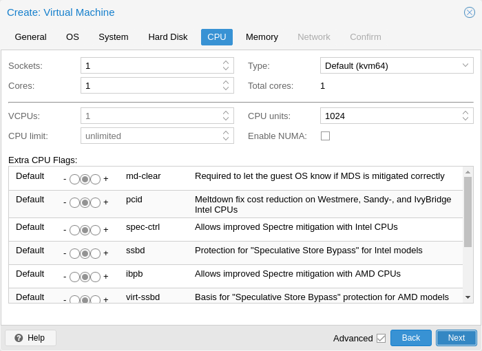
A CPU socket is a physical slot on a PC motherboard where you can plug a CPU. This CPU can then contain one or many cores, which are independent processing units. Whether you have a single CPU socket with 4 cores, or two CPU sockets with two cores is mostly irrelevant from a performance point of view. However some software licenses depend on the number of sockets a machine has, in that case it makes sense to set the number of sockets to what the license allows you.
Increasing the number of virtual CPUs (cores and sockets) will usually provide a performance improvement though that is heavily dependent on the use of the VM. Multi-threaded applications will of course benefit from a large number of virtual CPUs, as for each virtual cpu you add, QEMU will create a new thread of execution on the host system. If you’re not sure about the workload of your VM, it is usually a safe bet to set the number of Total cores to 2.
|
|
It is perfectly safe if the overall number of cores of all your VMs is greater than the number of cores on the server (for example, 4 VMs each with 4 cores (= total 16) on a machine with only 8 cores). In that case the host system will balance the QEMU execution threads between your server cores, just like if you were running a standard multi-threaded application. However, Proxmox VE will prevent you from starting VMs with more virtual CPU cores than physically available, as this will only bring the performance down due to the cost of context switches. |
Resource Limits
cpulimit
In addition to the number of virtual cores, the total available “Host CPU Time” for the VM can be set with the cpulimit option. It is a floating point value representing CPU time in percent, so 1.0 is equal to 100%, 2.5 to 250% and so on. If a single process would fully use one single core it would have 100% CPU Time usage. If a VM with four cores utilizes all its cores fully it would theoretically use 400%. In reality the usage may be even a bit higher as QEMU can have additional threads for VM peripherals besides the vCPU core ones.
This setting can be useful when a VM should have multiple vCPUs because it is running some processes in parallel, but the VM as a whole should not be able to run all vCPUs at 100% at the same time.
For example, suppose you have a virtual machine that would benefit from having 8 virtual CPUs, but you don’t want the VM to be able to max out all 8 cores running at full load - because that would overload the server and leave other virtual machines and containers with too little CPU time. To solve this, you could set cpulimit to 4.0 (=400%). This means that if the VM fully utilizes all 8 virtual CPUs by running 8 processes simultaneously, each vCPU will receive a maximum of 50% CPU time from the physical cores. However, if the VM workload only fully utilizes 4 virtual CPUs, it could still receive up to 100% CPU time from a physical core, for a total of 400%.
|
|
VMs can, depending on their configuration, use additional threads, such as for networking or IO operations but also live migration. Thus a VM can show up to use more CPU time than just its virtual CPUs could use. To ensure that a VM never uses more CPU time than vCPUs assigned, set the cpulimit to the same value as the total core count. |
cpuuntis
With the cpuunits option, nowadays often called CPU shares or CPU weight, you can control how much CPU time a VM gets compared to other running VMs. It is a relative weight which defaults to 100 (or 1024 if the host uses legacy cgroup v1). If you increase this for a VM it will be prioritized by the scheduler in comparison to other VMs with lower weight.
For example, if VM 100 has set the default 100 and VM 200 was changed to 200, the latter VM 200 would receive twice the CPU bandwidth than the first VM 100.
For more information see man systemd.resource-control, here CPUQuota corresponds to cpulimit and CPUWeight to our cpuunits setting. Visit its Notes section for references and implementation details.
affinity
With the affinity option, you can specify the physical CPU cores that are used to run the VM’s vCPUs. Peripheral VM processes, such as those for I/O, are not affected by this setting. Note that the CPU affinity is not a security feature.
Forcing a CPU affinity can make sense in certain cases but is accompanied by an increase in complexity and maintenance effort. For example, if you want to add more VMs later or migrate VMs to nodes with fewer CPU cores. It can also easily lead to asynchronous and therefore limited system performance if some CPUs are fully utilized while others are almost idle.
The affinity is set through the taskset CLI tool. It accepts the host CPU numbers (see lscpu) in the List Format from man cpuset. This ASCII decimal list can contain numbers but also number ranges. For example, the affinity 0-1,8-11 (expanded 0, 1, 8, 9, 10, 11) would allow the VM to run on only these six specific host cores.
CPU Type
QEMU can emulate a number different of CPU types from 486 to the latest Xeon processors. Each new processor generation adds new features, like hardware assisted 3d rendering, random number generation, memory protection, etc. Also, a current generation can be upgraded through microcode update with bug or security fixes.
Usually you should select for your VM a processor type which closely matches the CPU of the host system, as it means that the host CPU features (also called CPU flags ) will be available in your VMs. If you want an exact match, you can set the CPU type to host in which case the VM will have exactly the same CPU flags as your host system.
This has a downside though. If you want to do a live migration of VMs between different hosts, your VM might end up on a new system with a different CPU type or a different microcode version. If the CPU flags passed to the guest are missing, the QEMU process will stop. To remedy this QEMU has also its own virtual CPU types, that Proxmox VE uses by default.
The backend default is kvm64 which works on essentially all x86_64 host CPUs and the UI default when creating a new VM is x86-64-v2-AES, which requires a host CPU starting from Westmere for Intel or at least a fourth generation Opteron for AMD.
In short:
If you don’t care about live migration or have a homogeneous cluster where all nodes have the same CPU and same microcode version, set the CPU type to host, as in theory this will give your guests maximum performance.
If you care about live migration and security, and you have only Intel CPUs or only AMD CPUs, choose the lowest generation CPU model of your cluster.
If you care about live migration without security, or have mixed Intel/AMD cluster, choose the lowest compatible virtual QEMU CPU type.
|
|
Live migrations between Intel and AMD host CPUs have no guarantee to work. |
QEMU CPU Types
QEMU also provide virtual CPU types, compatible with both Intel and AMD host CPUs.
|
|
To mitigate the Spectre vulnerability for virtual CPU types, you need to add the relevant CPU flags, see Meltdown / Spectre related CPU flags. |
Historically, Proxmox VE had the kvm64 CPU model, with CPU flags at the level of Pentium 4 enabled, so performance was not great for certain workloads.
In the summer of 2020, AMD, Intel, Red Hat, and SUSE collaborated to define three x86-64 microarchitecture levels on top of the x86-64 baseline, with modern flags enabled. For details, see the x86-64-ABI specification.
|
|
Some newer distributions like CentOS 9 are now built with x86-64-v2 flags as a minimum requirement. |
-
kvm64 (x86-64-v1): Compatible with Intel CPU >= Pentium 4, AMD CPU >= Phenom.
-
x86-64-v2: Compatible with Intel CPU >= Nehalem, AMD CPU >= Opteron_G3. Added CPU flags compared to x86-64-v1: +cx16, +lahf-lm, +popcnt, +pni, +sse4.1, +sse4.2, +ssse3.
-
x86-64-v2-AES: Compatible with Intel CPU >= Westmere, AMD CPU >= Opteron_G4. Added CPU flags compared to x86-64-v2: +aes.
-
x86-64-v3: Compatible with Intel CPU >= Broadwell, AMD CPU >= EPYC. Added CPU flags compared to x86-64-v2-AES: +avx, +avx2, +bmi1, +bmi2, +f16c, +fma, +movbe, +xsave.
-
x86-64-v4: Compatible with Intel CPU >= Skylake, AMD CPU >= EPYC v4 Genoa. Added CPU flags compared to x86-64-v3: +avx512f, +avx512bw, +avx512cd, +avx512dq, +avx512vl.
Custom CPU Types
You can specify custom CPU types with a configurable set of features. These are maintained in the configuration file /etc/pve/virtual-guest/cpu-models.conf by an administrator. See man cpu-models.conf for format details.
Specified custom types can be selected by any user with the Sys.Audit privilege on /nodes. When configuring a custom CPU type for a VM via the CLI or API, the name needs to be prefixed with custom-.
Meltdown / Spectre related CPU flags
There are several CPU flags related to the Meltdown and Spectre vulnerabilities
[Meltdown Attack https://meltdownattack.com/]
which need to be set
manually unless the selected CPU type of your VM already enables them by default.
There are two requirements that need to be fulfilled in order to use these CPU flags:
-
The host CPU(s) must support the feature and propagate it to the guest’s virtual CPU(s)
-
The guest operating system must be updated to a version which mitigates the attacks and is able to utilize the CPU feature
Otherwise you need to set the desired CPU flag of the virtual CPU, either by editing the CPU options in the web UI, or by setting the flags property of the cpu option in the VM configuration file.
For Spectre v1,v2,v4 fixes, your CPU or system vendor also needs to provide a so-called “microcode update” for your CPU, see chapter Firmware Updates. Note that not all affected CPUs can be updated to support spec-ctrl.
To check if the Proxmox VE host is vulnerable, execute the following command as root:
for f in /sys/devices/system/cpu/vulnerabilities/*; do echo "${f##*/} -" $(cat "$f"); done
A community script is also available to detect if the host is still vulnerable.
[spectre-meltdown-checker https://meltdown.ovh/]
Intel processors
-
pcid
This reduces the performance impact of the Meltdown (CVE-2017-5754) mitigation called Kernel Page-Table Isolation (KPTI), which effectively hides the Kernel memory from the user space. Without PCID, KPTI is quite an expensive mechanism
[PCID is now a critical performance/security feature on x86 https://groups.google.com/forum/m/#!topic/mechanical-sympathy/L9mHTbeQLNU]
.To check if the Proxmox VE host supports PCID, execute the following command as root:
# grep ' pcid ' /proc/cpuinfo
If this does not return empty your host’s CPU has support for pcid.
-
spec-ctrl
Required to enable the Spectre v1 (CVE-2017-5753) and Spectre v2 (CVE-2017-5715) fix, in cases where retpolines are not sufficient. Included by default in Intel CPU models with -IBRS suffix. Must be explicitly turned on for Intel CPU models without -IBRS suffix. Requires an updated host CPU microcode (intel-microcode >= 20180425).
-
ssbd
Required to enable the Spectre V4 (CVE-2018-3639) fix. Not included by default in any Intel CPU model. Must be explicitly turned on for all Intel CPU models. Requires an updated host CPU microcode(intel-microcode >= 20180703).
AMD processors
-
ibpb
Required to enable the Spectre v1 (CVE-2017-5753) and Spectre v2 (CVE-2017-5715) fix, in cases where retpolines are not sufficient. Included by default in AMD CPU models with -IBPB suffix. Must be explicitly turned on for AMD CPU models without -IBPB suffix. Requires the host CPU microcode to support this feature before it can be used for guest CPUs.
-
virt-ssbd
Required to enable the Spectre v4 (CVE-2018-3639) fix. Not included by default in any AMD CPU model. Must be explicitly turned on for all AMD CPU models. This should be provided to guests, even if amd-ssbd is also provided, for maximum guest compatibility. Note that this must be explicitly enabled when when using the "host" cpu model, because this is a virtual feature which does not exist in the physical CPUs.
-
amd-ssbd
Required to enable the Spectre v4 (CVE-2018-3639) fix. Not included by default in any AMD CPU model. Must be explicitly turned on for all AMD CPU models. This provides higher performance than virt-ssbd, therefore a host supporting this should always expose this to guests if possible. virt-ssbd should none the less also be exposed for maximum guest compatibility as some kernels only know about virt-ssbd.
-
amd-no-ssb
Recommended to indicate the host is not vulnerable to Spectre V4 (CVE-2018-3639). Not included by default in any AMD CPU model. Future hardware generations of CPU will not be vulnerable to CVE-2018-3639, and thus the guest should be told not to enable its mitigations, by exposing amd-no-ssb. This is mutually exclusive with virt-ssbd and amd-ssbd.
NUMA
You can also optionally emulate a NUMA
[https://en.wikipedia.org/wiki/Non-uniform_memory_access]
architecture
in your VMs. The basics of the NUMA architecture mean that instead of having a
global memory pool available to all your cores, the memory is spread into local
banks close to each socket.
This can bring speed improvements as the memory bus is not a bottleneck
anymore. If your system has a NUMA architecture
[if the command
numactl --hardware | grep available returns more than one node, then your host
system has a NUMA architecture]
we recommend to activate the option, as this
will allow proper distribution of the VM resources on the host system.
This option is also required to hot-plug cores or RAM in a VM.
If the NUMA option is used, it is recommended to set the number of sockets to the number of nodes of the host system.
vCPU hot-plug
Modern operating systems introduced the capability to hot-plug and, to a certain extent, hot-unplug CPUs in a running system. Virtualization allows us to avoid a lot of the (physical) problems real hardware can cause in such scenarios. Still, this is a rather new and complicated feature, so its use should be restricted to cases where its absolutely needed. Most of the functionality can be replicated with other, well tested and less complicated, features, see Resource Limits.
In Proxmox VE the maximal number of plugged CPUs is always cores * sockets. To start a VM with less than this total core count of CPUs you may use the vcpus setting, it denotes how many vCPUs should be plugged in at VM start.
Currently only this feature is only supported on Linux, a kernel newer than 3.10 is needed, a kernel newer than 4.7 is recommended.
You can use a udev rule as follow to automatically set new CPUs as online in the guest:
SUBSYSTEM=="cpu", ACTION=="add", TEST=="online", ATTR{online}=="0", ATTR{online}="1"
Save this under /etc/udev/rules.d/ as a file ending in .rules.
Note: CPU hot-remove is machine dependent and requires guest cooperation. The deletion command does not guarantee CPU removal to actually happen, typically it’s a request forwarded to guest OS using target dependent mechanism, such as ACPI on x86/amd64.
10.2.6. Memory
For each VM you have the option to set a fixed size memory or asking Proxmox VE to dynamically allocate memory based on the current RAM usage of the host.
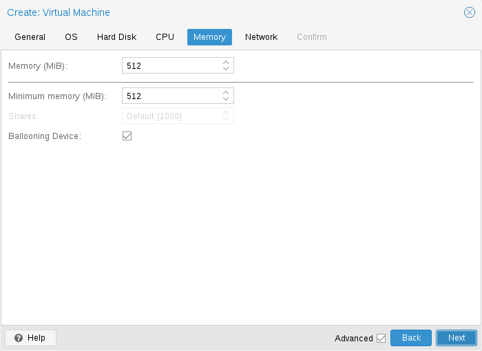
When setting memory and minimum memory to the same amount Proxmox VE will simply allocate what you specify to your VM.
Even when using a fixed memory size, the ballooning device gets added to the VM, because it delivers useful information such as how much memory the guest really uses. In general, you should leave ballooning enabled, but if you want to disable it (like for debugging purposes), simply uncheck Ballooning Device or set
balloon: 0
in the configuration.
When setting the minimum memory lower than memory, Proxmox VE will make sure that the minimum amount you specified is always available to the VM, and if RAM usage on the host is below 80%, will dynamically add memory to the guest up to the maximum memory specified.
When the host is running low on RAM, the VM will then release some memory
back to the host, swapping running processes if needed and starting the oom
killer in last resort. The passing around of memory between host and guest is
done via a special balloon kernel driver running inside the guest, which will
grab or release memory pages from the host.
[A good explanation of the inner workings of the balloon driver can be found here https://rwmj.wordpress.com/2010/07/17/virtio-balloon/]
When multiple VMs use the autoallocate facility, it is possible to set a
Shares coefficient which indicates the relative amount of the free host memory
that each VM should take. Suppose for instance you have four VMs, three of them
running an HTTP server and the last one is a database server. To cache more
database blocks in the database server RAM, you would like to prioritize the
database VM when spare RAM is available. For this you assign a Shares property
of 3000 to the database VM, leaving the other VMs to the Shares default setting
of 1000. The host server has 32GB of RAM, and is currently using 16GB, leaving 32
* 80/100 - 16 = 9GB RAM to be allocated to the VMs on top of their configured
minimum memory amount. The database VM will benefit from 9 * 3000 / (3000
1000 + 1000 + 1000) = 4.5 GB extra RAM and each HTTP server from 1.5 GB.
All Linux distributions released after 2010 have the balloon kernel driver included. For Windows OSes, the balloon driver needs to be added manually and can incur a slowdown of the guest, so we don’t recommend using it on critical systems.
When allocating RAM to your VMs, a good rule of thumb is always to leave 1GB of RAM available to the host.
10.2.7. Network Device
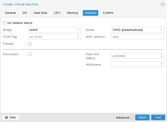
Each VM can have many Network interface controllers (NIC), of four different types:
-
Intel E1000 is the default, and emulates an Intel Gigabit network card.
-
the VirtIO paravirtualized NIC should be used if you aim for maximum performance. Like all VirtIO devices, the guest OS should have the proper driver installed.
-
the Realtek 8139 emulates an older 100 MB/s network card, and should only be used when emulating older operating systems ( released before 2002 )
-
the vmxnet3 is another paravirtualized device, which should only be used when importing a VM from another hypervisor.
Proxmox VE will generate for each NIC a random MAC address, so that your VM is addressable on Ethernet networks.
The NIC you added to the VM can follow one of two different models:
-
in the default Bridged mode each virtual NIC is backed on the host by a tap device, ( a software loopback device simulating an Ethernet NIC ). This tap device is added to a bridge, by default vmbr0 in Proxmox VE. In this mode, VMs have direct access to the Ethernet LAN on which the host is located.
-
in the alternative NAT mode, each virtual NIC will only communicate with the QEMU user networking stack, where a built-in router and DHCP server can provide network access. This built-in DHCP will serve addresses in the private 10.0.2.0/24 range. The NAT mode is much slower than the bridged mode, and should only be used for testing. This mode is only available via CLI or the API, but not via the web UI.
You can also skip adding a network device when creating a VM by selecting No network device.
You can overwrite the MTU setting for each VM network device. The option mtu=1 represents a special case, in which the MTU value will be inherited from the underlying bridge. This option is only available for VirtIO network devices.
If you are using the VirtIO driver, you can optionally activate the Multiqueue option. This option allows the guest OS to process networking packets using multiple virtual CPUs, providing an increase in the total number of packets transferred.
When using the VirtIO driver with Proxmox VE, each NIC network queue is passed to the host kernel, where the queue will be processed by a kernel thread spawned by the vhost driver. With this option activated, it is possible to pass multiple network queues to the host kernel for each NIC.
When using Multiqueue, it is recommended to set it to a value equal to the number of vCPUs of your guest. Remember that the number of vCPUs is the number of sockets times the number of cores configured for the VM. You also need to set the number of multi-purpose channels on each VirtIO NIC in the VM with this ethtool command:
ethtool -L ens1 combined X
where X is the number of the number of vCPUs of the VM.
To configure a Windows guest for Multiqueue install the Redhat VirtIO Ethernet Adapter drivers, then adapt the NIC’s configuration as follows. Open the device manager, right click the NIC under "Network adapters", and select "Properties". Then open the "Advanced" tab and select "Receive Side Scaling" from the list on the left. Make sure it is set to "Enabled". Next, navigate to "Maximum number of RSS Queues" in the list and set it to the number of vCPUs of your VM. Once you verified that the settings are correct, click "OK" to confirm them.
You should note that setting the Multiqueue parameter to a value greater than one will increase the CPU load on the host and guest systems as the traffic increases. We recommend to set this option only when the VM has to process a great number of incoming connections, such as when the VM is running as a router, reverse proxy or a busy HTTP server doing long polling.
10.2.8. Display
QEMU can virtualize a few types of VGA hardware. Some examples are:
-
std, the default, emulates a card with Bochs VBE extensions.
-
cirrus, this was once the default, it emulates a very old hardware module with all its problems. This display type should only be used if really necessary
[https://www.kraxel.org/blog/2014/10/qemu-using-cirrus-considered-harmful/ qemu: using cirrus considered harmful]
, for example, if using Windows XP or earlier -
vmware, is a VMWare SVGA-II compatible adapter.
-
qxl, is the QXL paravirtualized graphics card. Selecting this also enables SPICE (a remote viewer protocol) for the VM.
-
virtio-gl, often named VirGL is a virtual 3D GPU for use inside VMs that can offload workloads to the host GPU without requiring special (expensive) models and drivers and neither binding the host GPU completely, allowing reuse between multiple guests and or the host.
VirGL support needs some extra libraries that aren’t installed by default due to being relatively big and also not available as open source for all GPU models/vendors. For most setups you’ll just need to do: apt install libgl1 libegl1
You can edit the amount of memory given to the virtual GPU, by setting the memory option. This can enable higher resolutions inside the VM, especially with SPICE/QXL.
As the memory is reserved by display device, selecting Multi-Monitor mode for SPICE (such as qxl2 for dual monitors) has some implications:
-
Windows needs a device for each monitor, so if your ostype is some version of Windows, Proxmox VE gives the VM an extra device per monitor. Each device gets the specified amount of memory.
-
Linux VMs, can always enable more virtual monitors, but selecting a Multi-Monitor mode multiplies the memory given to the device with the number of monitors.
Selecting serialX as display type disables the VGA output, and redirects the Web Console to the selected serial port. A configured display memory setting will be ignored in that case.
You can enable the VNC clipboard by setting clipboard to vnc.
# qm set <vmid> -vga <displaytype>,clipboard=vnc
In order to use the clipboard feature, you must first install the SPICE guest tools. On Debian-based distributions, this can be achieved by installing spice-vdagent. For other Operating Systems search for it in the offical repositories or see: https://www.spice-space.org/download.html
Once you have installed the spice guest tools, you can use the VNC clipboard function (e.g. in the noVNC console panel). However, if you’re using SPICE, virtio or virgl, you’ll need to choose which clipboard to use. This is because the default SPICE clipboard will be replaced by the VNC clipboard, if clipboard is set to vnc.
10.2.9. USB Passthrough
There are two different types of USB passthrough devices:
-
Host USB passthrough
-
SPICE USB passthrough
Host USB passthrough works by giving a VM a USB device of the host. This can either be done via the vendor- and product-id, or via the host bus and port.
The vendor/product-id looks like this: 0123:abcd, where 0123 is the id of the vendor, and abcd is the id of the product, meaning two pieces of the same usb device have the same id.
The bus/port looks like this: 1-2.3.4, where 1 is the bus and 2.3.4 is the port path. This represents the physical ports of your host (depending of the internal order of the usb controllers).
If a device is present in a VM configuration when the VM starts up, but the device is not present in the host, the VM can boot without problems. As soon as the device/port is available in the host, it gets passed through.
|
|
Using this kind of USB passthrough means that you cannot move a VM online to another host, since the hardware is only available on the host the VM is currently residing. |
The second type of passthrough is SPICE USB passthrough. If you add one or more SPICE USB ports to your VM, you can dynamically pass a local USB device from your SPICE client through to the VM. This can be useful to redirect an input device or hardware dongle temporarily.
It is also possible to map devices on a cluster level, so that they can be properly used with HA and hardware changes are detected and non root users can configure them. See Resource Mapping for details on that.
10.2.10. BIOS and UEFI
In order to properly emulate a computer, QEMU needs to use a firmware. Which, on common PCs often known as BIOS or (U)EFI, is executed as one of the first steps when booting a VM. It is responsible for doing basic hardware initialization and for providing an interface to the firmware and hardware for the operating system. By default QEMU uses SeaBIOS for this, which is an open-source, x86 BIOS implementation. SeaBIOS is a good choice for most standard setups.
Some operating systems (such as Windows 11) may require use of an UEFI
compatible implementation. In such cases, you must use OVMF instead,
which is an open-source UEFI implementation.
[See the OVMF Project https://github.com/tianocore/tianocore.github.io/wiki/OVMF]
There are other scenarios in which the SeaBIOS may not be the ideal firmware to
boot from, for example if you want to do VGA passthrough.
[Alex
Williamson has a good blog entry about this
https://vfio.blogspot.co.at/2014/08/primary-graphics-assignment-without-vga.html]
If you want to use OVMF, there are several things to consider:
In order to save things like the boot order, there needs to be an EFI Disk. This disk will be included in backups and snapshots, and there can only be one.
You can create such a disk with the following command:
# qm set <vmid> -efidisk0 <storage>:1,format=<format>,efitype=4m,pre-enrolled-keys=1
Where <storage> is the storage where you want to have the disk, and <format> is a format which the storage supports. Alternatively, you can create such a disk through the web interface with Add → EFI Disk in the hardware section of a VM.
The efitype option specifies which version of the OVMF firmware should be used. For new VMs, this should always be 4m, as it supports Secure Boot and has more space allocated to support future development (this is the default in the GUI).
pre-enroll-keys specifies if the efidisk should come pre-loaded with distribution-specific and Microsoft Standard Secure Boot keys. It also enables Secure Boot by default (though it can still be disabled in the OVMF menu within the VM).
|
|
If you want to start using Secure Boot in an existing VM (that still uses a 2m efidisk), you need to recreate the efidisk. To do so, delete the old one (qm set <vmid> -delete efidisk0) and add a new one as described above. This will reset any custom configurations you have made in the OVMF menu! |
When using OVMF with a virtual display (without VGA passthrough), you need to set the client resolution in the OVMF menu (which you can reach with a press of the ESC button during boot), or you have to choose SPICE as the display type.
10.2.11. Trusted Platform Module (TPM)
A Trusted Platform Module is a device which stores secret data - such as encryption keys - securely and provides tamper-resistance functions for validating system boot.
Certain operating systems (such as Windows 11) require such a device to be attached to a machine (be it physical or virtual).
A TPM is added by specifying a tpmstate volume. This works similar to an efidisk, in that it cannot be changed (only removed) once created. You can add one via the following command:
# qm set <vmid> -tpmstate0 <storage>:1,version=<version>
Where <storage> is the storage you want to put the state on, and <version> is either v1.2 or v2.0. You can also add one via the web interface, by choosing Add → TPM State in the hardware section of a VM.
The v2.0 TPM spec is newer and better supported, so unless you have a specific implementation that requires a v1.2 TPM, it should be preferred.
|
|
Compared to a physical TPM, an emulated one does not provide any real security benefits. The point of a TPM is that the data on it cannot be modified easily, except via commands specified as part of the TPM spec. Since with an emulated device the data storage happens on a regular volume, it can potentially be edited by anyone with access to it. |
10.2.12. Inter-VM shared memory
You can add an Inter-VM shared memory device (ivshmem), which allows one to share memory between the host and a guest, or also between multiple guests.
To add such a device, you can use qm:
# qm set <vmid> -ivshmem size=32,name=foo
Where the size is in MiB. The file will be located under /dev/shm/pve-shm-$name (the default name is the vmid).
|
|
Currently the device will get deleted as soon as any VM using it got shutdown or stopped. Open connections will still persist, but new connections to the exact same device cannot be made anymore. |
A use case for such a device is the Looking Glass
[Looking Glass: https://looking-glass.io/]
project, which enables high
performance, low-latency display mirroring between host and guest.
10.2.13. Audio Device
To add an audio device run the following command:
qm set <vmid> -audio0 device=<device>
Supported audio devices are:
-
ich9-intel-hda: Intel HD Audio Controller, emulates ICH9
-
intel-hda: Intel HD Audio Controller, emulates ICH6
-
AC97: Audio Codec '97, useful for older operating systems like Windows XP
There are two backends available:
-
spice
-
none
The spice backend can be used in combination with SPICE while the none backend can be useful if an audio device is needed in the VM for some software to work. To use the physical audio device of the host use device passthrough (see PCI Passthrough and USB Passthrough). Remote protocols like Microsoft’s RDP have options to play sound.
10.2.14. VirtIO RNG
A RNG (Random Number Generator) is a device providing entropy (randomness) to a system. A virtual hardware-RNG can be used to provide such entropy from the host system to a guest VM. This helps to avoid entropy starvation problems in the guest (a situation where not enough entropy is available and the system may slow down or run into problems), especially during the guests boot process.
To add a VirtIO-based emulated RNG, run the following command:
qm set <vmid> -rng0 source=<source>[,max_bytes=X,period=Y]
source specifies where entropy is read from on the host and has to be one of the following:
-
/dev/urandom: Non-blocking kernel entropy pool (preferred)
-
/dev/random: Blocking kernel pool (not recommended, can lead to entropy starvation on the host system)
-
/dev/hwrng: To pass through a hardware RNG attached to the host (if multiple are available, the one selected in /sys/devices/virtual/misc/hw_random/rng_current will be used)
A limit can be specified via the max_bytes and period parameters, they are read as max_bytes per period in milliseconds. However, it does not represent a linear relationship: 1024B/1000ms would mean that up to 1 KiB of data becomes available on a 1 second timer, not that 1 KiB is streamed to the guest over the course of one second. Reducing the period can thus be used to inject entropy into the guest at a faster rate.
By default, the limit is set to 1024 bytes per 1000 ms (1 KiB/s). It is recommended to always use a limiter to avoid guests using too many host resources. If desired, a value of 0 for max_bytes can be used to disable all limits.
10.2.15. Device Boot Order
QEMU can tell the guest which devices it should boot from, and in which order. This can be specified in the config via the boot property, for example:
boot: order=scsi0;net0;hostpci0
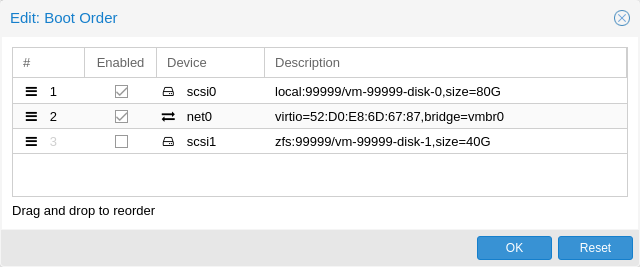
This way, the guest would first attempt to boot from the disk scsi0, if that fails, it would go on to attempt network boot from net0, and in case that fails too, finally attempt to boot from a passed through PCIe device (seen as disk in case of NVMe, otherwise tries to launch into an option ROM).
On the GUI you can use a drag-and-drop editor to specify the boot order, and use the checkbox to enable or disable certain devices for booting altogether.
|
|
If your guest uses multiple disks to boot the OS or load the bootloader, all of them must be marked as bootable (that is, they must have the checkbox enabled or appear in the list in the config) for the guest to be able to boot. This is because recent SeaBIOS and OVMF versions only initialize disks if they are marked bootable. |
In any case, even devices not appearing in the list or having the checkmark disabled will still be available to the guest, once it’s operating system has booted and initialized them. The bootable flag only affects the guest BIOS and bootloader.
10.2.16. Automatic Start and Shutdown of Virtual Machines
After creating your VMs, you probably want them to start automatically when the host system boots. For this you need to select the option Start at boot from the Options Tab of your VM in the web interface, or set it with the following command:
# qm set <vmid> -onboot 1
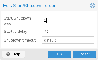
In some case you want to be able to fine tune the boot order of your VMs, for instance if one of your VM is providing firewalling or DHCP to other guest systems. For this you can use the following parameters:
-
Start/Shutdown order: Defines the start order priority. For example, set it to 1 if you want the VM to be the first to be started. (We use the reverse startup order for shutdown, so a machine with a start order of 1 would be the last to be shut down). If multiple VMs have the same order defined on a host, they will additionally be ordered by VMID in ascending order.
-
Startup delay: Defines the interval between this VM start and subsequent VMs starts. For example, set it to 240 if you want to wait 240 seconds before starting other VMs.
-
Shutdown timeout: Defines the duration in seconds Proxmox VE should wait for the VM to be offline after issuing a shutdown command. By default this value is set to 180, which means that Proxmox VE will issue a shutdown request and wait 180 seconds for the machine to be offline. If the machine is still online after the timeout it will be stopped forcefully.
|
|
VMs managed by the HA stack do not follow the start on boot and boot order options currently. Those VMs will be skipped by the startup and shutdown algorithm as the HA manager itself ensures that VMs get started and stopped. |
Please note that machines without a Start/Shutdown order parameter will always start after those where the parameter is set. Further, this parameter can only be enforced between virtual machines running on the same host, not cluster-wide.
If you require a delay between the host boot and the booting of the first VM, see the section on Proxmox VE Node Management.
10.2.17. QEMU Guest Agent
The QEMU Guest Agent is a service which runs inside the VM, providing a communication channel between the host and the guest. It is used to exchange information and allows the host to issue commands to the guest.
For example, the IP addresses in the VM summary panel are fetched via the guest agent.
Or when starting a backup, the guest is told via the guest agent to sync outstanding writes via the fs-freeze and fs-thaw commands.
For the guest agent to work properly the following steps must be taken:
-
install the agent in the guest and make sure it is running
-
enable the communication via the agent in Proxmox VE
Install Guest Agent
For most Linux distributions, the guest agent is available. The package is usually named qemu-guest-agent.
For Windows, it can be installed from the Fedora VirtIO driver ISO.
Enable Guest Agent Communication
Communication from Proxmox VE with the guest agent can be enabled in the VM’s Options panel. A fresh start of the VM is necessary for the changes to take effect.
Automatic TRIM Using QGA
It is possible to enable the Run guest-trim option. With this enabled, Proxmox VE will issue a trim command to the guest after the following operations that have the potential to write out zeros to the storage:
-
moving a disk to another storage
-
live migrating a VM to another node with local storage
On a thin provisioned storage, this can help to free up unused space.
|
|
There is a caveat with ext4 on Linux, because it uses an in-memory optimization to avoid issuing duplicate TRIM requests. Since the guest doesn’t know about the change in the underlying storage, only the first guest-trim will run as expected. Subsequent ones, until the next reboot, will only consider parts of the filesystem that changed since then. |
Filesystem Freeze & Thaw on Backup
By default, guest filesystems are synced via the fs-freeze QEMU Guest Agent Command when a backup is performed, to provide consistency.
On Windows guests, some applications might handle consistent backups themselves by hooking into the Windows VSS (Volume Shadow Copy Service) layer, a fs-freeze then might interfere with that. For example, it has been observed that calling fs-freeze with some SQL Servers triggers VSS to call the SQL Writer VSS module in a mode that breaks the SQL Server backup chain for differential backups.
For such setups you can configure Proxmox VE to not issue a freeze-and-thaw cycle on backup by setting the freeze-fs-on-backup QGA option to 0. This can also be done via the GUI with the Freeze/thaw guest filesystems on backup for consistency option.
|
|
Disabling this option can potentially lead to backups with inconsistent filesystems and should therefore only be disabled if you know what you are doing. |
Troubleshooting
Make sure the guest agent is installed and running.
Once the guest agent is enabled, Proxmox VE will send power commands like shutdown via the guest agent. If the guest agent is not running, commands cannot get executed properly and the shutdown command will run into a timeout.
10.2.18. SPICE Enhancements
SPICE Enhancements are optional features that can improve the remote viewer experience.
To enable them via the GUI go to the Options panel of the virtual machine. Run the following command to enable them via the CLI:
qm set <vmid> -spice_enhancements foldersharing=1,videostreaming=all
|
|
To use these features the Display of the virtual machine must be set to SPICE (qxl). |
Folder Sharing
Share a local folder with the guest. The spice-webdavd daemon needs to be installed in the guest. It makes the shared folder available through a local WebDAV server located at http://localhost:9843.
For Windows guests the installer for the Spice WebDAV daemon can be downloaded from the official SPICE website.
Most Linux distributions have a package called spice-webdavd that can be installed.
To share a folder in Virt-Viewer (Remote Viewer) go to File → Preferences. Select the folder to share and then enable the checkbox.
|
|
Folder sharing currently only works in the Linux version of Virt-Viewer. |
|
|
Experimental! Currently this feature does not work reliably. |
Video Streaming
Fast refreshing areas are encoded into a video stream. Two options exist:
-
all: Any fast refreshing area will be encoded into a video stream.
-
filter: Additional filters are used to decide if video streaming should be used (currently only small window surfaces are skipped).
A general recommendation if video streaming should be enabled and which option to choose from cannot be given. Your mileage may vary depending on the specific circumstances.
Troubleshooting
Make sure the WebDAV service is enabled and running in the guest. On Windows it is called Spice webdav proxy. In Linux the name is spice-webdavd but can be different depending on the distribution.
If the service is running, check the WebDAV server by opening http://localhost:9843 in a browser in the guest.
It can help to restart the SPICE session.
10.3. Migration
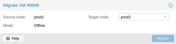
If you have a cluster, you can migrate your VM to another host with
# qm migrate <vmid> <target>
There are generally two mechanisms for this
-
Online Migration (aka Live Migration)
-
Offline Migration
10.3.1. Online Migration
If your VM is running and no locally bound resources are configured (such as devices that are passed through), you can initiate a live migration with the --online flag in the qm migration command evocation. The web interface defaults to live migration when the VM is running.
How it works
Online migration first starts a new QEMU process on the target host with the incoming flag, which performs only basic initialization with the guest vCPUs still paused and then waits for the guest memory and device state data streams of the source Virtual Machine. All other resources, such as disks, are either shared or got already sent before runtime state migration of the VMs begins; so only the memory content and device state remain to be transferred.
Once this connection is established, the source begins asynchronously sending the memory content to the target. If the guest memory on the source changes, those sections are marked dirty and another pass is made to send the guest memory data. This loop is repeated until the data difference between running source VM and incoming target VM is small enough to be sent in a few milliseconds, because then the source VM can be paused completely, without a user or program noticing the pause, so that the remaining data can be sent to the target, and then unpause the targets VM’s CPU to make it the new running VM in well under a second.
Requirements
For Live Migration to work, there are some things required:
-
The VM has no local resources that cannot be migrated. For example, PCI or USB devices that are passed through currently block live-migration. Local Disks, on the other hand, can be migrated by sending them to the target just fine.
-
The hosts are located in the same Proxmox VE cluster.
-
The hosts have a working (and reliable) network connection between them.
-
The target host must have the same, or higher versions of the Proxmox VE packages. Although it can sometimes work the other way around, this cannot be guaranteed.
-
The hosts have CPUs from the same vendor with similar capabilities. Different vendor might work depending on the actual models and VMs CPU type configured, but it cannot be guaranteed - so please test before deploying such a setup in production.
10.3.2. Offline Migration
If you have local resources, you can still migrate your VMs offline as long as all disk are on storage defined on both hosts. Migration then copies the disks to the target host over the network, as with online migration. Note that any hardware passthrough configuration may need to be adapted to the device location on the target host.
10.4. Copies and Clones
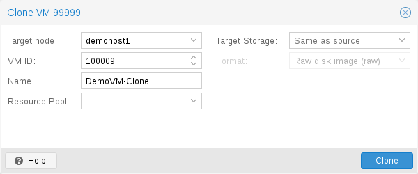
VM installation is usually done using an installation media (CD-ROM) from the operating system vendor. Depending on the OS, this can be a time consuming task one might want to avoid.
An easy way to deploy many VMs of the same type is to copy an existing VM. We use the term clone for such copies, and distinguish between linked and full clones.
- Full Clone
-
The result of such copy is an independent VM. The new VM does not share any storage resources with the original.
It is possible to select a Target Storage, so one can use this to migrate a VM to a totally different storage. You can also change the disk image Format if the storage driver supports several formats.
A full clone needs to read and copy all VM image data. This is usually much slower than creating a linked clone. Some storage types allows to copy a specific Snapshot, which defaults to the current VM data. This also means that the final copy never includes any additional snapshots from the original VM.
- Linked Clone
-
Modern storage drivers support a way to generate fast linked clones. Such a clone is a writable copy whose initial contents are the same as the original data. Creating a linked clone is nearly instantaneous, and initially consumes no additional space.
They are called linked because the new image still refers to the original. Unmodified data blocks are read from the original image, but modification are written (and afterwards read) from a new location. This technique is called Copy-on-write.
This requires that the original volume is read-only. With Proxmox VE one can convert any VM into a read-only Template). Such templates can later be used to create linked clones efficiently.
You cannot delete an original template while linked clones exist. It is not possible to change the Target storage for linked clones, because this is a storage internal feature.
The Target node option allows you to create the new VM on a different node. The only restriction is that the VM is on shared storage, and that storage is also available on the target node.
To avoid resource conflicts, all network interface MAC addresses get randomized, and we generate a new UUID for the VM BIOS (smbios1) setting.
10.5. Virtual Machine Templates
One can convert a VM into a Template. Such templates are read-only, and you can use them to create linked clones.
|
|
It is not possible to start templates, because this would modify the disk images. If you want to change the template, create a linked clone and modify that. |
10.6. VM Generation ID
Proxmox VE supports Virtual Machine Generation ID (vmgenid)
[Official
vmgenid Specification
https://docs.microsoft.com/en-us/windows/desktop/hyperv_v2/virtual-machine-generation-identifier]
for virtual machines.
This can be used by the guest operating system to detect any event resulting
in a time shift event, for example, restoring a backup or a snapshot rollback.
When creating new VMs, a vmgenid will be automatically generated and saved in its configuration file.
To create and add a vmgenid to an already existing VM one can pass the
special value ‘1’ to let Proxmox VE autogenerate one or manually set the UUID
[Online GUID generator http://guid.one/]
by using it as value, for
example:
# qm set VMID -vmgenid 1
# qm set VMID -vmgenid 00000000-0000-0000-0000-000000000000
|
|
The initial addition of a vmgenid device to an existing VM, may result in the same effects as a change on snapshot rollback, backup restore, etc., has as the VM can interpret this as generation change. |
In the rare case the vmgenid mechanism is not wanted one can pass ‘0’ for its value on VM creation, or retroactively delete the property in the configuration with:
# qm set VMID -delete vmgenid
The most prominent use case for vmgenid are newer Microsoft Windows
operating systems, which use it to avoid problems in time sensitive or
replicate services (such as databases or domain controller
[https://docs.microsoft.com/en-us/windows-server/identity/ad-ds/get-started/virtual-dc/virtualized-domain-controller-architecture]
)
on snapshot rollback, backup restore or a whole VM clone operation.
10.7. Importing Virtual Machines
Importing existing virtual machines from foreign hypervisors or other Proxmox VE clusters can be achieved through various methods, the most common ones are:
-
Using the native import wizard, which utilizes the import content type, such as provided by the ESXi special storage.
-
Performing a backup on the source and then restoring on the target. This method works best when migrating from another Proxmox VE instance.
-
using the OVF-specific import command of the qm command-line tool.
If you import VMs to Proxmox VE from other hypervisors, it’s recommended to familiarize yourself with the concepts of Proxmox VE.
10.7.1. Import Wizard
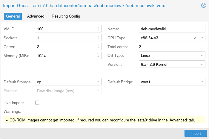
Proxmox VE provides an integrated VM importer using the storage plugin system for native integration into the API and web-based user interface. You can use this to import the VM as a whole, with most of its config mapped to Proxmox VE’s config model and reduced downtime.
|
|
The import wizard was added during the Proxmox VE 8.2 development cycle and is in tech preview state. While it’s already promising and working stable, it’s still under active development, focusing on adding other import-sources, like for example OVF/OVA files, in the future. |
To use the import wizard you have to first set up a new storage for an import source, you can do so on the web-interface under Datacenter → Storage → Add.
Then you can select the new storage in the resource tree and use the Virtual Guests content tab to see all available guests that can be imported.
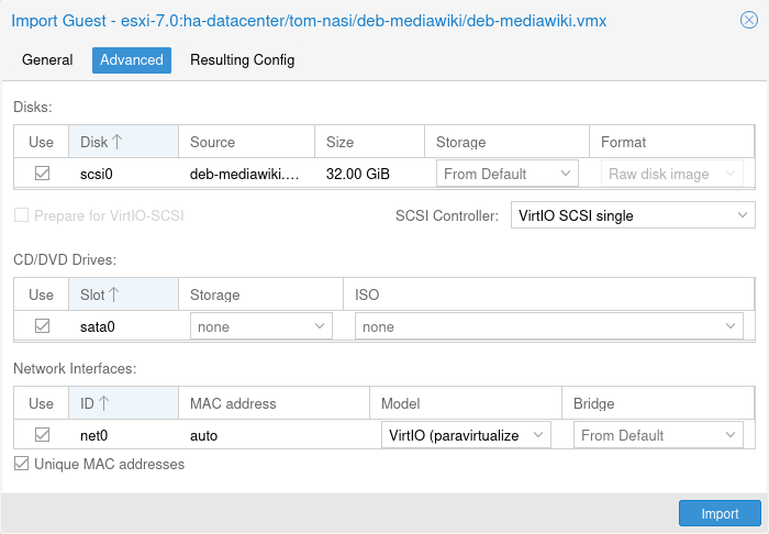
Select one and use the Import button (or double-click) to open the import wizard. You can modify a subset of the available options here and then start the import. Please note that you can do more advanced modifications after the import finished.
|
|
The import wizard is currently (2024-03) available for ESXi and has been tested with ESXi versions 6.5 through 8.0. Note that guests using vSAN storage cannot be directly imported directly; their disks must first be moved to another storage. While it is possible to use a vCenter as the import source, performance is dramatically degraded (5 to 10 times slower). |
For a step-by-step guide and tips for how to adapt the virtual guest to the new hyper-visor see our migrate to Proxmox VE wiki article.
10.7.2. Import OVF/OVA Through CLI
A VM export from a foreign hypervisor takes usually the form of one or more disk
images, with a configuration file describing the settings of the VM (RAM,
number of cores).
The disk images can be in the vmdk format, if the disks come from
VMware or VirtualBox, or qcow2 if the disks come from a KVM hypervisor.
The most popular configuration format for VM exports is the OVF standard, but in
practice interoperation is limited because many settings are not implemented in
the standard itself, and hypervisors export the supplementary information
in non-standard extensions.
Besides the problem of format, importing disk images from other hypervisors may fail if the emulated hardware changes too much from one hypervisor to another. Windows VMs are particularly concerned by this, as the OS is very picky about any changes of hardware. This problem may be solved by installing the MergeIDE.zip utility available from the Internet before exporting and choosing a hard disk type of IDE before booting the imported Windows VM.
Finally there is the question of paravirtualized drivers, which improve the speed of the emulated system and are specific to the hypervisor. GNU/Linux and other free Unix OSes have all the necessary drivers installed by default and you can switch to the paravirtualized drivers right after importing the VM. For Windows VMs, you need to install the Windows paravirtualized drivers by yourself.
GNU/Linux and other free Unix can usually be imported without hassle. Note that we cannot guarantee a successful import/export of Windows VMs in all cases due to the problems above.
Step-by-step example of a Windows OVF import
Microsoft provides Virtual Machines downloads to get started with Windows development.We are going to use one of these to demonstrate the OVF import feature.
Download the Virtual Machine zip
After getting informed about the user agreement, choose the Windows 10 Enterprise (Evaluation - Build) for the VMware platform, and download the zip.
Extract the disk image from the zip
Using the unzip utility or any archiver of your choice, unpack the zip, and copy via ssh/scp the ovf and vmdk files to your Proxmox VE host.
Import the Virtual Machine
This will create a new virtual machine, using cores, memory and VM name as read from the OVF manifest, and import the disks to the local-lvm storage. You have to configure the network manually.
# qm importovf 999 WinDev1709Eval.ovf local-lvm
The VM is ready to be started.
Adding an external disk image to a Virtual Machine
You can also add an existing disk image to a VM, either coming from a foreign hypervisor, or one that you created yourself.
Suppose you created a Debian/Ubuntu disk image with the vmdebootstrap tool:
vmdebootstrap --verbose \
 --size 10GiB --serial-console \
 --grub --no-extlinux \
 --package openssh-server \
 --package avahi-daemon \
 --package qemu-guest-agent \
 --hostname vm600 --enable-dhcp \
 --customize=./copy_pub_ssh.sh \
 --sparse --image vm600.raw
You can now create a new target VM, importing the image to the storage pvedir and attaching it to the VM’s SCSI controller:
# qm create 600 --net0 virtio,bridge=vmbr0 --name vm600 --serial0 socket \
   --boot order=scsi0 --scsihw virtio-scsi-pci --ostype l26 \
   --scsi0 pvedir:0,import-from=/path/to/dir/vm600.raw
The VM is ready to be started.
10.8. Cloud-Init Support
Cloud-Init is the de facto multi-distribution package that handles early initialization of a virtual machine instance. Using Cloud-Init, configuration of network devices and ssh keys on the hypervisor side is possible. When the VM starts for the first time, the Cloud-Init software inside the VM will apply those settings.
Many Linux distributions provide ready-to-use Cloud-Init images, mostly designed for OpenStack. These images will also work with Proxmox VE. While it may seem convenient to get such ready-to-use images, we usually recommended to prepare the images by yourself. The advantage is that you will know exactly what you have installed, and this helps you later to easily customize the image for your needs.
Once you have created such a Cloud-Init image we recommend to convert it into a VM template. From a VM template you can quickly create linked clones, so this is a fast method to roll out new VM instances. You just need to configure the network (and maybe the ssh keys) before you start the new VM.
We recommend using SSH key-based authentication to login to the VMs provisioned by Cloud-Init. It is also possible to set a password, but this is not as safe as using SSH key-based authentication because Proxmox VE needs to store an encrypted version of that password inside the Cloud-Init data.
Proxmox VE generates an ISO image to pass the Cloud-Init data to the VM. For that purpose, all Cloud-Init VMs need to have an assigned CD-ROM drive. Usually, a serial console should be added and used as a display. Many Cloud-Init images rely on this, it is a requirement for OpenStack. However, other images might have problems with this configuration. Switch back to the default display configuration if using a serial console doesn’t work.
10.8.1. Preparing Cloud-Init Templates
The first step is to prepare your VM. Basically you can use any VM. Simply install the Cloud-Init packages inside the VM that you want to prepare. On Debian/Ubuntu based systems this is as simple as:
apt-get install cloud-init
|
|
This command is not intended to be executed on the Proxmox VE host, but only inside the VM. |
Already many distributions provide ready-to-use Cloud-Init images (provided as .qcow2 files), so alternatively you can simply download and import such images. For the following example, we will use the cloud image provided by Ubuntu at https://cloud-images.ubuntu.com.
# download the image
wget https://cloud-images.ubuntu.com/bionic/current/bionic-server-cloudimg-amd64.img

# create a new VM with VirtIO SCSI controller
qm create 9000 --memory 2048 --net0 virtio,bridge=vmbr0 --scsihw virtio-scsi-pci

# import the downloaded disk to the local-lvm storage, attaching it as a SCSI drive
qm set 9000 --scsi0 local-lvm:0,import-from=/path/to/bionic-server-cloudimg-amd64.img
|
|
Ubuntu Cloud-Init images require the virtio-scsi-pci controller type for SCSI drives. |
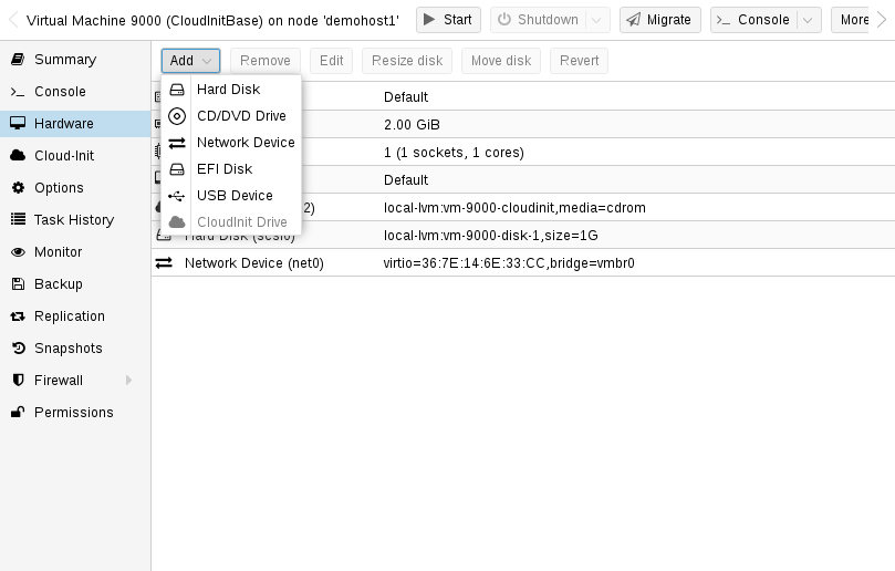
The next step is to configure a CD-ROM drive, which will be used to pass the Cloud-Init data to the VM.
qm set 9000 --ide2 local-lvm:cloudinit
To be able to boot directly from the Cloud-Init image, set the boot parameter to order=scsi0 to restrict BIOS to boot from this disk only. This will speed up booting, because VM BIOS skips the testing for a bootable CD-ROM.
qm set 9000 --boot order=scsi0
For many Cloud-Init images, it is required to configure a serial console and use it as a display. If the configuration doesn’t work for a given image however, switch back to the default display instead.
qm set 9000 --serial0 socket --vga serial0
In a last step, it is helpful to convert the VM into a template. From this template you can then quickly create linked clones. The deployment from VM templates is much faster than creating a full clone (copy).
qm template 9000
10.8.2. Deploying Cloud-Init Templates
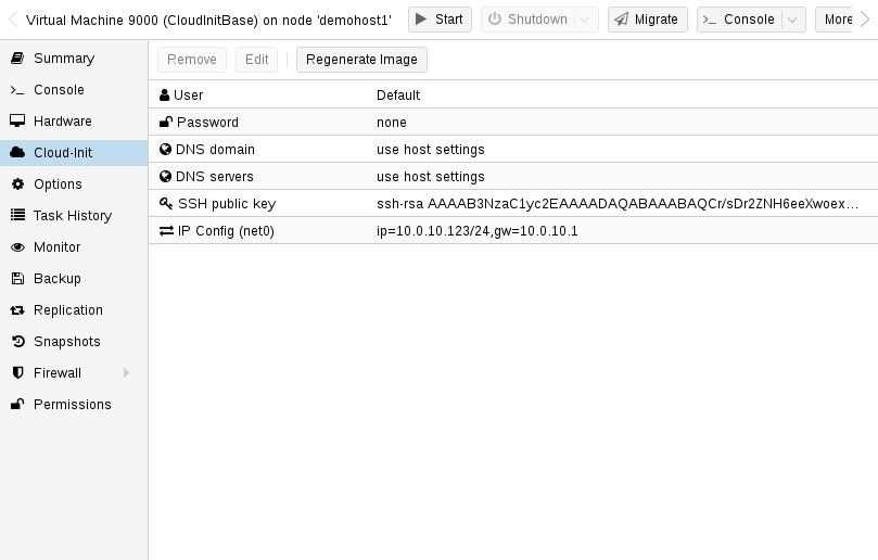
You can easily deploy such a template by cloning:
qm clone 9000 123 --name ubuntu2
Then configure the SSH public key used for authentication, and configure the IP setup:
qm set 123 --sshkey ~/.ssh/id_rsa.pub
qm set 123 --ipconfig0 ip=10.0.10.123/24,gw=10.0.10.1
You can also configure all the Cloud-Init options using a single command only. We have simply split the above example to separate the commands for reducing the line length. Also make sure to adopt the IP setup for your specific environment.
10.8.3. Custom Cloud-Init Configuration
The Cloud-Init integration also allows custom config files to be used instead of the automatically generated configs. This is done via the cicustom option on the command line:
qm set 9000 --cicustom "user=<volume>,network=<volume>,meta=<volume>"
The custom config files have to be on a storage that supports snippets and have to be available on all nodes the VM is going to be migrated to. Otherwise the VM won’t be able to start. For example:
qm set 9000 --cicustom "user=local:snippets/userconfig.yaml"
There are three kinds of configs for Cloud-Init. The first one is the user config as seen in the example above. The second is the network config and the third the meta config. They can all be specified together or mixed and matched however needed. The automatically generated config will be used for any that don’t have a custom config file specified.
The generated config can be dumped to serve as a base for custom configs:
qm cloudinit dump 9000 user
The same command exists for network and meta.
10.8.4. Cloud-Init specific Options
- cicustom: [meta=<volume>] [,network=<volume>] [,user=<volume>] [,vendor=<volume>]
-
Specify custom files to replace the automatically generated ones at start.
- meta=<volume>
-
Specify a custom file containing all meta data passed to the VM via" ." cloud-init. This is provider specific meaning configdrive2 and nocloud differ.
- network=<volume>
-
To pass a custom file containing all network data to the VM via cloud-init.
- user=<volume>
-
To pass a custom file containing all user data to the VM via cloud-init.
- vendor=<volume>
-
To pass a custom file containing all vendor data to the VM via cloud-init.
- cipassword: <string>
-
Password to assign the user. Using this is generally not recommended. Use ssh keys instead. Also note that older cloud-init versions do not support hashed passwords.
- citype: <configdrive2 | nocloud | opennebula>
-
Specifies the cloud-init configuration format. The default depends on the configured operating system type (ostype. We use the nocloud format for Linux, and configdrive2 for windows.
- ciupgrade: <boolean> (default = 1)
-
do an automatic package upgrade after the first boot.
- ciuser: <string>
-
User name to change ssh keys and password for instead of the image’s configured default user.
- ipconfig[n]: [gw=<GatewayIPv4>] [,gw6=<GatewayIPv6>] [,ip=<IPv4Format/CIDR>] [,ip6=<IPv6Format/CIDR>]
-
Specify IP addresses and gateways for the corresponding interface.
IP addresses use CIDR notation, gateways are optional but need an IP of the same type specified.
The special string dhcp can be used for IP addresses to use DHCP, in which case no explicit gateway should be provided. For IPv6 the special string auto can be used to use stateless autoconfiguration. This requires cloud-init 19.4 or newer.
If cloud-init is enabled and neither an IPv4 nor an IPv6 address is specified, it defaults to using dhcp on IPv4.
- gw=<GatewayIPv4>
-
Default gateway for IPv4 traffic.
Requires option(s): ip - gw6=<GatewayIPv6>
-
Default gateway for IPv6 traffic.
Requires option(s): ip6 - ip=<IPv4Format/CIDR> (default = dhcp)
-
IPv4 address in CIDR format.
- ip6=<IPv6Format/CIDR> (default = dhcp)
-
IPv6 address in CIDR format.
- nameserver: <string>
-
Sets DNS server IP address for a container. Create will automatically use the setting from the host if neither searchdomain nor nameserver are set.
- searchdomain: <string>
-
Sets DNS search domains for a container. Create will automatically use the setting from the host if neither searchdomain nor nameserver are set.
- sshkeys: <string>
-
Setup public SSH keys (one key per line, OpenSSH format).
10.9. PCI(e) Passthrough
PCI(e) passthrough is a mechanism to give a virtual machine control over a PCI device from the host. This can have some advantages over using virtualized hardware, for example lower latency, higher performance, or more features (e.g., offloading).
But, if you pass through a device to a virtual machine, you cannot use that device anymore on the host or in any other VM.
Note that, while PCI passthrough is available for i440fx and q35 machines, PCIe passthrough is only available on q35 machines. This does not mean that PCIe capable devices that are passed through as PCI devices will only run at PCI speeds. Passing through devices as PCIe just sets a flag for the guest to tell it that the device is a PCIe device instead of a "really fast legacy PCI device". Some guest applications benefit from this.
10.9.1. General Requirements
Since passthrough is performed on real hardware, it needs to fulfill some requirements. A brief overview of these requirements is given below, for more information on specific devices, see PCI Passthrough Examples.
Hardware
Your hardware needs to support IOMMU (I/O Memory Management Unit) interrupt remapping, this includes the CPU and the motherboard.
Generally, Intel systems with VT-d and AMD systems with AMD-Vi support this. But it is not guaranteed that everything will work out of the box, due to bad hardware implementation and missing or low quality drivers.
Further, server grade hardware has often better support than consumer grade hardware, but even then, many modern system can support this.
Please refer to your hardware vendor to check if they support this feature under Linux for your specific setup.
Determining PCI Card Address
The easiest way is to use the GUI to add a device of type "Host PCI" in the VM’s hardware tab. Alternatively, you can use the command line.
You can locate your card using
lspci
Configuration
Once you ensured that your hardware supports passthrough, you will need to do some configuration to enable PCI(e) passthrough.
First, you will have to enable IOMMU support in your BIOS/UEFI. Usually the corresponding setting is called IOMMU or VT-d, but you should find the exact option name in the manual of your motherboard.
For Intel CPUs, you also need to enable the IOMMU on the kernel command line kernels by adding:
intel_iommu=on
For AMD CPUs it should be enabled automatically.
If your hardware supports IOMMU passthrough mode, enabling this mode might increase performance. This is because VMs then bypass the (default) DMA translation normally performed by the hyper-visor and instead pass DMA requests directly to the hardware IOMMU. To enable these options, add:
iommu=pt
to the kernel commandline.
You have to make sure the following modules are loaded. This can be achieved by adding them to ‘/etc/modules’. In kernels newer than 6.2 (Proxmox VE 8 and onward) the vfio_virqfd module is part of the vfio module, therefore loading vfio_virqfd in Proxmox VE 8 and newer is not necessary.
 vfio
 vfio_iommu_type1
 vfio_pci
 vfio_virqfd #not needed if on kernel 6.2 or newer
After changing anything modules related, you need to refresh your initramfs. On Proxmox VE this can be done by executing:
# update-initramfs -u -k all
To check if the modules are being loaded, the output of
# lsmod | grep vfio
should include the four modules from above.
Finally reboot to bring the changes into effect and check that it is indeed enabled.
# dmesg | grep -e DMAR -e IOMMU -e AMD-Vi
should display that IOMMU, Directed I/O or Interrupt Remapping is enabled, depending on hardware and kernel the exact message can vary.
For notes on how to troubleshoot or verify if IOMMU is working as intended, please see the Verifying IOMMU Parameters section in our wiki.
It is also important that the device(s) you want to pass through are in a separate IOMMU group. This can be checked with a call to the Proxmox VE API:
# pvesh get /nodes/{nodename}/hardware/pci --pci-class-blacklist ""
It is okay if the device is in an IOMMU group together with its functions (e.g. a GPU with the HDMI Audio device) or with its root port or PCI(e) bridge.
|
|
PCI(e) slots
Some platforms handle their physical PCI(e) slots differently. So, sometimes it can help to put the card in a another PCI(e) slot, if you do not get the desired IOMMU group separation. |
|
|
Unsafe interrupts
For some platforms, it may be necessary to allow unsafe interrupts. For this add the following line in a file ending with ‘.conf’ file in /etc/modprobe.d/: options vfio_iommu_type1 allow_unsafe_interrupts=1 Please be aware that this option can make your system unstable. |
GPU Passthrough Notes
It is not possible to display the frame buffer of the GPU via NoVNC or SPICE on the Proxmox VE web interface.
When passing through a whole GPU or a vGPU and graphic output is wanted, one has to either physically connect a monitor to the card, or configure a remote desktop software (for example, VNC or RDP) inside the guest.
If you want to use the GPU as a hardware accelerator, for example, for programs using OpenCL or CUDA, this is not required.
10.9.2. Host Device Passthrough
The most used variant of PCI(e) passthrough is to pass through a whole PCI(e) card, for example a GPU or a network card.
Host Configuration
Proxmox VE tries to automatically make the PCI(e) device unavailable for the host. However, if this doesn’t work, there are two things that can be done:
-
pass the device IDs to the options of the vfio-pci modules by adding
options vfio-pci ids=1234:5678,4321:8765
to a .conf file in /etc/modprobe.d/ where 1234:5678 and 4321:8765 are the vendor and device IDs obtained by:
# lspci -nn
-
blacklist the driver on the host completely, ensuring that it is free to bind for passthrough, with
blacklist DRIVERNAME
in a .conf file in /etc/modprobe.d/.
To find the drivername, execute
# lspci -k
for example:
# lspci -k | grep -A 3 "VGA"
will output something similar to
01:00.0 VGA compatible controller: NVIDIA Corporation GP108 [GeForce GT 1030] (rev a1)
        Subsystem: Micro-Star International Co., Ltd. [MSI] GP108 [GeForce GT 1030]
        Kernel driver in use: <some-module>
        Kernel modules: <some-module>
Now we can blacklist the drivers by writing them into a .conf file:
echo "blacklist <some-module>" >> /etc/modprobe.d/blacklist.conf
For both methods you need to update the initramfs again and reboot after that.
Should this not work, you might need to set a soft dependency to load the gpu modules before loading vfio-pci. This can be done with the softdep flag, see also the manpages on modprobe.d for more information.
For example, if you are using drivers named <some-module>:
# echo "softdep <some-module> pre: vfio-pci" >> /etc/modprobe.d/<some-module>.conf
To check if your changes were successful, you can use
# lspci -nnk
and check your device entry. If it says
Kernel driver in use: vfio-pci
or the in use line is missing entirely, the device is ready to be used for passthrough.
VM Configuration
When passing through a GPU, the best compatibility is reached when using q35 as machine type, OVMF (UEFI for VMs) instead of SeaBIOS and PCIe instead of PCI. Note that if you want to use OVMF for GPU passthrough, the GPU needs to have an UEFI capable ROM, otherwise use SeaBIOS instead. To check if the ROM is UEFI capable, see the PCI Passthrough Examples wiki.
Furthermore, using OVMF, disabling vga arbitration may be possible, reducing the amount of legacy code needed to be run during boot. To disable vga arbitration:
echo "options vfio-pci ids=<vendor-id>,<device-id> disable_vga=1" > /etc/modprobe.d/vfio.conf
replacing the <vendor-id> and <device-id> with the ones obtained from:
# lspci -nn
PCI devices can be added in the web interface in the hardware section of the VM. Alternatively, you can use the command line; set the hostpciX option in the VM configuration, for example by executing:
# qm set VMID -hostpci0 00:02.0
or by adding a line to the VM configuration file:
hostpci0: 00:02.0
If your device has multiple functions (e.g., ‘00:02.0’ and ‘00:02.1’ ), you can pass them through all together with the shortened syntax ``00:02`. This is equivalent with checking the ``All Functions` checkbox in the web interface.
There are some options to which may be necessary, depending on the device and guest OS:
-
x-vga=on|off marks the PCI(e) device as the primary GPU of the VM. With this enabled the vga configuration option will be ignored.
-
pcie=on|off tells Proxmox VE to use a PCIe or PCI port. Some guests/device combination require PCIe rather than PCI. PCIe is only available for q35 machine types.
-
rombar=on|off makes the firmware ROM visible for the guest. Default is on. Some PCI(e) devices need this disabled.
-
romfile=<path>, is an optional path to a ROM file for the device to use. This is a relative path under /usr/share/kvm/.
An example of PCIe passthrough with a GPU set to primary:
# qm set VMID -hostpci0 02:00,pcie=on,x-vga=on
You can override the PCI vendor ID, device ID, and subsystem IDs that will be seen by the guest. This is useful if your device is a variant with an ID that your guest’s drivers don’t recognize, but you want to force those drivers to be loaded anyway (e.g. if you know your device shares the same chipset as a supported variant).
The available options are vendor-id, device-id, sub-vendor-id, and sub-device-id. You can set any or all of these to override your device’s default IDs.
For example:
# qm set VMID -hostpci0 02:00,device-id=0x10f6,sub-vendor-id=0x0000
10.9.3. SR-IOV
Another variant for passing through PCI(e) devices is to use the hardware virtualization features of your devices, if available.
|
|
Enabling SR-IOV
To use SR-IOV, platform support is especially important. It may be necessary to enable this feature in the BIOS/UEFI first, or to use a specific PCI(e) port for it to work. In doubt, consult the manual of the platform or contact its vendor. |
SR-IOV (Single-Root Input/Output Virtualization) enables a single device to provide multiple VF (Virtual Functions) to the system. Each of those VF can be used in a different VM, with full hardware features and also better performance and lower latency than software virtualized devices.
Currently, the most common use case for this are NICs (Network Interface Card) with SR-IOV support, which can provide multiple VFs per physical port. This allows using features such as checksum offloading, etc. to be used inside a VM, reducing the (host) CPU overhead.
Host Configuration
Generally, there are two methods for enabling virtual functions on a device.
-
sometimes there is an option for the driver module e.g. for some Intel drivers
max_vfs=4
which could be put file with .conf ending under /etc/modprobe.d/. (Do not forget to update your initramfs after that)
Please refer to your driver module documentation for the exact parameters and options.
-
The second, more generic, approach is using the sysfs. If a device and driver supports this you can change the number of VFs on the fly. For example, to setup 4 VFs on device 0000:01:00.0 execute:
# echo 4 > /sys/bus/pci/devices/0000:01:00.0/sriov_numvfs
To make this change persistent you can use the ‘sysfsutils` Debian package. After installation configure it via /etc/sysfs.conf or a `FILE.conf’ in /etc/sysfs.d/.
VM Configuration
After creating VFs, you should see them as separate PCI(e) devices when outputting them with lspci. Get their ID and pass them through like a normal PCI(e) device.
10.9.4. Mediated Devices (vGPU, GVT-g)
Mediated devices are another method to reuse features and performance from physical hardware for virtualized hardware. These are found most common in virtualized GPU setups such as Intel’s GVT-g and NVIDIA’s vGPUs used in their GRID technology.
With this, a physical Card is able to create virtual cards, similar to SR-IOV. The difference is that mediated devices do not appear as PCI(e) devices in the host, and are such only suited for using in virtual machines.
Host Configuration
In general your card’s driver must support that feature, otherwise it will not work. So please refer to your vendor for compatible drivers and how to configure them.
Intel’s drivers for GVT-g are integrated in the Kernel and should work with 5th, 6th and 7th generation Intel Core Processors, as well as E3 v4, E3 v5 and E3 v6 Xeon Processors.
To enable it for Intel Graphics, you have to make sure to load the module kvmgt (for example via /etc/modules) and to enable it on the Kernel commandline and add the following parameter:
i915.enable_gvt=1
After that remember to update the initramfs, and reboot your host.
VM Configuration
To use a mediated device, simply specify the mdev property on a hostpciX VM configuration option.
You can get the supported devices via the sysfs. For example, to list the supported types for the device 0000:00:02.0 you would simply execute:
# ls /sys/bus/pci/devices/0000:00:02.0/mdev_supported_types
Each entry is a directory which contains the following important files:
-
available_instances contains the amount of still available instances of this type, each mdev use in a VM reduces this.
-
description contains a short description about the capabilities of the type
-
create is the endpoint to create such a device, Proxmox VE does this automatically for you, if a hostpciX option with mdev is configured.
Example configuration with an Intel GVT-g vGPU (Intel Skylake 6700k):
# qm set VMID -hostpci0 00:02.0,mdev=i915-GVTg_V5_4
With this set, Proxmox VE automatically creates such a device on VM start, and cleans it up again when the VM stops.
10.9.5. Use in Clusters
It is also possible to map devices on a cluster level, so that they can be properly used with HA and hardware changes are detected and non root users can configure them. See Resource Mapping for details on that.
10.9.6. vIOMMU (emulated IOMMU)
vIOMMU is the emulation of a hardware IOMMU within a virtual machine, providing improved memory access control and security for virtualized I/O devices. Using the vIOMMU option also allows you to pass through PCI devices to level-2 VMs in level-1 VMs via Nested Virtualization. There are currently two vIOMMU implementations available: Intel and VirtIO.
Host requirement:
-
Add intel_iommu=on or amd_iommu=on depending on your CPU to your kernel command line.
Intel vIOMMU
Intel vIOMMU specific VM requirements:
-
Whether you are using an Intel or AMD CPU on your host, it is important to set intel_iommu=on in the VMs kernel parameters.
-
To use Intel vIOMMU you need to set q35 as the machine type.
If all requirements are met, you can add viommu=intel to the machine parameter in the configuration of the VM that should be able to pass through PCI devices.
# qm set VMID -machine q35,viommu=intel
VirtIO vIOMMU
This vIOMMU implementation is more recent and does not have as many limitations as Intel vIOMMU but is currently less used in production and less documentated.
With VirtIO vIOMMU there is no need to set any kernel parameters. It is also not necessary to use q35 as the machine type, but it is advisable if you want to use PCIe.
# qm set VMID -machine q35,viommu=virtio
10.10. Hookscripts
You can add a hook script to VMs with the config property hookscript.
# qm set 100 --hookscript local:snippets/hookscript.pl
It will be called during various phases of the guests lifetime. For an example and documentation see the example script under /usr/share/pve-docs/examples/guest-example-hookscript.pl.
10.11. Hibernation
You can suspend a VM to disk with the GUI option Hibernate or with
# qm suspend ID --todisk
That means that the current content of the memory will be saved onto disk and the VM gets stopped. On the next start, the memory content will be loaded and the VM can continue where it was left off.
If no target storage for the memory is given, it will be automatically chosen, the first of:
-
The storage vmstatestorage from the VM config.
-
The first shared storage from any VM disk.
-
The first non-shared storage from any VM disk.
-
The storage local as a fallback.
10.12. Resource Mapping
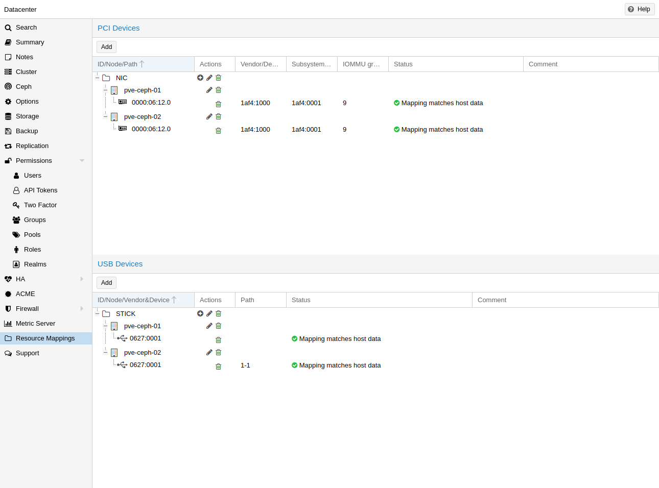
When using or referencing local resources (e.g. address of a pci device), using the raw address or id is sometimes problematic, for example:
-
when using HA, a different device with the same id or path may exist on the target node, and if one is not careful when assigning such guests to HA groups, the wrong device could be used, breaking configurations.
-
changing hardware can change ids and paths, so one would have to check all assigned devices and see if the path or id is still correct.
To handle this better, one can define cluster wide resource mappings, such that a resource has a cluster unique, user selected identifier which can correspond to different devices on different hosts. With this, HA won’t start a guest with a wrong device, and hardware changes can be detected.
Creating such a mapping can be done with the Proxmox VE web GUI under Datacenter in the relevant tab in the Resource Mappings category, or on the cli with
# pvesh create /cluster/mapping/<type> <options>
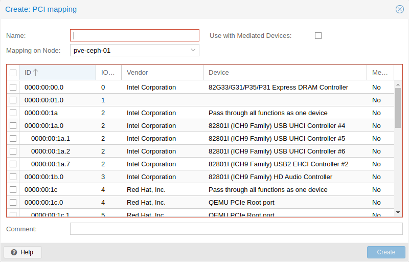
Where <type> is the hardware type (currently either pci or usb) and <options> are the device mappings and other configuration parameters.
Note that the options must include a map property with all identifying properties of that hardware, so that it’s possible to verify the hardware did not change and the correct device is passed through.
For example to add a PCI device as device1 with the path 0000:01:00.0 that has the device id 0001 and the vendor id 0002 on the node node1, and 0000:02:00.0 on node2 you can add it with:
# pvesh create /cluster/mapping/pci --id device1 \
 --map node=node1,path=0000:01:00.0,id=0002:0001 \
 --map node=node2,path=0000:02:00.0,id=0002:0001
You must repeat the map parameter for each node where that device should have a mapping (note that you can currently only map one USB device per node per mapping).
Using the GUI makes this much easier, as the correct properties are automatically picked up and sent to the API.
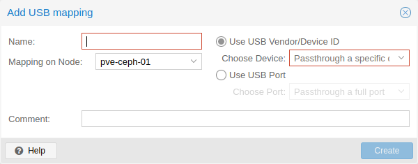
It’s also possible for PCI devices to provide multiple devices per node with multiple map properties for the nodes. If such a device is assigned to a guest, the first free one will be used when the guest is started. The order of the paths given is also the order in which they are tried, so arbitrary allocation policies can be implemented.
This is useful for devices with SR-IOV, since some times it is not important which exact virtual function is passed through.
You can assign such a device to a guest either with the GUI or with
# qm set ID -hostpci0 <name>
for PCI devices, or
# qm set <vmid> -usb0 <name>
for USB devices.
Where <vmid> is the guests id and <name> is the chosen name for the created mapping. All usual options for passing through the devices are allowed, such as mdev.
To create mappings Mapping.Modify on /mapping/<type>/<name> is necessary (where <type> is the device type and <name> is the name of the mapping).
To use these mappings, Mapping.Use on /mapping/<type>/<name> is necessary (in addition to the normal guest privileges to edit the configuration).
10.13. Managing Virtual Machines with qm
qm is the tool to manage QEMU/KVM virtual machines on Proxmox VE. You can create and destroy virtual machines, and control execution (start/stop/suspend/resume). Besides that, you can use qm to set parameters in the associated config file. It is also possible to create and delete virtual disks.
10.13.1. CLI Usage Examples
Using an iso file uploaded on the local storage, create a VM with a 4 GB IDE disk on the local-lvm storage
# qm create 300 -ide0 local-lvm:4 -net0 e1000 -cdrom local:iso/proxmox-mailgateway_2.1.iso
Start the new VM
# qm start 300
Send a shutdown request, then wait until the VM is stopped.
# qm shutdown 300 && qm wait 300
Same as above, but only wait for 40 seconds.
# qm shutdown 300 && qm wait 300 -timeout 40
If the VM does not shut down, force-stop it and overrule any running shutdown tasks. As stopping VMs may incur data loss, use it with caution.
# qm stop 300 -overrule-shutdown 1
Destroying a VM always removes it from Access Control Lists and it always removes the firewall configuration of the VM. You have to activate --purge, if you want to additionally remove the VM from replication jobs, backup jobs and HA resource configurations.
# qm destroy 300 --purge
Move a disk image to a different storage.
# qm move-disk 300 scsi0 other-storage
Reassign a disk image to a different VM. This will remove the disk scsi1 from the source VM and attaches it as scsi3 to the target VM. In the background the disk image is being renamed so that the name matches the new owner.
# qm move-disk 300 scsi1 --target-vmid 400 --target-disk scsi3
10.14. Configuration
VM configuration files are stored inside the Proxmox cluster file system, and can be accessed at /etc/pve/qemu-server/<VMID>.conf. Like other files stored inside /etc/pve/, they get automatically replicated to all other cluster nodes.
|
|
VMIDs < 100 are reserved for internal purposes, and VMIDs need to be unique cluster wide. |
boot: order=virtio0;net0
cores: 1
sockets: 1
memory: 512
name: webmail
ostype: l26
net0: e1000=EE:D2:28:5F:B6:3E,bridge=vmbr0
virtio0: local:vm-100-disk-1,size=32G
Those configuration files are simple text files, and you can edit them using a normal text editor (vi, nano, …). This is sometimes useful to do small corrections, but keep in mind that you need to restart the VM to apply such changes.
For that reason, it is usually better to use the qm command to generate and modify those files, or do the whole thing using the GUI. Our toolkit is smart enough to instantaneously apply most changes to running VM. This feature is called "hot plug", and there is no need to restart the VM in that case.
10.14.1. File Format
VM configuration files use a simple colon separated key/value format. Each line has the following format:
# this is a comment
OPTION: value
Blank lines in those files are ignored, and lines starting with a # character are treated as comments and are also ignored.
10.14.2. Snapshots
When you create a snapshot, qm stores the configuration at snapshot time into a separate snapshot section within the same configuration file. For example, after creating a snapshot called “testsnapshot”, your configuration file will look like this:
memory: 512
swap: 512
parent: testsnaphot
...

[testsnaphot]
memory: 512
swap: 512
snaptime: 1457170803
...
There are a few snapshot related properties like parent and snaptime. The parent property is used to store the parent/child relationship between snapshots. snaptime is the snapshot creation time stamp (Unix epoch).
You can optionally save the memory of a running VM with the option vmstate. For details about how the target storage gets chosen for the VM state, see State storage selection in the chapter Hibernation.
10.14.3. Options
- acpi: <boolean> (default = 1)
-
Enable/disable ACPI.
- affinity: <string>
-
List of host cores used to execute guest processes, for example: 0,5,8-11
- agent: [enabled=]<1|0> [,freeze-fs-on-backup=<1|0>] [,fstrim_cloned_disks=<1|0>] [,type=<virtio|isa>]
-
Enable/disable communication with the QEMU Guest Agent and its properties.
- enabled=<boolean> (default = 0)
-
Enable/disable communication with a QEMU Guest Agent (QGA) running in the VM.
- freeze-fs-on-backup=<boolean> (default = 1)
-
Freeze/thaw guest filesystems on backup for consistency.
- fstrim_cloned_disks=<boolean> (default = 0)
-
Run fstrim after moving a disk or migrating the VM.
- type=<isa | virtio> (default = virtio)
-
Select the agent type
- arch: <aarch64 | x86_64>
-
Virtual processor architecture. Defaults to the host.
- args: <string>
-
Arbitrary arguments passed to kvm, for example:
args: -no-reboot -smbios type=0,vendor=FOO
this option is for experts only. - audio0: device=<ich9-intel-hda|intel-hda|AC97> [,driver=<spice|none>]
-
Configure a audio device, useful in combination with QXL/Spice.
- device=<AC97 | ich9-intel-hda | intel-hda>
-
Configure an audio device.
- driver=<none | spice> (default = spice)
-
Driver backend for the audio device.
- autostart: <boolean> (default = 0)
-
Automatic restart after crash (currently ignored).
- balloon: <integer> (0 - N)
-
Amount of target RAM for the VM in MiB. Using zero disables the ballon driver.
- bios: <ovmf | seabios> (default = seabios)
-
Select BIOS implementation.
- boot: [[legacy=]<[acdn]{1,4}>] [,order=<device[;device...]>]
-
Specify guest boot order. Use the order= sub-property as usage with no key or legacy= is deprecated.
- legacy=<[acdn]{1,4}> (default = cdn)
-
Boot on floppy (a), hard disk (c), CD-ROM (d), or network (n). Deprecated, use order= instead.
- order=<device[;device...]>
-
The guest will attempt to boot from devices in the order they appear here.
Disks, optical drives and passed-through storage USB devices will be directly booted from, NICs will load PXE, and PCIe devices will either behave like disks (e.g. NVMe) or load an option ROM (e.g. RAID controller, hardware NIC).
Note that only devices in this list will be marked as bootable and thus loaded by the guest firmware (BIOS/UEFI). If you require multiple disks for booting (e.g. software-raid), you need to specify all of them here.
Overrides the deprecated legacy=[acdn]* value when given.
- bootdisk: (ide|sata|scsi|virtio)\d+
-
Enable booting from specified disk. Deprecated: Use boot: order=foo;bar instead.
- cdrom: <volume>
-
This is an alias for option -ide2
- cicustom: [meta=<volume>] [,network=<volume>] [,user=<volume>] [,vendor=<volume>]
-
cloud-init: Specify custom files to replace the automatically generated ones at start.
- meta=<volume>
-
Specify a custom file containing all meta data passed to the VM via" ." cloud-init. This is provider specific meaning configdrive2 and nocloud differ.
- network=<volume>
-
To pass a custom file containing all network data to the VM via cloud-init.
- user=<volume>
-
To pass a custom file containing all user data to the VM via cloud-init.
- vendor=<volume>
-
To pass a custom file containing all vendor data to the VM via cloud-init.
- cipassword: <string>
-
cloud-init: Password to assign the user. Using this is generally not recommended. Use ssh keys instead. Also note that older cloud-init versions do not support hashed passwords.
- citype: <configdrive2 | nocloud | opennebula>
-
Specifies the cloud-init configuration format. The default depends on the configured operating system type (ostype. We use the nocloud format for Linux, and configdrive2 for windows.
- ciupgrade: <boolean> (default = 1)
-
cloud-init: do an automatic package upgrade after the first boot.
- ciuser: <string>
-
cloud-init: User name to change ssh keys and password for instead of the image’s configured default user.
- cores: <integer> (1 - N) (default = 1)
-
The number of cores per socket.
- cpu: [[cputype=]<string>] [,flags=<+FLAG[;-FLAG...]>] [,hidden=<1|0>] [,hv-vendor-id=<vendor-id>] [,phys-bits=<8-64|host>] [,reported-model=<enum>]
-
Emulated CPU type.
- cputype=<string> (default = kvm64)
-
Emulated CPU type. Can be default or custom name (custom model names must be prefixed with custom-).
- flags=<+FLAG[;-FLAG...]>
-
List of additional CPU flags separated by ;. Use +FLAG to enable, -FLAG to disable a flag. Custom CPU models can specify any flag supported by QEMU/KVM, VM-specific flags must be from the following set for security reasons: pcid, spec-ctrl, ibpb, ssbd, virt-ssbd, amd-ssbd, amd-no-ssb, pdpe1gb, md-clear, hv-tlbflush, hv-evmcs, aes
- hidden=<boolean> (default = 0)
-
Do not identify as a KVM virtual machine.
- hv-vendor-id=<vendor-id>
-
The Hyper-V vendor ID. Some drivers or programs inside Windows guests need a specific ID.
- phys-bits=<8-64|host>
-
The physical memory address bits that are reported to the guest OS. Should be smaller or equal to the host’s. Set to host to use value from host CPU, but note that doing so will break live migration to CPUs with other values.
- reported-model=<486 | Broadwell | Broadwell-IBRS | Broadwell-noTSX | Broadwell-noTSX-IBRS | Cascadelake-Server | Cascadelake-Server-noTSX | Cascadelake-Server-v2 | Cascadelake-Server-v4 | Cascadelake-Server-v5 | Conroe | Cooperlake | Cooperlake-v2 | EPYC | EPYC-Genoa | EPYC-IBPB | EPYC-Milan | EPYC-Milan-v2 | EPYC-Rome | EPYC-Rome-v2 | EPYC-Rome-v3 | EPYC-Rome-v4 | EPYC-v3 | EPYC-v4 | GraniteRapids | Haswell | Haswell-IBRS | Haswell-noTSX | Haswell-noTSX-IBRS | Icelake-Client | Icelake-Client-noTSX | Icelake-Server | Icelake-Server-noTSX | Icelake-Server-v3 | Icelake-Server-v4 | Icelake-Server-v5 | Icelake-Server-v6 | IvyBridge | IvyBridge-IBRS | KnightsMill | Nehalem | Nehalem-IBRS | Opteron_G1 | Opteron_G2 | Opteron_G3 | Opteron_G4 | Opteron_G5 | Penryn | SandyBridge | SandyBridge-IBRS | SapphireRapids | SapphireRapids-v2 | Skylake-Client | Skylake-Client-IBRS | Skylake-Client-noTSX-IBRS | Skylake-Client-v4 | Skylake-Server | Skylake-Server-IBRS | Skylake-Server-noTSX-IBRS | Skylake-Server-v4 | Skylake-Server-v5 | Westmere | Westmere-IBRS | athlon | core2duo | coreduo | host | kvm32 | kvm64 | max | pentium | pentium2 | pentium3 | phenom | qemu32 | qemu64> (default = kvm64)
-
CPU model and vendor to report to the guest. Must be a QEMU/KVM supported model. Only valid for custom CPU model definitions, default models will always report themselves to the guest OS.
- cpulimit: <number> (0 - 128) (default = 0)
-
Limit of CPU usage.
If the computer has 2 CPUs, it has total of 2 CPU time. Value 0 indicates no CPU limit. - cpuunits: <integer> (1 - 262144) (default = cgroup v1: 1024, cgroup v2: 100)
-
CPU weight for a VM. Argument is used in the kernel fair scheduler. The larger the number is, the more CPU time this VM gets. Number is relative to weights of all the other running VMs.
- description: <string>
-
Description for the VM. Shown in the web-interface VM’s summary. This is saved as comment inside the configuration file.
- efidisk0: [file=]<volume> [,efitype=<2m|4m>] [,format=<enum>] [,pre-enrolled-keys=<1|0>] [,size=<DiskSize>]
-
Configure a disk for storing EFI vars.
- efitype=<2m | 4m> (default = 2m)
-
Size and type of the OVMF EFI vars. 4m is newer and recommended, and required for Secure Boot. For backwards compatibility, 2m is used if not otherwise specified. Ignored for VMs with arch=aarch64 (ARM).
- file=<volume>
-
The drive’s backing volume.
- format=<cloop | cow | qcow | qcow2 | qed | raw | vmdk>
-
The drive’s backing file’s data format.
- pre-enrolled-keys=<boolean> (default = 0)
-
Use am EFI vars template with distribution-specific and Microsoft Standard keys enrolled, if used with efitype=4m. Note that this will enable Secure Boot by default, though it can still be turned off from within the VM.
- size=<DiskSize>
-
Disk size. This is purely informational and has no effect.
- freeze: <boolean>
-
Freeze CPU at startup (use c monitor command to start execution).
- hookscript: <string>
-
Script that will be executed during various steps in the vms lifetime.
- hostpci[n]: [[host=]<HOSTPCIID[;HOSTPCIID2...]>] [,device-id=<hex id>] [,legacy-igd=<1|0>] [,mapping=<mapping-id>] [,mdev=<string>] [,pcie=<1|0>] [,rombar=<1|0>] [,romfile=<string>] [,sub-device-id=<hex id>] [,sub-vendor-id=<hex id>] [,vendor-id=<hex id>] [,x-vga=<1|0>]
-
Map host PCI devices into guest.
This option allows direct access to host hardware. So it is no longer possible to migrate such machines - use with special care.
Experimental! User reported problems with this option. - device-id=<hex id>
-
Override PCI device ID visible to guest
- host=<HOSTPCIID[;HOSTPCIID2...]>
-
Host PCI device pass through. The PCI ID of a host’s PCI device or a list of PCI virtual functions of the host. HOSTPCIID syntax is:
bus:dev.func (hexadecimal numbers)
You can us the lspci command to list existing PCI devices.
Either this or the mapping key must be set.
- legacy-igd=<boolean> (default = 0)
-
Pass this device in legacy IGD mode, making it the primary and exclusive graphics device in the VM. Requires pc-i440fx machine type and VGA set to none.
- mapping=<mapping-id>
-
The ID of a cluster wide mapping. Either this or the default-key host must be set.
- mdev=<string>
-
The type of mediated device to use. An instance of this type will be created on startup of the VM and will be cleaned up when the VM stops.
- pcie=<boolean> (default = 0)
-
Choose the PCI-express bus (needs the q35 machine model).
- rombar=<boolean> (default = 1)
-
Specify whether or not the device’s ROM will be visible in the guest’s memory map.
- romfile=<string>
-
Custom pci device rom filename (must be located in /usr/share/kvm/).
- sub-device-id=<hex id>
-
Override PCI subsystem device ID visible to guest
- sub-vendor-id=<hex id>
-
Override PCI subsystem vendor ID visible to guest
- vendor-id=<hex id>
-
Override PCI vendor ID visible to guest
- x-vga=<boolean> (default = 0)
-
Enable vfio-vga device support.
- hotplug: <string> (default = network,disk,usb)
-
Selectively enable hotplug features. This is a comma separated list of hotplug features: network, disk, cpu, memory, usb and cloudinit. Use 0 to disable hotplug completely. Using 1 as value is an alias for the default network,disk,usb. USB hotplugging is possible for guests with machine version >= 7.1 and ostype l26 or windows > 7.
- hugepages: <1024 | 2 | any>
-
Enable/disable hugepages memory.
- ide[n]: [file=]<volume> [,aio=<native|threads|io_uring>] [,backup=<1|0>] [,bps=<bps>] [,bps_max_length=<seconds>] [,bps_rd=<bps>] [,bps_rd_max_length=<seconds>] [,bps_wr=<bps>] [,bps_wr_max_length=<seconds>] [,cache=<enum>] [,cyls=<integer>] [,detect_zeroes=<1|0>] [,discard=<ignore|on>] [,format=<enum>] [,heads=<integer>] [,iops=<iops>] [,iops_max=<iops>] [,iops_max_length=<seconds>] [,iops_rd=<iops>] [,iops_rd_max=<iops>] [,iops_rd_max_length=<seconds>] [,iops_wr=<iops>] [,iops_wr_max=<iops>] [,iops_wr_max_length=<seconds>] [,mbps=<mbps>] [,mbps_max=<mbps>] [,mbps_rd=<mbps>] [,mbps_rd_max=<mbps>] [,mbps_wr=<mbps>] [,mbps_wr_max=<mbps>] [,media=<cdrom|disk>] [,model=<model>] [,replicate=<1|0>] [,rerror=<ignore|report|stop>] [,secs=<integer>] [,serial=<serial>] [,shared=<1|0>] [,size=<DiskSize>] [,snapshot=<1|0>] [,ssd=<1|0>] [,trans=<none|lba|auto>] [,werror=<enum>] [,wwn=<wwn>]
-
Use volume as IDE hard disk or CD-ROM (n is 0 to 3).
- aio=<io_uring | native | threads>
-
AIO type to use.
- backup=<boolean>
-
Whether the drive should be included when making backups.
- bps=<bps>
-
Maximum r/w speed in bytes per second.
- bps_max_length=<seconds>
-
Maximum length of I/O bursts in seconds.
- bps_rd=<bps>
-
Maximum read speed in bytes per second.
- bps_rd_max_length=<seconds>
-
Maximum length of read I/O bursts in seconds.
- bps_wr=<bps>
-
Maximum write speed in bytes per second.
- bps_wr_max_length=<seconds>
-
Maximum length of write I/O bursts in seconds.
- cache=<directsync | none | unsafe | writeback | writethrough>
-
The drive’s cache mode
- cyls=<integer>
-
Force the drive’s physical geometry to have a specific cylinder count.
- detect_zeroes=<boolean>
-
Controls whether to detect and try to optimize writes of zeroes.
- discard=<ignore | on>
-
Controls whether to pass discard/trim requests to the underlying storage.
- file=<volume>
-
The drive’s backing volume.
- format=<cloop | cow | qcow | qcow2 | qed | raw | vmdk>
-
The drive’s backing file’s data format.
- heads=<integer>
-
Force the drive’s physical geometry to have a specific head count.
- iops=<iops>
-
Maximum r/w I/O in operations per second.
- iops_max=<iops>
-
Maximum unthrottled r/w I/O pool in operations per second.
- iops_max_length=<seconds>
-
Maximum length of I/O bursts in seconds.
- iops_rd=<iops>
-
Maximum read I/O in operations per second.
- iops_rd_max=<iops>
-
Maximum unthrottled read I/O pool in operations per second.
- iops_rd_max_length=<seconds>
-
Maximum length of read I/O bursts in seconds.
- iops_wr=<iops>
-
Maximum write I/O in operations per second.
- iops_wr_max=<iops>
-
Maximum unthrottled write I/O pool in operations per second.
- iops_wr_max_length=<seconds>
-
Maximum length of write I/O bursts in seconds.
- mbps=<mbps>
-
Maximum r/w speed in megabytes per second.
- mbps_max=<mbps>
-
Maximum unthrottled r/w pool in megabytes per second.
- mbps_rd=<mbps>
-
Maximum read speed in megabytes per second.
- mbps_rd_max=<mbps>
-
Maximum unthrottled read pool in megabytes per second.
- mbps_wr=<mbps>
-
Maximum write speed in megabytes per second.
- mbps_wr_max=<mbps>
-
Maximum unthrottled write pool in megabytes per second.
- media=<cdrom | disk> (default = disk)
-
The drive’s media type.
- model=<model>
-
The drive’s reported model name, url-encoded, up to 40 bytes long.
- replicate=<boolean> (default = 1)
-
Whether the drive should considered for replication jobs.
- rerror=<ignore | report | stop>
-
Read error action.
- secs=<integer>
-
Force the drive’s physical geometry to have a specific sector count.
- serial=<serial>
-
The drive’s reported serial number, url-encoded, up to 20 bytes long.
- shared=<boolean> (default = 0)
-
Mark this locally-managed volume as available on all nodes.
This option does not share the volume automatically, it assumes it is shared already! - size=<DiskSize>
-
Disk size. This is purely informational and has no effect.
- snapshot=<boolean>
-
Controls qemu’s snapshot mode feature. If activated, changes made to the disk are temporary and will be discarded when the VM is shutdown.
- ssd=<boolean>
-
Whether to expose this drive as an SSD, rather than a rotational hard disk.
- trans=<auto | lba | none>
-
Force disk geometry bios translation mode.
- werror=<enospc | ignore | report | stop>
-
Write error action.
- wwn=<wwn>
-
The drive’s worldwide name, encoded as 16 bytes hex string, prefixed by 0x.
- ipconfig[n]: [gw=<GatewayIPv4>] [,gw6=<GatewayIPv6>] [,ip=<IPv4Format/CIDR>] [,ip6=<IPv6Format/CIDR>]
-
cloud-init: Specify IP addresses and gateways for the corresponding interface.
IP addresses use CIDR notation, gateways are optional but need an IP of the same type specified.
The special string dhcp can be used for IP addresses to use DHCP, in which case no explicit gateway should be provided. For IPv6 the special string auto can be used to use stateless autoconfiguration. This requires cloud-init 19.4 or newer.
If cloud-init is enabled and neither an IPv4 nor an IPv6 address is specified, it defaults to using dhcp on IPv4.
- gw=<GatewayIPv4>
-
Default gateway for IPv4 traffic.
Requires option(s): ip - gw6=<GatewayIPv6>
-
Default gateway for IPv6 traffic.
Requires option(s): ip6 - ip=<IPv4Format/CIDR> (default = dhcp)
-
IPv4 address in CIDR format.
- ip6=<IPv6Format/CIDR> (default = dhcp)
-
IPv6 address in CIDR format.
- ivshmem: size=<integer> [,name=<string>]
-
Inter-VM shared memory. Useful for direct communication between VMs, or to the host.
- name=<string>
-
The name of the file. Will be prefixed with pve-shm-. Default is the VMID. Will be deleted when the VM is stopped.
- size=<integer> (1 - N)
-
The size of the file in MB.
- keephugepages: <boolean> (default = 0)
-
Use together with hugepages. If enabled, hugepages will not not be deleted after VM shutdown and can be used for subsequent starts.
- keyboard: <da | de | de-ch | en-gb | en-us | es | fi | fr | fr-be | fr-ca | fr-ch | hu | is | it | ja | lt | mk | nl | no | pl | pt | pt-br | sl | sv | tr>
-
Keyboard layout for VNC server. This option is generally not required and is often better handled from within the guest OS.
- kvm: <boolean> (default = 1)
-
Enable/disable KVM hardware virtualization.
- localtime: <boolean>
-
Set the real time clock (RTC) to local time. This is enabled by default if the ostype indicates a Microsoft Windows OS.
- lock: <backup | clone | create | migrate | rollback | snapshot | snapshot-delete | suspended | suspending>
-
Lock/unlock the VM.
- machine: [[type=]<machine type>] [,viommu=<intel|virtio>]
-
Specify the QEMU machine.
- type=<machine type>
-
Specifies the QEMU machine type.
- viommu=<intel | virtio>
-
Enable and set guest vIOMMU variant (Intel vIOMMU needs q35 to be set as machine type).
- memory: [current=]<integer>
-
Memory properties.
- current=<integer> (16 - N) (default = 512)
-
Current amount of online RAM for the VM in MiB. This is the maximum available memory when you use the balloon device.
- migrate_downtime: <number> (0 - N) (default = 0.1)
-
Set maximum tolerated downtime (in seconds) for migrations.
- migrate_speed: <integer> (0 - N) (default = 0)
-
Set maximum speed (in MB/s) for migrations. Value 0 is no limit.
- name: <string>
-
Set a name for the VM. Only used on the configuration web interface.
- nameserver: <string>
-
cloud-init: Sets DNS server IP address for a container. Create will automatically use the setting from the host if neither searchdomain nor nameserver are set.
- net[n]: [model=]<enum> [,bridge=<bridge>] [,firewall=<1|0>] [,link_down=<1|0>] [,macaddr=<XX:XX:XX:XX:XX:XX>] [,mtu=<integer>] [,queues=<integer>] [,rate=<number>] [,tag=<integer>] [,trunks=<vlanid[;vlanid...]>] [,<model>=<macaddr>]
-
Specify network devices.
- bridge=<bridge>
-
Bridge to attach the network device to. The Proxmox VE standard bridge is called vmbr0.
If you do not specify a bridge, we create a kvm user (NATed) network device, which provides DHCP and DNS services. The following addresses are used:
10.0.2.2   Gateway
10.0.2.3   DNS Server
10.0.2.4   SMB Server
The DHCP server assign addresses to the guest starting from 10.0.2.15.
- firewall=<boolean>
-
Whether this interface should be protected by the firewall.
- link_down=<boolean>
-
Whether this interface should be disconnected (like pulling the plug).
- macaddr=<XX:XX:XX:XX:XX:XX>
-
A common MAC address with the I/G (Individual/Group) bit not set.
- model=<e1000 | e1000-82540em | e1000-82544gc | e1000-82545em | e1000e | i82551 | i82557b | i82559er | ne2k_isa | ne2k_pci | pcnet | rtl8139 | virtio | vmxnet3>
-
Network Card Model. The virtio model provides the best performance with very low CPU overhead. If your guest does not support this driver, it is usually best to use e1000.
- mtu=<integer> (1 - 65520)
-
Force MTU, for VirtIO only. Set to 1 to use the bridge MTU
- queues=<integer> (0 - 64)
-
Number of packet queues to be used on the device.
- rate=<number> (0 - N)
-
Rate limit in mbps (megabytes per second) as floating point number.
- tag=<integer> (1 - 4094)
-
VLAN tag to apply to packets on this interface.
- trunks=<vlanid[;vlanid...]>
-
VLAN trunks to pass through this interface.
- numa: <boolean> (default = 0)
-
Enable/disable NUMA.
- numa[n]: cpus=<id[-id];...> [,hostnodes=<id[-id];...>] [,memory=<number>] [,policy=<preferred|bind|interleave>]
-
NUMA topology.
- cpus=<id[-id];...>
-
CPUs accessing this NUMA node.
- hostnodes=<id[-id];...>
-
Host NUMA nodes to use.
- memory=<number>
-
Amount of memory this NUMA node provides.
- policy=<bind | interleave | preferred>
-
NUMA allocation policy.
- onboot: <boolean> (default = 0)
-
Specifies whether a VM will be started during system bootup.
- ostype: <l24 | l26 | other | solaris | w2k | w2k3 | w2k8 | win10 | win11 | win7 | win8 | wvista | wxp>
-
Specify guest operating system. This is used to enable special optimization/features for specific operating systems:
other
unspecified OS
wxp
Microsoft Windows XP
w2k
Microsoft Windows 2000
w2k3
Microsoft Windows 2003
w2k8
Microsoft Windows 2008
wvista
Microsoft Windows Vista
win7
Microsoft Windows 7
win8
Microsoft Windows 8/2012/2012r2
win10
Microsoft Windows 10/2016/2019
win11
Microsoft Windows 11/2022/2025
l24
Linux 2.4 Kernel
l26
Linux 2.6 - 6.X Kernel
solaris
Solaris/OpenSolaris/OpenIndiania kernel
- parallel[n]: /dev/parport\d+|/dev/usb/lp\d+
-
Map host parallel devices (n is 0 to 2).
This option allows direct access to host hardware. So it is no longer possible to migrate such machines - use with special care.
Experimental! User reported problems with this option. - protection: <boolean> (default = 0)
-
Sets the protection flag of the VM. This will disable the remove VM and remove disk operations.
- reboot: <boolean> (default = 1)
-
Allow reboot. If set to 0 the VM exit on reboot.
- rng0: [source=]</dev/urandom|/dev/random|/dev/hwrng> [,max_bytes=<integer>] [,period=<integer>]
-
Configure a VirtIO-based Random Number Generator.
- max_bytes=<integer> (default = 1024)
-
Maximum bytes of entropy allowed to get injected into the guest every period milliseconds. Prefer a lower value when using /dev/random as source. Use 0 to disable limiting (potentially dangerous!).
- period=<integer> (default = 1000)
-
Every period milliseconds the entropy-injection quota is reset, allowing the guest to retrieve another max_bytes of entropy.
- source=</dev/hwrng | /dev/random | /dev/urandom>
-
The file on the host to gather entropy from. In most cases /dev/urandom should be preferred over /dev/random to avoid entropy-starvation issues on the host. Using urandom does not decrease security in any meaningful way, as it’s still seeded from real entropy, and the bytes provided will most likely be mixed with real entropy on the guest as well. /dev/hwrng can be used to pass through a hardware RNG from the host.
- sata[n]: [file=]<volume> [,aio=<native|threads|io_uring>] [,backup=<1|0>] [,bps=<bps>] [,bps_max_length=<seconds>] [,bps_rd=<bps>] [,bps_rd_max_length=<seconds>] [,bps_wr=<bps>] [,bps_wr_max_length=<seconds>] [,cache=<enum>] [,cyls=<integer>] [,detect_zeroes=<1|0>] [,discard=<ignore|on>] [,format=<enum>] [,heads=<integer>] [,iops=<iops>] [,iops_max=<iops>] [,iops_max_length=<seconds>] [,iops_rd=<iops>] [,iops_rd_max=<iops>] [,iops_rd_max_length=<seconds>] [,iops_wr=<iops>] [,iops_wr_max=<iops>] [,iops_wr_max_length=<seconds>] [,mbps=<mbps>] [,mbps_max=<mbps>] [,mbps_rd=<mbps>] [,mbps_rd_max=<mbps>] [,mbps_wr=<mbps>] [,mbps_wr_max=<mbps>] [,media=<cdrom|disk>] [,replicate=<1|0>] [,rerror=<ignore|report|stop>] [,secs=<integer>] [,serial=<serial>] [,shared=<1|0>] [,size=<DiskSize>] [,snapshot=<1|0>] [,ssd=<1|0>] [,trans=<none|lba|auto>] [,werror=<enum>] [,wwn=<wwn>]
-
Use volume as SATA hard disk or CD-ROM (n is 0 to 5).
- aio=<io_uring | native | threads>
-
AIO type to use.
- backup=<boolean>
-
Whether the drive should be included when making backups.
- bps=<bps>
-
Maximum r/w speed in bytes per second.
- bps_max_length=<seconds>
-
Maximum length of I/O bursts in seconds.
- bps_rd=<bps>
-
Maximum read speed in bytes per second.
- bps_rd_max_length=<seconds>
-
Maximum length of read I/O bursts in seconds.
- bps_wr=<bps>
-
Maximum write speed in bytes per second.
- bps_wr_max_length=<seconds>
-
Maximum length of write I/O bursts in seconds.
- cache=<directsync | none | unsafe | writeback | writethrough>
-
The drive’s cache mode
- cyls=<integer>
-
Force the drive’s physical geometry to have a specific cylinder count.
- detect_zeroes=<boolean>
-
Controls whether to detect and try to optimize writes of zeroes.
- discard=<ignore | on>
-
Controls whether to pass discard/trim requests to the underlying storage.
- file=<volume>
-
The drive’s backing volume.
- format=<cloop | cow | qcow | qcow2 | qed | raw | vmdk>
-
The drive’s backing file’s data format.
- heads=<integer>
-
Force the drive’s physical geometry to have a specific head count.
- iops=<iops>
-
Maximum r/w I/O in operations per second.
- iops_max=<iops>
-
Maximum unthrottled r/w I/O pool in operations per second.
- iops_max_length=<seconds>
-
Maximum length of I/O bursts in seconds.
- iops_rd=<iops>
-
Maximum read I/O in operations per second.
- iops_rd_max=<iops>
-
Maximum unthrottled read I/O pool in operations per second.
- iops_rd_max_length=<seconds>
-
Maximum length of read I/O bursts in seconds.
- iops_wr=<iops>
-
Maximum write I/O in operations per second.
- iops_wr_max=<iops>
-
Maximum unthrottled write I/O pool in operations per second.
- iops_wr_max_length=<seconds>
-
Maximum length of write I/O bursts in seconds.
- mbps=<mbps>
-
Maximum r/w speed in megabytes per second.
- mbps_max=<mbps>
-
Maximum unthrottled r/w pool in megabytes per second.
- mbps_rd=<mbps>
-
Maximum read speed in megabytes per second.
- mbps_rd_max=<mbps>
-
Maximum unthrottled read pool in megabytes per second.
- mbps_wr=<mbps>
-
Maximum write speed in megabytes per second.
- mbps_wr_max=<mbps>
-
Maximum unthrottled write pool in megabytes per second.
- media=<cdrom | disk> (default = disk)
-
The drive’s media type.
- replicate=<boolean> (default = 1)
-
Whether the drive should considered for replication jobs.
- rerror=<ignore | report | stop>
-
Read error action.
- secs=<integer>
-
Force the drive’s physical geometry to have a specific sector count.
- serial=<serial>
-
The drive’s reported serial number, url-encoded, up to 20 bytes long.
- shared=<boolean> (default = 0)
-
Mark this locally-managed volume as available on all nodes.
This option does not share the volume automatically, it assumes it is shared already! - size=<DiskSize>
-
Disk size. This is purely informational and has no effect.
- snapshot=<boolean>
-
Controls qemu’s snapshot mode feature. If activated, changes made to the disk are temporary and will be discarded when the VM is shutdown.
- ssd=<boolean>
-
Whether to expose this drive as an SSD, rather than a rotational hard disk.
- trans=<auto | lba | none>
-
Force disk geometry bios translation mode.
- werror=<enospc | ignore | report | stop>
-
Write error action.
- wwn=<wwn>
-
The drive’s worldwide name, encoded as 16 bytes hex string, prefixed by 0x.
- scsi[n]: [file=]<volume> [,aio=<native|threads|io_uring>] [,backup=<1|0>] [,bps=<bps>] [,bps_max_length=<seconds>] [,bps_rd=<bps>] [,bps_rd_max_length=<seconds>] [,bps_wr=<bps>] [,bps_wr_max_length=<seconds>] [,cache=<enum>] [,cyls=<integer>] [,detect_zeroes=<1|0>] [,discard=<ignore|on>] [,format=<enum>] [,heads=<integer>] [,iops=<iops>] [,iops_max=<iops>] [,iops_max_length=<seconds>] [,iops_rd=<iops>] [,iops_rd_max=<iops>] [,iops_rd_max_length=<seconds>] [,iops_wr=<iops>] [,iops_wr_max=<iops>] [,iops_wr_max_length=<seconds>] [,iothread=<1|0>] [,mbps=<mbps>] [,mbps_max=<mbps>] [,mbps_rd=<mbps>] [,mbps_rd_max=<mbps>] [,mbps_wr=<mbps>] [,mbps_wr_max=<mbps>] [,media=<cdrom|disk>] [,product=<product>] [,queues=<integer>] [,replicate=<1|0>] [,rerror=<ignore|report|stop>] [,ro=<1|0>] [,scsiblock=<1|0>] [,secs=<integer>] [,serial=<serial>] [,shared=<1|0>] [,size=<DiskSize>] [,snapshot=<1|0>] [,ssd=<1|0>] [,trans=<none|lba|auto>] [,vendor=<vendor>] [,werror=<enum>] [,wwn=<wwn>]
-
Use volume as SCSI hard disk or CD-ROM (n is 0 to 30).
- aio=<io_uring | native | threads>
-
AIO type to use.
- backup=<boolean>
-
Whether the drive should be included when making backups.
- bps=<bps>
-
Maximum r/w speed in bytes per second.
- bps_max_length=<seconds>
-
Maximum length of I/O bursts in seconds.
- bps_rd=<bps>
-
Maximum read speed in bytes per second.
- bps_rd_max_length=<seconds>
-
Maximum length of read I/O bursts in seconds.
- bps_wr=<bps>
-
Maximum write speed in bytes per second.
- bps_wr_max_length=<seconds>
-
Maximum length of write I/O bursts in seconds.
- cache=<directsync | none | unsafe | writeback | writethrough>
-
The drive’s cache mode
- cyls=<integer>
-
Force the drive’s physical geometry to have a specific cylinder count.
- detect_zeroes=<boolean>
-
Controls whether to detect and try to optimize writes of zeroes.
- discard=<ignore | on>
-
Controls whether to pass discard/trim requests to the underlying storage.
- file=<volume>
-
The drive’s backing volume.
- format=<cloop | cow | qcow | qcow2 | qed | raw | vmdk>
-
The drive’s backing file’s data format.
- heads=<integer>
-
Force the drive’s physical geometry to have a specific head count.
- iops=<iops>
-
Maximum r/w I/O in operations per second.
- iops_max=<iops>
-
Maximum unthrottled r/w I/O pool in operations per second.
- iops_max_length=<seconds>
-
Maximum length of I/O bursts in seconds.
- iops_rd=<iops>
-
Maximum read I/O in operations per second.
- iops_rd_max=<iops>
-
Maximum unthrottled read I/O pool in operations per second.
- iops_rd_max_length=<seconds>
-
Maximum length of read I/O bursts in seconds.
- iops_wr=<iops>
-
Maximum write I/O in operations per second.
- iops_wr_max=<iops>
-
Maximum unthrottled write I/O pool in operations per second.
- iops_wr_max_length=<seconds>
-
Maximum length of write I/O bursts in seconds.
- iothread=<boolean>
-
Whether to use iothreads for this drive
- mbps=<mbps>
-
Maximum r/w speed in megabytes per second.
- mbps_max=<mbps>
-
Maximum unthrottled r/w pool in megabytes per second.
- mbps_rd=<mbps>
-
Maximum read speed in megabytes per second.
- mbps_rd_max=<mbps>
-
Maximum unthrottled read pool in megabytes per second.
- mbps_wr=<mbps>
-
Maximum write speed in megabytes per second.
- mbps_wr_max=<mbps>
-
Maximum unthrottled write pool in megabytes per second.
- media=<cdrom | disk> (default = disk)
-
The drive’s media type.
- product=<product>
-
The drive’s product name, up to 16 bytes long.
- queues=<integer> (2 - N)
-
Number of queues.
- replicate=<boolean> (default = 1)
-
Whether the drive should considered for replication jobs.
- rerror=<ignore | report | stop>
-
Read error action.
- ro=<boolean>
-
Whether the drive is read-only.
- scsiblock=<boolean> (default = 0)
-
whether to use scsi-block for full passthrough of host block device
can lead to I/O errors in combination with low memory or high memory fragmentation on host - secs=<integer>
-
Force the drive’s physical geometry to have a specific sector count.
- serial=<serial>
-
The drive’s reported serial number, url-encoded, up to 20 bytes long.
- shared=<boolean> (default = 0)
-
Mark this locally-managed volume as available on all nodes.
This option does not share the volume automatically, it assumes it is shared already! - size=<DiskSize>
-
Disk size. This is purely informational and has no effect.
- snapshot=<boolean>
-
Controls qemu’s snapshot mode feature. If activated, changes made to the disk are temporary and will be discarded when the VM is shutdown.
- ssd=<boolean>
-
Whether to expose this drive as an SSD, rather than a rotational hard disk.
- trans=<auto | lba | none>
-
Force disk geometry bios translation mode.
- vendor=<vendor>
-
The drive’s vendor name, up to 8 bytes long.
- werror=<enospc | ignore | report | stop>
-
Write error action.
- wwn=<wwn>
-
The drive’s worldwide name, encoded as 16 bytes hex string, prefixed by 0x.
- scsihw: <lsi | lsi53c810 | megasas | pvscsi | virtio-scsi-pci | virtio-scsi-single> (default = lsi)
-
SCSI controller model
- searchdomain: <string>
-
cloud-init: Sets DNS search domains for a container. Create will automatically use the setting from the host if neither searchdomain nor nameserver are set.
- serial[n]: (/dev/.+|socket)
-
Create a serial device inside the VM (n is 0 to 3), and pass through a host serial device (i.e. /dev/ttyS0), or create a unix socket on the host side (use qm terminal to open a terminal connection).
If you pass through a host serial device, it is no longer possible to migrate such machines - use with special care.
Experimental! User reported problems with this option. - shares: <integer> (0 - 50000) (default = 1000)
-
Amount of memory shares for auto-ballooning. The larger the number is, the more memory this VM gets. Number is relative to weights of all other running VMs. Using zero disables auto-ballooning. Auto-ballooning is done by pvestatd.
- smbios1: [base64=<1|0>] [,family=<Base64 encoded string>] [,manufacturer=<Base64 encoded string>] [,product=<Base64 encoded string>] [,serial=<Base64 encoded string>] [,sku=<Base64 encoded string>] [,uuid=<UUID>] [,version=<Base64 encoded string>]
-
Specify SMBIOS type 1 fields.
- base64=<boolean>
-
Flag to indicate that the SMBIOS values are base64 encoded
- family=<Base64 encoded string>
-
Set SMBIOS1 family string.
- manufacturer=<Base64 encoded string>
-
Set SMBIOS1 manufacturer.
- product=<Base64 encoded string>
-
Set SMBIOS1 product ID.
- serial=<Base64 encoded string>
-
Set SMBIOS1 serial number.
- sku=<Base64 encoded string>
-
Set SMBIOS1 SKU string.
- uuid=<UUID>
-
Set SMBIOS1 UUID.
- version=<Base64 encoded string>
-
Set SMBIOS1 version.
- smp: <integer> (1 - N) (default = 1)
-
The number of CPUs. Please use option -sockets instead.
- sockets: <integer> (1 - N) (default = 1)
-
The number of CPU sockets.
- spice_enhancements: [foldersharing=<1|0>] [,videostreaming=<off|all|filter>]
-
Configure additional enhancements for SPICE.
- foldersharing=<boolean> (default = 0)
-
Enable folder sharing via SPICE. Needs Spice-WebDAV daemon installed in the VM.
- videostreaming=<all | filter | off> (default = off)
-
Enable video streaming. Uses compression for detected video streams.
- sshkeys: <string>
-
cloud-init: Setup public SSH keys (one key per line, OpenSSH format).
- startdate: (now | YYYY-MM-DD | YYYY-MM-DDTHH:MM:SS) (default = now)
-
Set the initial date of the real time clock. Valid format for date are:'now' or 2006-06-17T16:01:21 or 2006-06-17.
- startup: `[[order=]\d+] [,up=\d+] [,down=\d+] `
-
Startup and shutdown behavior. Order is a non-negative number defining the general startup order. Shutdown in done with reverse ordering. Additionally you can set the up or down delay in seconds, which specifies a delay to wait before the next VM is started or stopped.
- tablet: <boolean> (default = 1)
-
Enable/disable the USB tablet device. This device is usually needed to allow absolute mouse positioning with VNC. Else the mouse runs out of sync with normal VNC clients. If you’re running lots of console-only guests on one host, you may consider disabling this to save some context switches. This is turned off by default if you use spice (qm set <vmid> --vga qxl).
- tags: <string>
-
Tags of the VM. This is only meta information.
- tdf: <boolean> (default = 0)
-
Enable/disable time drift fix.
- template: <boolean> (default = 0)
-
Enable/disable Template.
- tpmstate0: [file=]<volume> [,size=<DiskSize>] [,version=<v1.2|v2.0>]
-
Configure a Disk for storing TPM state. The format is fixed to raw.
- file=<volume>
-
The drive’s backing volume.
- size=<DiskSize>
-
Disk size. This is purely informational and has no effect.
- version=<v1.2 | v2.0> (default = v2.0)
-
The TPM interface version. v2.0 is newer and should be preferred. Note that this cannot be changed later on.
- unused[n]: [file=]<volume>
-
Reference to unused volumes. This is used internally, and should not be modified manually.
- file=<volume>
-
The drive’s backing volume.
- usb[n]: [[host=]<HOSTUSBDEVICE|spice>] [,mapping=<mapping-id>] [,usb3=<1|0>]
-
Configure an USB device (n is 0 to 4, for machine version >= 7.1 and ostype l26 or windows > 7, n can be up to 14).
- host=<HOSTUSBDEVICE|spice>
-
The Host USB device or port or the value spice. HOSTUSBDEVICE syntax is:
'bus-port(.port)*' (decimal numbers) or
'vendor_id:product_id' (hexadeciaml numbers) or
'spice'
You can use the lsusb -t command to list existing usb devices.
This option allows direct access to host hardware. So it is no longer possible to migrate such machines - use with special care. The value spice can be used to add a usb redirection devices for spice.
Either this or the mapping key must be set.
- mapping=<mapping-id>
-
The ID of a cluster wide mapping. Either this or the default-key host must be set.
- usb3=<boolean> (default = 0)
-
Specifies whether if given host option is a USB3 device or port. For modern guests (machine version >= 7.1 and ostype l26 and windows > 7), this flag is irrelevant (all devices are plugged into a xhci controller).
- vcpus: <integer> (1 - N) (default = 0)
-
Number of hotplugged vcpus.
- vga: [[type=]<enum>] [,clipboard=<vnc>] [,memory=<integer>]
-
Configure the VGA Hardware. If you want to use high resolution modes (>= 1280x1024x16) you may need to increase the vga memory option. Since QEMU 2.9 the default VGA display type is std for all OS types besides some Windows versions (XP and older) which use cirrus. The qxl option enables the SPICE display server. For win* OS you can select how many independent displays you want, Linux guests can add displays them self. You can also run without any graphic card, using a serial device as terminal.
- clipboard=<vnc>
-
Enable a specific clipboard. If not set, depending on the display type the SPICE one will be added. Migration with VNC clipboard is not yet supported!
- memory=<integer> (4 - 512)
-
Sets the VGA memory (in MiB). Has no effect with serial display.
- type=<cirrus | none | qxl | qxl2 | qxl3 | qxl4 | serial0 | serial1 | serial2 | serial3 | std | virtio | virtio-gl | vmware> (default = std)
-
Select the VGA type.
- virtio[n]: [file=]<volume> [,aio=<native|threads|io_uring>] [,backup=<1|0>] [,bps=<bps>] [,bps_max_length=<seconds>] [,bps_rd=<bps>] [,bps_rd_max_length=<seconds>] [,bps_wr=<bps>] [,bps_wr_max_length=<seconds>] [,cache=<enum>] [,cyls=<integer>] [,detect_zeroes=<1|0>] [,discard=<ignore|on>] [,format=<enum>] [,heads=<integer>] [,iops=<iops>] [,iops_max=<iops>] [,iops_max_length=<seconds>] [,iops_rd=<iops>] [,iops_rd_max=<iops>] [,iops_rd_max_length=<seconds>] [,iops_wr=<iops>] [,iops_wr_max=<iops>] [,iops_wr_max_length=<seconds>] [,iothread=<1|0>] [,mbps=<mbps>] [,mbps_max=<mbps>] [,mbps_rd=<mbps>] [,mbps_rd_max=<mbps>] [,mbps_wr=<mbps>] [,mbps_wr_max=<mbps>] [,media=<cdrom|disk>] [,replicate=<1|0>] [,rerror=<ignore|report|stop>] [,ro=<1|0>] [,secs=<integer>] [,serial=<serial>] [,shared=<1|0>] [,size=<DiskSize>] [,snapshot=<1|0>] [,trans=<none|lba|auto>] [,werror=<enum>]
-
Use volume as VIRTIO hard disk (n is 0 to 15).
- aio=<io_uring | native | threads>
-
AIO type to use.
- backup=<boolean>
-
Whether the drive should be included when making backups.
- bps=<bps>
-
Maximum r/w speed in bytes per second.
- bps_max_length=<seconds>
-
Maximum length of I/O bursts in seconds.
- bps_rd=<bps>
-
Maximum read speed in bytes per second.
- bps_rd_max_length=<seconds>
-
Maximum length of read I/O bursts in seconds.
- bps_wr=<bps>
-
Maximum write speed in bytes per second.
- bps_wr_max_length=<seconds>
-
Maximum length of write I/O bursts in seconds.
- cache=<directsync | none | unsafe | writeback | writethrough>
-
The drive’s cache mode
- cyls=<integer>
-
Force the drive’s physical geometry to have a specific cylinder count.
- detect_zeroes=<boolean>
-
Controls whether to detect and try to optimize writes of zeroes.
- discard=<ignore | on>
-
Controls whether to pass discard/trim requests to the underlying storage.
- file=<volume>
-
The drive’s backing volume.
- format=<cloop | cow | qcow | qcow2 | qed | raw | vmdk>
-
The drive’s backing file’s data format.
- heads=<integer>
-
Force the drive’s physical geometry to have a specific head count.
- iops=<iops>
-
Maximum r/w I/O in operations per second.
- iops_max=<iops>
-
Maximum unthrottled r/w I/O pool in operations per second.
- iops_max_length=<seconds>
-
Maximum length of I/O bursts in seconds.
- iops_rd=<iops>
-
Maximum read I/O in operations per second.
- iops_rd_max=<iops>
-
Maximum unthrottled read I/O pool in operations per second.
- iops_rd_max_length=<seconds>
-
Maximum length of read I/O bursts in seconds.
- iops_wr=<iops>
-
Maximum write I/O in operations per second.
- iops_wr_max=<iops>
-
Maximum unthrottled write I/O pool in operations per second.
- iops_wr_max_length=<seconds>
-
Maximum length of write I/O bursts in seconds.
- iothread=<boolean>
-
Whether to use iothreads for this drive
- mbps=<mbps>
-
Maximum r/w speed in megabytes per second.
- mbps_max=<mbps>
-
Maximum unthrottled r/w pool in megabytes per second.
- mbps_rd=<mbps>
-
Maximum read speed in megabytes per second.
- mbps_rd_max=<mbps>
-
Maximum unthrottled read pool in megabytes per second.
- mbps_wr=<mbps>
-
Maximum write speed in megabytes per second.
- mbps_wr_max=<mbps>
-
Maximum unthrottled write pool in megabytes per second.
- media=<cdrom | disk> (default = disk)
-
The drive’s media type.
- replicate=<boolean> (default = 1)
-
Whether the drive should considered for replication jobs.
- rerror=<ignore | report | stop>
-
Read error action.
- ro=<boolean>
-
Whether the drive is read-only.
- secs=<integer>
-
Force the drive’s physical geometry to have a specific sector count.
- serial=<serial>
-
The drive’s reported serial number, url-encoded, up to 20 bytes long.
- shared=<boolean> (default = 0)
-
Mark this locally-managed volume as available on all nodes.
This option does not share the volume automatically, it assumes it is shared already! - size=<DiskSize>
-
Disk size. This is purely informational and has no effect.
- snapshot=<boolean>
-
Controls qemu’s snapshot mode feature. If activated, changes made to the disk are temporary and will be discarded when the VM is shutdown.
- trans=<auto | lba | none>
-
Force disk geometry bios translation mode.
- werror=<enospc | ignore | report | stop>
-
Write error action.
- vmgenid: <UUID> (default = 1 (autogenerated))
-
The VM generation ID (vmgenid) device exposes a 128-bit integer value identifier to the guest OS. This allows to notify the guest operating system when the virtual machine is executed with a different configuration (e.g. snapshot execution or creation from a template). The guest operating system notices the change, and is then able to react as appropriate by marking its copies of distributed databases as dirty, re-initializing its random number generator, etc. Note that auto-creation only works when done through API/CLI create or update methods, but not when manually editing the config file.
- vmstatestorage: <storage ID>
-
Default storage for VM state volumes/files.
- watchdog: [[model=]<i6300esb|ib700>] [,action=<enum>]
-
Create a virtual hardware watchdog device. Once enabled (by a guest action), the watchdog must be periodically polled by an agent inside the guest or else the watchdog will reset the guest (or execute the respective action specified)
- action=<debug | none | pause | poweroff | reset | shutdown>
-
The action to perform if after activation the guest fails to poll the watchdog in time.
- model=<i6300esb | ib700> (default = i6300esb)
-
Watchdog type to emulate.
10.15. Locks
Online migrations, snapshots and backups (vzdump) set a lock to prevent incompatible concurrent actions on the affected VMs. Sometimes you need to remove such a lock manually (for example after a power failure).
# qm unlock <vmid>
|
|
Only do that if you are sure the action which set the lock is no longer running. |
11. Proxmox Container Toolkit
Containers are a lightweight alternative to fully virtualized machines (VMs). They use the kernel of the host system that they run on, instead of emulating a full operating system (OS). This means that containers can access resources on the host system directly.
The runtime costs for containers is low, usually negligible. However, there are some drawbacks that need be considered:
-
Only Linux distributions can be run in Proxmox Containers. It is not possible to run other operating systems like, for example, FreeBSD or Microsoft Windows inside a container.
-
For security reasons, access to host resources needs to be restricted. Therefore, containers run in their own separate namespaces. Additionally some syscalls (user space requests to the Linux kernel) are not allowed within containers.
Proxmox VE uses Linux Containers (LXC) as its underlying container technology. The “Proxmox Container Toolkit” (pct) simplifies the usage and management of LXC, by providing an interface that abstracts complex tasks.
Containers are tightly integrated with Proxmox VE. This means that they are aware of the cluster setup, and they can use the same network and storage resources as virtual machines. You can also use the Proxmox VE firewall, or manage containers using the HA framework.
Our primary goal is to offer an environment that provides the benefits of using a VM, but without the additional overhead. This means that Proxmox Containers can be categorized as “System Containers”, rather than “Application Containers”.
|
|
If you want to run application containers, for example, Docker images, it is recommended that you run them inside a Proxmox QEMU VM. This will give you all the advantages of application containerization, while also providing the benefits that VMs offer, such as strong isolation from the host and the ability to live-migrate, which otherwise isn’t possible with containers. |
11.1. Technology Overview
-
Integrated into Proxmox VE graphical web user interface (GUI)
-
Easy to use command-line tool pct
-
Access via Proxmox VE REST API
-
lxcfs to provide containerized /proc file system
-
Control groups (cgroups) for resource isolation and limitation
-
AppArmor and seccomp to improve security
-
Modern Linux kernels
-
Image based deployment (templates)
-
Uses Proxmox VE storage library
-
Container setup from host (network, DNS, storage, etc.)
11.2. Supported Distributions
List of officially supported distributions can be found below.
Templates for the following distributions are available through our repositories. You can use pveam tool or the Graphical User Interface to download them.
11.2.1. Alpine Linux
Alpine Linux is a security-oriented, lightweight Linux distribution based on musl libc and busybox.
For currently supported releases see:
11.2.2. Arch Linux
Arch Linux, a lightweight and flexible Linux® distribution that tries to Keep It Simple.
Arch Linux is using a rolling-release model, see its wiki for more details:
11.2.3. CentOS, Almalinux, Rocky Linux
CentOS / CentOS Stream
The CentOS Linux distribution is a stable, predictable, manageable and reproducible platform derived from the sources of Red Hat Enterprise Linux (RHEL)
For currently supported releases see:
Almalinux
An Open Source, community owned and governed, forever-free enterprise Linux distribution, focused on long-term stability, providing a robust production-grade platform. AlmaLinux OS is 1:1 binary compatible with RHEL® and pre-Stream CentOS.
For currently supported releases see:
Rocky Linux
Rocky Linux is a community enterprise operating system designed to be 100% bug-for-bug compatible with America’s top enterprise Linux distribution now that its downstream partner has shifted direction.
For currently supported releases see:
11.2.4. Debian
Debian is a free operating system, developed and maintained by the Debian project. A free Linux distribution with thousands of applications to meet our users' needs.
For currently supported releases see:
11.2.5. Devuan
Devuan GNU+Linux is a fork of Debian without systemd that allows users to reclaim control over their system by avoiding unnecessary entanglements and ensuring Init Freedom.
For currently supported releases see:
11.2.6. Fedora
Fedora creates an innovative, free, and open source platform for hardware, clouds, and containers that enables software developers and community members to build tailored solutions for their users.
For currently supported releases see:
11.2.7. Gentoo
a highly flexible, source-based Linux distribution.
Gentoo is using a rolling-release model.
11.2.8. OpenSUSE
The makers' choice for sysadmins, developers and desktop users.
For currently supported releases see:
11.2.9. Ubuntu
Ubuntu is the modern, open source operating system on Linux for the enterprise server, desktop, cloud, and IoT.
For currently supported releases see:
11.3. Container Images
Container images, sometimes also referred to as “templates” or “appliances”, are tar archives which contain everything to run a container.
Proxmox VE itself provides a variety of basic templates for the most common Linux distributions. They can be downloaded using the GUI or the pveam (short for Proxmox VE Appliance Manager) command-line utility. Additionally, TurnKey Linux container templates are also available to download.
The list of available templates is updated daily through the pve-daily-update timer. You can also trigger an update manually by executing:
# pveam update
To view the list of available images run:
# pveam available
You can restrict this large list by specifying the section you are interested in, for example basic system images:
# pveam available --section system
system          alpine-3.12-default_20200823_amd64.tar.xz
system          alpine-3.13-default_20210419_amd64.tar.xz
system          alpine-3.14-default_20210623_amd64.tar.xz
system          archlinux-base_20210420-1_amd64.tar.gz
system          centos-7-default_20190926_amd64.tar.xz
system          centos-8-default_20201210_amd64.tar.xz
system          debian-9.0-standard_9.7-1_amd64.tar.gz
system          debian-10-standard_10.7-1_amd64.tar.gz
system          devuan-3.0-standard_3.0_amd64.tar.gz
system          fedora-33-default_20201115_amd64.tar.xz
system          fedora-34-default_20210427_amd64.tar.xz
system          gentoo-current-default_20200310_amd64.tar.xz
system          opensuse-15.2-default_20200824_amd64.tar.xz
system          ubuntu-16.04-standard_16.04.5-1_amd64.tar.gz
system          ubuntu-18.04-standard_18.04.1-1_amd64.tar.gz
system          ubuntu-20.04-standard_20.04-1_amd64.tar.gz
system          ubuntu-20.10-standard_20.10-1_amd64.tar.gz
system          ubuntu-21.04-standard_21.04-1_amd64.tar.gz
Before you can use such a template, you need to download them into one of your storages. If you’re unsure to which one, you can simply use the local named storage for that purpose. For clustered installations, it is preferred to use a shared storage so that all nodes can access those images.
# pveam download local debian-10.0-standard_10.0-1_amd64.tar.gz
You are now ready to create containers using that image, and you can list all downloaded images on storage local with:
# pveam list local
local:vztmpl/debian-10.0-standard_10.0-1_amd64.tar.gz  219.95MB
|
|
You can also use the Proxmox VE web interface GUI to download, list and delete container templates. |
pct uses them to create a new container, for example:
# pct create 999 local:vztmpl/debian-10.0-standard_10.0-1_amd64.tar.gz
The above command shows you the full Proxmox VE volume identifiers. They include the storage name, and most other Proxmox VE commands can use them. For example you can delete that image later with:
# pveam remove local:vztmpl/debian-10.0-standard_10.0-1_amd64.tar.gz
11.4. Container Settings
11.4.1. General Settings
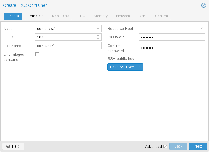
General settings of a container include
-
the Node : the physical server on which the container will run
-
the CT ID: a unique number in this Proxmox VE installation used to identify your container
-
Hostname: the hostname of the container
-
Resource Pool: a logical group of containers and VMs
-
Password: the root password of the container
-
SSH Public Key: a public key for connecting to the root account over SSH
-
Unprivileged container: this option allows to choose at creation time if you want to create a privileged or unprivileged container.
Unprivileged Containers
Unprivileged containers use a new kernel feature called user namespaces. The root UID 0 inside the container is mapped to an unprivileged user outside the container. This means that most security issues (container escape, resource abuse, etc.) in these containers will affect a random unprivileged user, and would be a generic kernel security bug rather than an LXC issue. The LXC team thinks unprivileged containers are safe by design.
This is the default option when creating a new container.
|
|
If the container uses systemd as an init system, please be aware the systemd version running inside the container should be equal to or greater than 220. |
Privileged Containers
Security in containers is achieved by using mandatory access control AppArmor restrictions, seccomp filters and Linux kernel namespaces. The LXC team considers this kind of container as unsafe, and they will not consider new container escape exploits to be security issues worthy of a CVE and quick fix. That’s why privileged containers should only be used in trusted environments.
11.4.2. CPU
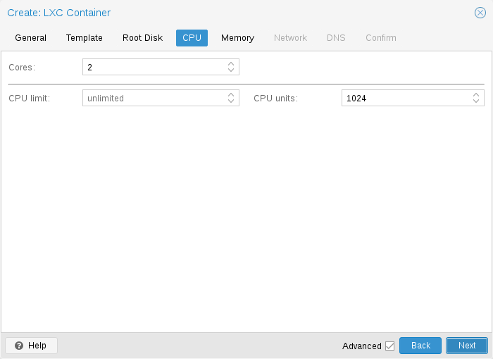
You can restrict the number of visible CPUs inside the container using the cores option. This is implemented using the Linux cpuset cgroup (control group). A special task inside pvestatd tries to distribute running containers among available CPUs periodically. To view the assigned CPUs run the following command:
# pct cpusets
 ---------------------
 102:              6 7
 105:      2 3 4 5
 108:  0 1
 ---------------------
Containers use the host kernel directly. All tasks inside a container are handled by the host CPU scheduler. Proxmox VE uses the Linux CFS (Completely Fair Scheduler) scheduler by default, which has additional bandwidth control options.
|
cpulimit:
|
You can use this option to further limit assigned CPU time. Please note that this is a floating point number, so it is perfectly valid to assign two cores to a container, but restrict overall CPU consumption to half a core. cores: 2 cpulimit: 0.5 |
|
cpuunits:
|
This is a relative weight passed to the kernel scheduler. The larger the number is, the more CPU time this container gets. Number is relative to the weights of all the other running containers. The default is 100 (or 1024 if the host uses legacy cgroup v1). You can use this setting to prioritize some containers. |
11.4.3. Memory
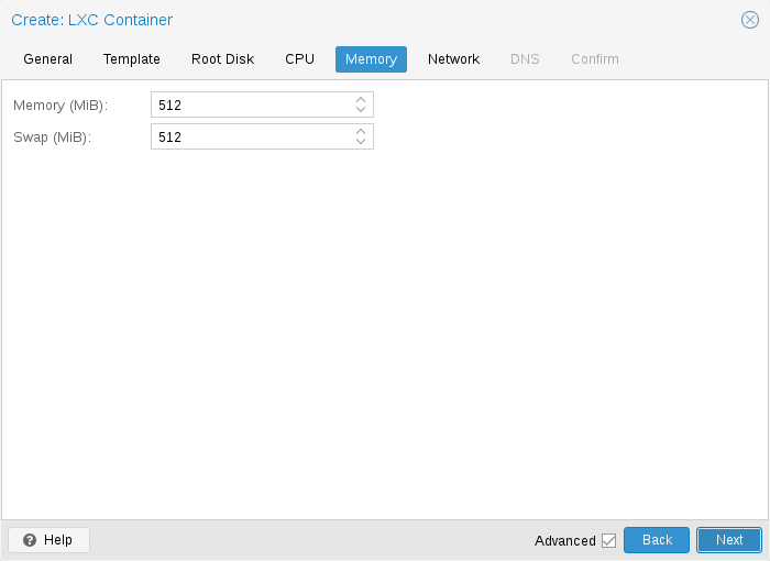
Container memory is controlled using the cgroup memory controller.
|
memory:
|
Limit overall memory usage. This corresponds to the memory.limit_in_bytes cgroup setting. |
|
swap:
|
Allows the container to use additional swap memory from the host swap space. This corresponds to the memory.memsw.limit_in_bytes cgroup setting, which is set to the sum of both value (memory + swap). |
11.4.4. Mount Points
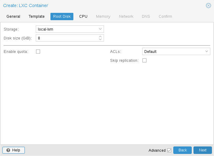
The root mount point is configured with the rootfs property. You can configure up to 256 additional mount points. The corresponding options are called mp0 to mp255. They can contain the following settings:
- rootfs: [volume=]<volume> [,acl=<1|0>] [,mountoptions=<opt[;opt...]>] [,quota=<1|0>] [,replicate=<1|0>] [,ro=<1|0>] [,shared=<1|0>] [,size=<DiskSize>]
-
Use volume as container root. See below for a detailed description of all options.
- mp[n]: [volume=]<volume> ,mp=<Path> [,acl=<1|0>] [,backup=<1|0>] [,mountoptions=<opt[;opt...]>] [,quota=<1|0>] [,replicate=<1|0>] [,ro=<1|0>] [,shared=<1|0>] [,size=<DiskSize>]
-
Use volume as container mount point. Use the special syntax STORAGE_ID:SIZE_IN_GiB to allocate a new volume.
- acl=<boolean>
-
Explicitly enable or disable ACL support.
- backup=<boolean>
-
Whether to include the mount point in backups (only used for volume mount points).
- mountoptions=<opt[;opt...]>
-
Extra mount options for rootfs/mps.
- mp=<Path>
-
Path to the mount point as seen from inside the container.
Must not contain any symlinks for security reasons. - quota=<boolean>
-
Enable user quotas inside the container (not supported with zfs subvolumes)
- replicate=<boolean> (default = 1)
-
Will include this volume to a storage replica job.
- ro=<boolean>
-
Read-only mount point
- shared=<boolean> (default = 0)
-
Mark this non-volume mount point as available on all nodes.
This option does not share the mount point automatically, it assumes it is shared already! - size=<DiskSize>
-
Volume size (read only value).
- volume=<volume>
-
Volume, device or directory to mount into the container.
Currently there are three types of mount points: storage backed mount points, bind mounts, and device mounts.
rootfs: thin1:base-100-disk-1,size=8G
Storage Backed Mount Points
Storage backed mount points are managed by the Proxmox VE storage subsystem and come in three different flavors:
-
Image based: these are raw images containing a single ext4 formatted file system.
-
ZFS subvolumes: these are technically bind mounts, but with managed storage, and thus allow resizing and snapshotting.
-
Directories: passing size=0 triggers a special case where instead of a raw image a directory is created.
|
|
The special option syntax STORAGE_ID:SIZE_IN_GB for storage backed mount point volumes will automatically allocate a volume of the specified size on the specified storage. For example, calling |
pct set 100 -mp0 thin1:10,mp=/path/in/container
will allocate a 10GB volume on the storage thin1 and replace the volume ID place holder 10 with the allocated volume ID, and setup the moutpoint in the container at /path/in/container
Bind Mount Points
Bind mounts allow you to access arbitrary directories from your Proxmox VE host inside a container. Some potential use cases are:
-
Accessing your home directory in the guest
-
Accessing an USB device directory in the guest
-
Accessing an NFS mount from the host in the guest
Bind mounts are considered to not be managed by the storage subsystem, so you cannot make snapshots or deal with quotas from inside the container. With unprivileged containers you might run into permission problems caused by the user mapping and cannot use ACLs.
|
|
The contents of bind mount points are not backed up when using vzdump. |
|
|
For security reasons, bind mounts should only be established using source directories especially reserved for this purpose, e.g., a directory hierarchy under /mnt/bindmounts. Never bind mount system directories like /, /var or /etc into a container - this poses a great security risk. |
|
|
The bind mount source path must not contain any symlinks. |
For example, to make the directory /mnt/bindmounts/shared accessible in the container with ID 100 under the path /shared, add a configuration line such as:
mp0: /mnt/bindmounts/shared,mp=/shared
into /etc/pve/lxc/100.conf.
Or alternatively use the pct tool:
pct set 100 -mp0 /mnt/bindmounts/shared,mp=/shared
to achieve the same result.
Device Mount Points
Device mount points allow to mount block devices of the host directly into the container. Similar to bind mounts, device mounts are not managed by Proxmox VE’s storage subsystem, but the quota and acl options will be honored.
|
|
Device mount points should only be used under special circumstances. In most cases a storage backed mount point offers the same performance and a lot more features. |
|
|
The contents of device mount points are not backed up when using vzdump. |
11.4.5. Network
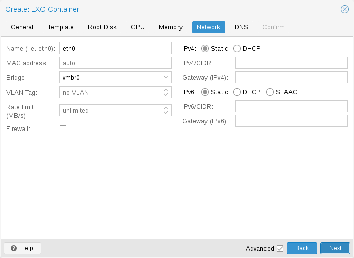
You can configure up to 10 network interfaces for a single container. The corresponding options are called net0 to net9, and they can contain the following setting:
- net[n]: name=<string> [,bridge=<bridge>] [,firewall=<1|0>] [,gw=<GatewayIPv4>] [,gw6=<GatewayIPv6>] [,hwaddr=<XX:XX:XX:XX:XX:XX>] [,ip=<(IPv4/CIDR|dhcp|manual)>] [,ip6=<(IPv6/CIDR|auto|dhcp|manual)>] [,link_down=<1|0>] [,mtu=<integer>] [,rate=<mbps>] [,tag=<integer>] [,trunks=<vlanid[;vlanid...]>] [,type=<veth>]
-
Specifies network interfaces for the container.
- bridge=<bridge>
-
Bridge to attach the network device to.
- firewall=<boolean>
-
Controls whether this interface’s firewall rules should be used.
- gw=<GatewayIPv4>
-
Default gateway for IPv4 traffic.
- gw6=<GatewayIPv6>
-
Default gateway for IPv6 traffic.
- hwaddr=<XX:XX:XX:XX:XX:XX>
-
A common MAC address with the I/G (Individual/Group) bit not set.
- ip=<(IPv4/CIDR|dhcp|manual)>
-
IPv4 address in CIDR format.
- ip6=<(IPv6/CIDR|auto|dhcp|manual)>
-
IPv6 address in CIDR format.
- link_down=<boolean>
-
Whether this interface should be disconnected (like pulling the plug).
- mtu=<integer> (64 - 65535)
-
Maximum transfer unit of the interface. (lxc.network.mtu)
- name=<string>
-
Name of the network device as seen from inside the container. (lxc.network.name)
- rate=<mbps>
-
Apply rate limiting to the interface
- tag=<integer> (1 - 4094)
-
VLAN tag for this interface.
- trunks=<vlanid[;vlanid...]>
-
VLAN ids to pass through the interface
- type=<veth>
-
Network interface type.
11.4.6. Automatic Start and Shutdown of Containers
To automatically start a container when the host system boots, select the option Start at boot in the Options panel of the container in the web interface or run the following command:
# pct set CTID -onboot 1
If you want to fine tune the boot order of your containers, you can use the following parameters:
-
Start/Shutdown order: Defines the start order priority. For example, set it to 1 if you want the CT to be the first to be started. (We use the reverse startup order for shutdown, so a container with a start order of 1 would be the last to be shut down)
-
Startup delay: Defines the interval between this container start and subsequent containers starts. For example, set it to 240 if you want to wait 240 seconds before starting other containers.
-
Shutdown timeout: Defines the duration in seconds Proxmox VE should wait for the container to be offline after issuing a shutdown command. By default this value is set to 60, which means that Proxmox VE will issue a shutdown request, wait 60s for the machine to be offline, and if after 60s the machine is still online will notify that the shutdown action failed.
Please note that containers without a Start/Shutdown order parameter will always start after those where the parameter is set, and this parameter only makes sense between the machines running locally on a host, and not cluster-wide.
If you require a delay between the host boot and the booting of the first container, see the section on Proxmox VE Node Management.
11.4.7. Hookscripts
You can add a hook script to CTs with the config property hookscript.
# pct set 100 -hookscript local:snippets/hookscript.pl
It will be called during various phases of the guests lifetime. For an example and documentation see the example script under /usr/share/pve-docs/examples/guest-example-hookscript.pl.
11.5. Security Considerations
Containers use the kernel of the host system. This exposes an attack surface for malicious users. In general, full virtual machines provide better isolation. This should be considered if containers are provided to unknown or untrusted people.
To reduce the attack surface, LXC uses many security features like AppArmor, CGroups and kernel namespaces.
11.5.1. AppArmor
AppArmor profiles are used to restrict access to possibly dangerous actions. Some system calls, i.e. mount, are prohibited from execution.
To trace AppArmor activity, use:
# dmesg | grep apparmor
Although it is not recommended, AppArmor can be disabled for a container. This brings security risks with it. Some syscalls can lead to privilege escalation when executed within a container if the system is misconfigured or if a LXC or Linux Kernel vulnerability exists.
To disable AppArmor for a container, add the following line to the container configuration file located at /etc/pve/lxc/CTID.conf:
lxc.apparmor.profile = unconfined
|
|
Please note that this is not recommended for production use. |
11.5.2. Control Groups (cgroup)
cgroup is a kernel mechanism used to hierarchically organize processes and distribute system resources.
The main resources controlled via cgroups are CPU time, memory and swap limits, and access to device nodes. cgroups are also used to "freeze" a container before taking snapshots.
Since Proxmox VE 7.0, the default is a pure cgroupv2 environment. Previously a "hybrid" setup was used, where resource control was mainly done in cgroupv1 with an additional cgroupv2 controller which could take over some subsystems via the cgroup_no_v1 kernel command-line parameter. (See the kernel parameter documentation for details.)
CGroup Version Compatibility
The main difference between pure cgroupv2 and the old hybrid environments regarding Proxmox VE is that with cgroupv2 memory and swap are now controlled independently. The memory and swap settings for containers can map directly to these values, whereas previously only the memory limit and the limit of the sum of memory and swap could be limited.
Another important difference is that the devices controller is configured in a completely different way. Because of this, file system quotas are currently not supported in a pure cgroupv2 environment.
cgroupv2 support by the container’s OS is needed to run in a pure cgroupv2
environment. Containers running systemd version 231 or newer support
cgroupv2
[this includes all newest major versions of container
templates shipped by Proxmox VE]
, as do containers not using systemd as init
system
[for example Alpine Linux]
.
|
|
CentOS 7 and Ubuntu 16.10 are two prominent Linux distributions releases, which have a systemd version that is too old to run in a cgroupv2 environment, you can either
|
Changing CGroup Version
|
|
If file system quotas are not required and all containers support cgroupv2, it is recommended to stick to the new default. |
To switch back to the previous version the following kernel command-line parameter can be used:
systemd.unified_cgroup_hierarchy=0
See this section on editing the kernel boot command line on where to add the parameter.
11.6. Guest Operating System Configuration
Proxmox VE tries to detect the Linux distribution in the container, and modifies some files. Here is a short list of things done at container startup:
- set /etc/hostname
-
to set the container name
- modify /etc/hosts
-
to allow lookup of the local hostname
- network setup
-
pass the complete network setup to the container
- configure DNS
-
pass information about DNS servers
- adapt the init system
-
for example, fix the number of spawned getty processes
- set the root password
-
when creating a new container
- rewrite ssh_host_keys
-
so that each container has unique keys
- randomize crontab
-
so that cron does not start at the same time on all containers
Changes made by Proxmox VE are enclosed by comment markers:
# --- BEGIN PVE ---
<data>
# --- END PVE ---
Those markers will be inserted at a reasonable location in the file. If such a section already exists, it will be updated in place and will not be moved.
Modification of a file can be prevented by adding a .pve-ignore. file for it. For instance, if the file /etc/.pve-ignore.hosts exists then the /etc/hosts file will not be touched. This can be a simple empty file created via:
# touch /etc/.pve-ignore.hosts
Most modifications are OS dependent, so they differ between different distributions and versions. You can completely disable modifications by manually setting the ostype to unmanaged.
OS type detection is done by testing for certain files inside the
container. Proxmox VE first checks the /etc/os-release file
[/etc/os-release replaces the multitude of per-distribution
release files https://manpages.debian.org/stable/systemd/os-release.5.en.html]
.
If that file is not present, or it does not contain a clearly recognizable
distribution identifier the following distribution specific release files are
checked.
- Ubuntu
-
inspect /etc/lsb-release (DISTRIB_ID=Ubuntu)
- Debian
-
test /etc/debian_version
- Fedora
-
test /etc/fedora-release
- RedHat or CentOS
-
test /etc/redhat-release
- ArchLinux
-
test /etc/arch-release
- Alpine
-
test /etc/alpine-release
- Gentoo
-
test /etc/gentoo-release
|
|
Container start fails if the configured ostype differs from the auto detected type. |
11.7. Container Storage
The Proxmox VE LXC container storage model is more flexible than traditional container storage models. A container can have multiple mount points. This makes it possible to use the best suited storage for each application.
For example the root file system of the container can be on slow and cheap storage while the database can be on fast and distributed storage via a second mount point. See section Mount Points for further details.
Any storage type supported by the Proxmox VE storage library can be used. This means that containers can be stored on local (for example lvm, zfs or directory), shared external (like iSCSI, NFS) or even distributed storage systems like Ceph. Advanced storage features like snapshots or clones can be used if the underlying storage supports them. The vzdump backup tool can use snapshots to provide consistent container backups.
Furthermore, local devices or local directories can be mounted directly using bind mounts. This gives access to local resources inside a container with practically zero overhead. Bind mounts can be used as an easy way to share data between containers.
11.7.1. FUSE Mounts
|
|
Because of existing issues in the Linux kernel’s freezer subsystem the usage of FUSE mounts inside a container is strongly advised against, as containers need to be frozen for suspend or snapshot mode backups. |
If FUSE mounts cannot be replaced by other mounting mechanisms or storage technologies, it is possible to establish the FUSE mount on the Proxmox host and use a bind mount point to make it accessible inside the container.
11.7.2. Using Quotas Inside Containers
Quotas allow to set limits inside a container for the amount of disk space that each user can use.
|
|
This currently requires the use of legacy cgroups. |
|
|
This only works on ext4 image based storage types and currently only works with privileged containers. |
Activating the quota option causes the following mount options to be used for a mount point: usrjquota=aquota.user,grpjquota=aquota.group,jqfmt=vfsv0
This allows quotas to be used like on any other system. You can initialize the /aquota.user and /aquota.group files by running:
# quotacheck -cmug /
# quotaon /
Then edit the quotas using the edquota command. Refer to the documentation of the distribution running inside the container for details.
|
|
You need to run the above commands for every mount point by passing the mount point’s path instead of just /. |
11.7.3. Using ACLs Inside Containers
The standard Posix Access Control Lists are also available inside containers. ACLs allow you to set more detailed file ownership than the traditional user/group/others model.
11.7.4. Backup of Container mount points
To include a mount point in backups, enable the backup option for it in the container configuration. For an existing mount point mp0
mp0: guests:subvol-100-disk-1,mp=/root/files,size=8G
add backup=1 to enable it.
mp0: guests:subvol-100-disk-1,mp=/root/files,size=8G,backup=1
|
|
When creating a new mount point in the GUI, this option is enabled by default. |
To disable backups for a mount point, add backup=0 in the way described above, or uncheck the Backup checkbox on the GUI.
11.7.5. Replication of Containers mount points
By default, additional mount points are replicated when the Root Disk is replicated. If you want the Proxmox VE storage replication mechanism to skip a mount point, you can set the Skip replication option for that mount point. As of Proxmox VE 5.0, replication requires a storage of type zfspool. Adding a mount point to a different type of storage when the container has replication configured requires to have Skip replication enabled for that mount point.
11.8. Backup and Restore
11.8.1. Container Backup
It is possible to use the vzdump tool for container backup. Please refer to the vzdump manual page for details.
11.8.2. Restoring Container Backups
Restoring container backups made with vzdump is possible using the pct restore command. By default, pct restore will attempt to restore as much of the backed up container configuration as possible. It is possible to override the backed up configuration by manually setting container options on the command line (see the pct manual page for details).
|
|
pvesm extractconfig can be used to view the backed up configuration contained in a vzdump archive. |
There are two basic restore modes, only differing by their handling of mount points:
“Simple” Restore Mode
If neither the rootfs parameter nor any of the optional mpX parameters are explicitly set, the mount point configuration from the backed up configuration file is restored using the following steps:
-
Extract mount points and their options from backup
-
Create volumes for storage backed mount points on the storage provided with the storage parameter (default: local).
-
Extract files from backup archive
-
Add bind and device mount points to restored configuration (limited to root user)
|
|
Since bind and device mount points are never backed up, no files are restored in the last step, but only the configuration options. The assumption is that such mount points are either backed up with another mechanism (e.g., NFS space that is bind mounted into many containers), or not intended to be backed up at all. |
This simple mode is also used by the container restore operations in the web interface.
“Advanced” Restore Mode
By setting the rootfs parameter (and optionally, any combination of mpX parameters), the pct restore command is automatically switched into an advanced mode. This advanced mode completely ignores the rootfs and mpX configuration options contained in the backup archive, and instead only uses the options explicitly provided as parameters.
This mode allows flexible configuration of mount point settings at restore time, for example:
-
Set target storages, volume sizes and other options for each mount point individually
-
Redistribute backed up files according to new mount point scheme
-
Restore to device and/or bind mount points (limited to root user)
11.9. Managing Containers with pct
The “Proxmox Container Toolkit” (pct) is the command-line tool to manage Proxmox VE containers. It enables you to create or destroy containers, as well as control the container execution (start, stop, reboot, migrate, etc.). It can be used to set parameters in the config file of a container, for example the network configuration or memory limits.
11.9.1. CLI Usage Examples
Create a container based on a Debian template (provided you have already downloaded the template via the web interface)
# pct create 100 /var/lib/vz/template/cache/debian-10.0-standard_10.0-1_amd64.tar.gz
Start container 100
# pct start 100
Start a login session via getty
# pct console 100
Enter the LXC namespace and run a shell as root user
# pct enter 100
Display the configuration
# pct config 100
Add a network interface called eth0, bridged to the host bridge vmbr0, set the address and gateway, while it’s running
# pct set 100 -net0 name=eth0,bridge=vmbr0,ip=192.168.15.147/24,gw=192.168.15.1
Reduce the memory of the container to 512MB
# pct set 100 -memory 512
Destroying a container always removes it from Access Control Lists and it always removes the firewall configuration of the container. You have to activate --purge, if you want to additionally remove the container from replication jobs, backup jobs and HA resource configurations.
# pct destroy 100 --purge
Move a mount point volume to a different storage.
# pct move-volume 100 mp0 other-storage
Reassign a volume to a different CT. This will remove the volume mp0 from the source CT and attaches it as mp1 to the target CT. In the background the volume is being renamed so that the name matches the new owner.
# pct move-volume 100 mp0 --target-vmid 200 --target-volume mp1
11.9.2. Obtaining Debugging Logs
In case pct start is unable to start a specific container, it might be helpful to collect debugging output by passing the --debug flag (replace CTID with the container’s CTID):
# pct start CTID --debug
Alternatively, you can use the following lxc-start command, which will save the debug log to the file specified by the -o output option:
# lxc-start -n CTID -F -l DEBUG -o /tmp/lxc-CTID.log
This command will attempt to start the container in foreground mode, to stop the container run pct shutdown CTID or pct stop CTID in a second terminal.
The collected debug log is written to /tmp/lxc-CTID.log.
|
|
If you have changed the container’s configuration since the last start attempt with pct start, you need to run pct start at least once to also update the configuration used by lxc-start. |
11.10. Migration
If you have a cluster, you can migrate your Containers with
# pct migrate <ctid> <target>
This works as long as your Container is offline. If it has local volumes or mount points defined, the migration will copy the content over the network to the target host if the same storage is defined there.
Running containers cannot live-migrated due to technical limitations. You can do a restart migration, which shuts down, moves and then starts a container again on the target node. As containers are very lightweight, this results normally only in a downtime of some hundreds of milliseconds.
A restart migration can be done through the web interface or by using the --restart flag with the pct migrate command.
A restart migration will shut down the Container and kill it after the specified timeout (the default is 180 seconds). Then it will migrate the Container like an offline migration and when finished, it starts the Container on the target node.
11.11. Configuration
The /etc/pve/lxc/<CTID>.conf file stores container configuration, where <CTID> is the numeric ID of the given container. Like all other files stored inside /etc/pve/, they get automatically replicated to all other cluster nodes.
|
|
CTIDs < 100 are reserved for internal purposes, and CTIDs need to be unique cluster wide. |
ostype: debian
arch: amd64
hostname: www
memory: 512
swap: 512
net0: bridge=vmbr0,hwaddr=66:64:66:64:64:36,ip=dhcp,name=eth0,type=veth
rootfs: local:107/vm-107-disk-1.raw,size=7G
The configuration files are simple text files. You can edit them using a normal text editor, for example, vi or nano. This is sometimes useful to do small corrections, but keep in mind that you need to restart the container to apply such changes.
For that reason, it is usually better to use the pct command to generate and modify those files, or do the whole thing using the GUI. Our toolkit is smart enough to instantaneously apply most changes to running containers. This feature is called “hot plug”, and there is no need to restart the container in that case.
In cases where a change cannot be hot-plugged, it will be registered as a pending change (shown in red color in the GUI). They will only be applied after rebooting the container.
11.11.1. File Format
The container configuration file uses a simple colon separated key/value format. Each line has the following format:
# this is a comment
OPTION: value
Blank lines in those files are ignored, and lines starting with a # character are treated as comments and are also ignored.
It is possible to add low-level, LXC style configuration directly, for example:
lxc.init_cmd: /sbin/my_own_init
or
lxc.init_cmd = /sbin/my_own_init
The settings are passed directly to the LXC low-level tools.
11.11.2. Snapshots
When you create a snapshot, pct stores the configuration at snapshot time into a separate snapshot section within the same configuration file. For example, after creating a snapshot called “testsnapshot”, your configuration file will look like this:
memory: 512
swap: 512
parent: testsnaphot
...

[testsnaphot]
memory: 512
swap: 512
snaptime: 1457170803
...
There are a few snapshot related properties like parent and snaptime. The parent property is used to store the parent/child relationship between snapshots. snaptime is the snapshot creation time stamp (Unix epoch).
11.11.3. Options
- arch: <amd64 | arm64 | armhf | i386 | riscv32 | riscv64> (default = amd64)
-
OS architecture type.
- cmode: <console | shell | tty> (default = tty)
-
Console mode. By default, the console command tries to open a connection to one of the available tty devices. By setting cmode to console it tries to attach to /dev/console instead. If you set cmode to shell, it simply invokes a shell inside the container (no login).
- console: <boolean> (default = 1)
-
Attach a console device (/dev/console) to the container.
- cores: <integer> (1 - 8192)
-
The number of cores assigned to the container. A container can use all available cores by default.
- cpulimit: <number> (0 - 8192) (default = 0)
-
Limit of CPU usage.
If the computer has 2 CPUs, it has a total of 2 CPU time. Value 0 indicates no CPU limit. - cpuunits: <integer> (0 - 500000) (default = cgroup v1: 1024, cgroup v2: 100)
-
CPU weight for a container. Argument is used in the kernel fair scheduler. The larger the number is, the more CPU time this container gets. Number is relative to the weights of all the other running guests.
- debug: <boolean> (default = 0)
-
Try to be more verbose. For now this only enables debug log-level on start.
- description: <string>
-
Description for the Container. Shown in the web-interface CT’s summary. This is saved as comment inside the configuration file.
- dev[n]: [[path=]<Path>] [,gid=<integer>] [,mode=<Octal access mode>] [,uid=<integer>]
-
Device to pass through to the container
- gid=<integer> (0 - N)
-
Group ID to be assigned to the device node
- mode=<Octal access mode>
-
Access mode to be set on the device node
- path=<Path>
-
Path to the device to pass through to the container
- uid=<integer> (0 - N)
-
User ID to be assigned to the device node
- features: [force_rw_sys=<1|0>] [,fuse=<1|0>] [,keyctl=<1|0>] [,mknod=<1|0>] [,mount=<fstype;fstype;...>] [,nesting=<1|0>]
-
Allow containers access to advanced features.
- force_rw_sys=<boolean> (default = 0)
-
Mount /sys in unprivileged containers as rw instead of mixed. This can break networking under newer (>= v245) systemd-network use.
- fuse=<boolean> (default = 0)
-
Allow using fuse file systems in a container. Note that interactions between fuse and the freezer cgroup can potentially cause I/O deadlocks.
- keyctl=<boolean> (default = 0)
-
For unprivileged containers only: Allow the use of the keyctl() system call. This is required to use docker inside a container. By default unprivileged containers will see this system call as non-existent. This is mostly a workaround for systemd-networkd, as it will treat it as a fatal error when some keyctl() operations are denied by the kernel due to lacking permissions. Essentially, you can choose between running systemd-networkd or docker.
- mknod=<boolean> (default = 0)
-
Allow unprivileged containers to use mknod() to add certain device nodes. This requires a kernel with seccomp trap to user space support (5.3 or newer). This is experimental.
- mount=<fstype;fstype;...>
-
Allow mounting file systems of specific types. This should be a list of file system types as used with the mount command. Note that this can have negative effects on the container’s security. With access to a loop device, mounting a file can circumvent the mknod permission of the devices cgroup, mounting an NFS file system can block the host’s I/O completely and prevent it from rebooting, etc.
- nesting=<boolean> (default = 0)
-
Allow nesting. Best used with unprivileged containers with additional id mapping. Note that this will expose procfs and sysfs contents of the host to the guest.
- hookscript: <string>
-
Script that will be exectued during various steps in the containers lifetime.
- hostname: <string>
-
Set a host name for the container.
- lock: <backup | create | destroyed | disk | fstrim | migrate | mounted | rollback | snapshot | snapshot-delete>
-
Lock/unlock the container.
- memory: <integer> (16 - N) (default = 512)
-
Amount of RAM for the container in MB.
- mp[n]: [volume=]<volume> ,mp=<Path> [,acl=<1|0>] [,backup=<1|0>] [,mountoptions=<opt[;opt...]>] [,quota=<1|0>] [,replicate=<1|0>] [,ro=<1|0>] [,shared=<1|0>] [,size=<DiskSize>]
-
Use volume as container mount point. Use the special syntax STORAGE_ID:SIZE_IN_GiB to allocate a new volume.
- acl=<boolean>
-
Explicitly enable or disable ACL support.
- backup=<boolean>
-
Whether to include the mount point in backups (only used for volume mount points).
- mountoptions=<opt[;opt...]>
-
Extra mount options for rootfs/mps.
- mp=<Path>
-
Path to the mount point as seen from inside the container.
Must not contain any symlinks for security reasons. - quota=<boolean>
-
Enable user quotas inside the container (not supported with zfs subvolumes)
- replicate=<boolean> (default = 1)
-
Will include this volume to a storage replica job.
- ro=<boolean>
-
Read-only mount point
- shared=<boolean> (default = 0)
-
Mark this non-volume mount point as available on all nodes.
This option does not share the mount point automatically, it assumes it is shared already! - size=<DiskSize>
-
Volume size (read only value).
- volume=<volume>
-
Volume, device or directory to mount into the container.
- nameserver: <string>
-
Sets DNS server IP address for a container. Create will automatically use the setting from the host if you neither set searchdomain nor nameserver.
- net[n]: name=<string> [,bridge=<bridge>] [,firewall=<1|0>] [,gw=<GatewayIPv4>] [,gw6=<GatewayIPv6>] [,hwaddr=<XX:XX:XX:XX:XX:XX>] [,ip=<(IPv4/CIDR|dhcp|manual)>] [,ip6=<(IPv6/CIDR|auto|dhcp|manual)>] [,link_down=<1|0>] [,mtu=<integer>] [,rate=<mbps>] [,tag=<integer>] [,trunks=<vlanid[;vlanid...]>] [,type=<veth>]
-
Specifies network interfaces for the container.
- bridge=<bridge>
-
Bridge to attach the network device to.
- firewall=<boolean>
-
Controls whether this interface’s firewall rules should be used.
- gw=<GatewayIPv4>
-
Default gateway for IPv4 traffic.
- gw6=<GatewayIPv6>
-
Default gateway for IPv6 traffic.
- hwaddr=<XX:XX:XX:XX:XX:XX>
-
A common MAC address with the I/G (Individual/Group) bit not set.
- ip=<(IPv4/CIDR|dhcp|manual)>
-
IPv4 address in CIDR format.
- ip6=<(IPv6/CIDR|auto|dhcp|manual)>
-
IPv6 address in CIDR format.
- link_down=<boolean>
-
Whether this interface should be disconnected (like pulling the plug).
- mtu=<integer> (64 - 65535)
-
Maximum transfer unit of the interface. (lxc.network.mtu)
- name=<string>
-
Name of the network device as seen from inside the container. (lxc.network.name)
- rate=<mbps>
-
Apply rate limiting to the interface
- tag=<integer> (1 - 4094)
-
VLAN tag for this interface.
- trunks=<vlanid[;vlanid...]>
-
VLAN ids to pass through the interface
- type=<veth>
-
Network interface type.
- onboot: <boolean> (default = 0)
-
Specifies whether a container will be started during system bootup.
- ostype: <alpine | archlinux | centos | debian | devuan | fedora | gentoo | nixos | opensuse | ubuntu | unmanaged>
-
OS type. This is used to setup configuration inside the container, and corresponds to lxc setup scripts in /usr/share/lxc/config/<ostype>.common.conf. Value unmanaged can be used to skip and OS specific setup.
- protection: <boolean> (default = 0)
-
Sets the protection flag of the container. This will prevent the CT or CT’s disk remove/update operation.
- rootfs: [volume=]<volume> [,acl=<1|0>] [,mountoptions=<opt[;opt...]>] [,quota=<1|0>] [,replicate=<1|0>] [,ro=<1|0>] [,shared=<1|0>] [,size=<DiskSize>]
-
Use volume as container root.
- acl=<boolean>
-
Explicitly enable or disable ACL support.
- mountoptions=<opt[;opt...]>
-
Extra mount options for rootfs/mps.
- quota=<boolean>
-
Enable user quotas inside the container (not supported with zfs subvolumes)
- replicate=<boolean> (default = 1)
-
Will include this volume to a storage replica job.
- ro=<boolean>
-
Read-only mount point
- shared=<boolean> (default = 0)
-
Mark this non-volume mount point as available on all nodes.
This option does not share the mount point automatically, it assumes it is shared already! - size=<DiskSize>
-
Volume size (read only value).
- volume=<volume>
-
Volume, device or directory to mount into the container.
- searchdomain: <string>
-
Sets DNS search domains for a container. Create will automatically use the setting from the host if you neither set searchdomain nor nameserver.
- startup: `[[order=]\d+] [,up=\d+] [,down=\d+] `
-
Startup and shutdown behavior. Order is a non-negative number defining the general startup order. Shutdown in done with reverse ordering. Additionally you can set the up or down delay in seconds, which specifies a delay to wait before the next VM is started or stopped.
- swap: <integer> (0 - N) (default = 512)
-
Amount of SWAP for the container in MB.
- tags: <string>
-
Tags of the Container. This is only meta information.
- template: <boolean> (default = 0)
-
Enable/disable Template.
- timezone: <string>
-
Time zone to use in the container. If option isn’t set, then nothing will be done. Can be set to host to match the host time zone, or an arbitrary time zone option from /usr/share/zoneinfo/zone.tab
- tty: <integer> (0 - 6) (default = 2)
-
Specify the number of tty available to the container
- unprivileged: <boolean> (default = 0)
-
Makes the container run as unprivileged user. (Should not be modified manually.)
- unused[n]: [volume=]<volume>
-
Reference to unused volumes. This is used internally, and should not be modified manually.
- volume=<volume>
-
The volume that is not used currently.
11.12. Locks
Container migrations, snapshots and backups (vzdump) set a lock to prevent incompatible concurrent actions on the affected container. Sometimes you need to remove such a lock manually (e.g., after a power failure).
# pct unlock <CTID>
|
|
Only do this if you are sure the action which set the lock is no longer running. |
12. Software-Defined Network
The Software-Defined Network (SDN) feature in Proxmox VE enables the creation of virtual zones and networks (VNets). This functionality simplifies advanced networking configurations and multitenancy setup.
12.1. Introduction
The Proxmox VE SDN allows for separation and fine-grained control of virtual guest networks, using flexible, software-controlled configurations.
Separation is managed through zones, virtual networks (VNets), and subnets. A zone is its own virtually separated network area. A VNet is a virtual network that belongs to a zone. A subnet is an IP range inside a VNet.
Depending on the type of the zone, the network behaves differently and offers specific features, advantages, and limitations.
Use cases for SDN range from an isolated private network on each individual node to complex overlay networks across multiple PVE clusters on different locations.
After configuring an VNet in the cluster-wide datacenter SDN administration interface, it is available as a common Linux bridge, locally on each node, to be assigned to VMs and Containers.
12.2. Support Status
12.2.1. History
The Proxmox VE SDN stack has been available as an experimental feature since 2019 and has been continuously improved and tested by many developers and users. With its integration into the web interface in Proxmox VE 6.2, a significant milestone towards broader integration was achieved. During the Proxmox VE 7 release cycle, numerous improvements and features were added. Based on user feedback, it became apparent that the fundamental design choices and their implementation were quite sound and stable. Consequently, labeling it as ‘experimental’ did not do justice to the state of the SDN stack. For Proxmox VE 8, a decision was made to lay the groundwork for full integration of the SDN feature by elevating the management of networks and interfaces to a core component in the Proxmox VE access control stack. In Proxmox VE 8.1, two major milestones were achieved: firstly, DHCP integration was added to the IP address management (IPAM) feature, and secondly, the SDN integration is now installed by default.
12.2.2. Current Status
The current support status for the various layers of our SDN installation is as follows:
-
Core SDN, which includes VNet management and its integration with the Proxmox VE stack, is fully supported.
-
IPAM, including DHCP management for virtual guests, is in tech preview.
-
Complex routing via FRRouting and controller integration are in tech preview.
12.3. Installation
12.3.1. SDN Core
Since Proxmox VE 8.1 the core Software-Defined Network (SDN) packages are installed by default.
If you upgrade from an older version, you need to install the libpve-network-perl package on every node:
apt update
apt install libpve-network-perl
|
|
Proxmox VE version 7.0 and above have the ifupdown2 package installed by default. If you originally installed your system with an older version, you need to explicitly install the ifupdown2 package. |
After installation, you need to ensure that the following line is present at the end of the /etc/network/interfaces configuration file on all nodes, so that the SDN configuration gets included and activated.
source /etc/network/interfaces.d/*
12.3.2. DHCP IPAM
The DHCP integration into the built-in PVE IP Address Management stack currently uses dnsmasq for giving out DHCP leases. This is currently opt-in.
To use that feature you need to install the dnsmasq package on every node:
apt update
apt install dnsmasq
# disable default instance
systemctl disable --now dnsmasq
12.3.3. FRRouting
The Proxmox VE SDN stack uses the FRRouting project for advanced setups. This is currently opt-in.
To use the SDN routing integration you need to install the frr-pythontools package on all nodes:
apt update
apt install frr-pythontools
12.4. Configuration Overview
Configuration is done at the web UI at datacenter level, separated into the following sections:
The Options category allows adding and managing additional services to be used in your SDN setup.
-
Controllers: For controlling layer 3 routing in complex setups
-
DHCP: Define a DHCP server for a zone that automatically allocates IPs for guests in the IPAM and leases them to the guests via DHCP.
-
IPAM: Enables external for IP address management for guests
-
DNS: Define a DNS server integration for registering virtual guests' hostname and IP addresses
12.5. Technology & Configuration
The Proxmox VE Software-Defined Network implementation uses standard Linux networking as much as possible. The reason for this is that modern Linux networking provides almost all needs for a feature full SDN implementation and avoids adding external dependencies and reduces the overall amount of components that can break.
The Proxmox VE SDN configurations are located in /etc/pve/sdn, which is shared with all other cluster nodes through the Proxmox VE configuration file system. Those configurations get translated to the respective configuration formats of the tools that manage the underlying network stack (for example ifupdown2 or frr).
New changes are not immediately applied but recorded as pending first. You can then apply a set of different changes all at once in the main SDN overview panel on the web interface. This system allows to roll-out various changes as single atomic one.
The SDN tracks the rolled-out state through the .running-config and .version files located in /etc/pve/sdn.
12.6. Zones
A zone defines a virtually separated network. Zones are restricted to specific nodes and assigned permissions, in order to restrict users to a certain zone and its contained VNets.
Different technologies can be used for separation:
-
Simple: Isolated Bridge. A simple layer 3 routing bridge (NAT)
-
VLAN: Virtual LANs are the classic method of subdividing a LAN
-
QinQ: Stacked VLAN (formally known as IEEE 802.1ad)
-
VXLAN: Layer 2 VXLAN network via a UDP tunnel
-
EVPN (BGP EVPN): VXLAN with BGP to establish Layer 3 routing
12.6.1. Common Options
The following options are available for all zone types:
- Nodes
-
The nodes which the zone and associated VNets should be deployed on.
- IPAM
-
Use an IP Address Management (IPAM) tool to manage IPs in the zone. Optional, defaults to pve.
- DNS
-
DNS API server. Optional.
- ReverseDNS
-
Reverse DNS API server. Optional.
- DNSZone
-
DNS domain name. Used to register hostnames, such as <hostname>.<domain>. The DNS zone must already exist on the DNS server. Optional.
12.6.2. Simple Zones
This is the simplest plugin. It will create an isolated VNet bridge. This bridge is not linked to a physical interface, and VM traffic is only local on each the node. It can be used in NAT or routed setups.
12.6.3. VLAN Zones
The VLAN plugin uses an existing local Linux or OVS bridge to connect to the node’s physical interface. It uses VLAN tagging defined in the VNet to isolate the network segments. This allows connectivity of VMs between different nodes.
VLAN zone configuration options:
- Bridge
-
The local bridge or OVS switch, already configured on each node that allows node-to-node connection.
12.6.4. QinQ Zones
QinQ also known as VLAN stacking, that uses multiple layers of VLAN tags for isolation. The QinQ zone defines the outer VLAN tag (the Service VLAN) whereas the inner VLAN tag is defined by the VNet.
|
|
Your physical network switches must support stacked VLANs for this configuration. |
QinQ zone configuration options:
- Bridge
-
A local, VLAN-aware bridge that is already configured on each local node
- Service VLAN
-
The main VLAN tag of this zone
- Service VLAN Protocol
-
Allows you to choose between an 802.1q (default) or 802.1ad service VLAN type.
- MTU
-
Due to the double stacking of tags, you need 4 more bytes for QinQ VLANs. For example, you must reduce the MTU to 1496 if you physical interface MTU is 1500.
12.6.5. VXLAN Zones
The VXLAN plugin establishes a tunnel (overlay) on top of an existing network (underlay). This encapsulates layer 2 Ethernet frames within layer 4 UDP datagrams using the default destination port 4789.
You have to configure the underlay network yourself to enable UDP connectivity between all peers.
You can, for example, create a VXLAN overlay network on top of public internet, appearing to the VMs as if they share the same local Layer 2 network.
|
|
VXLAN on its own does does not provide any encryption. When joining multiple sites via VXLAN, make sure to establish a secure connection between the site, for example by using a site-to-site VPN. |
VXLAN zone configuration options:
- Peers Address List
-
A list of IP addresses of each node in the VXLAN zone. This can be external nodes reachable at this IP address. All nodes in the cluster need to be mentioned here.
- MTU
-
Because VXLAN encapsulation uses 50 bytes, the MTU needs to be 50 bytes lower than the outgoing physical interface.
12.6.6. EVPN Zones
The EVPN zone creates a routable Layer 3 network, capable of spanning across multiple clusters. This is achieved by establishing a VPN and utilizing BGP as the routing protocol.
The VNet of EVPN can have an anycast IP address and/or MAC address. The bridge IP is the same on each node, meaning a virtual guest can use this address as gateway.
Routing can work across VNets from different zones through a VRF (Virtual Routing and Forwarding) interface.
EVPN zone configuration options:
- VRF VXLAN ID
-
A VXLAN-ID used for dedicated routing interconnect between VNets. It must be different than the VXLAN-ID of the VNets.
- Controller
-
The EVPN-controller to use for this zone. (See controller plugins section).
- VNet MAC Address
-
Anycast MAC address that gets assigned to all VNets in this zone. Will be auto-generated if not defined.
- Exit Nodes
-
Nodes that shall be configured as exit gateways from the EVPN network, through the real network. The configured nodes will announce a default route in the EVPN network. Optional.
- Primary Exit Node
-
If you use multiple exit nodes, force traffic through this primary exit node, instead of load-balancing on all nodes. Optional but necessary if you want to use SNAT or if your upstream router doesn’t support ECMP.
- Exit Nodes Local Routing
-
This is a special option if you need to reach a VM/CT service from an exit node. (By default, the exit nodes only allow forwarding traffic between real network and EVPN network). Optional.
- Advertise Subnets
-
Announce the full subnet in the EVPN network. If you have silent VMs/CTs (for example, if you have multiple IPs and the anycast gateway doesn’t see traffic from theses IPs, the IP addresses won’t be able to be reached inside the EVPN network). Optional.
- Disable ARP ND Suppression
-
Don’t suppress ARP or ND (Neighbor Discovery) packets. This is required if you use floating IPs in your VMs (IP and MAC addresses are being moved between systems). Optional.
- Route-target Import
-
Allows you to import a list of external EVPN route targets. Used for cross-DC or different EVPN network interconnects. Optional.
- MTU
-
Because VXLAN encapsulation uses 50 bytes, the MTU needs to be 50 bytes less than the maximal MTU of the outgoing physical interface. Optional, defaults to 1450.
12.7. VNets
After creating a virtual network (VNet) through the SDN GUI, a local network interface with the same name is available on each node. To connect a guest to the VNet, assign the interface to the guest and set the IP address accordingly.
Depending on the zone, these options have different meanings and are explained in the respective zone section in this document.
|
|
In the current state, some options may have no effect or won’t work in certain zones. |
VNet configuration options:
- ID
-
An up to 8 character ID to identify a VNet
- Comment
-
More descriptive identifier. Assigned as an alias on the interface. Optional
- Zone
-
The associated zone for this VNet
- Tag
-
The unique VLAN or VXLAN ID
- VLAN Aware
-
Enables vlan-aware option on the interface, enabling configuration in the guest.
12.8. Subnets
A subnet define a specific IP range, described by the CIDR network address. Each VNet, can have one or more subnets.
A subnet can be used to:
-
Restrict the IP addresses you can define on a specific VNet
-
Assign routes/gateways on a VNet in layer 3 zones
-
Enable SNAT on a VNet in layer 3 zones
-
Auto assign IPs on virtual guests (VM or CT) through IPAM plugins
-
DNS registration through DNS plugins
If an IPAM server is associated with the subnet zone, the subnet prefix will be automatically registered in the IPAM.
Subnet configuration options:
- ID
-
A CIDR network address, for example 10.0.0.0/8
- Gateway
-
The IP address of the network’s default gateway. On layer 3 zones (Simple/EVPN plugins), it will be deployed on the VNet.
- SNAT
-
Enable Source NAT which allows VMs from inside a VNet to connect to the outside network by forwarding the packets to the nodes outgoing interface. On EVPN zones, forwarding is done on EVPN gateway-nodes. Optional.
- DNS Zone Prefix
-
Add a prefix to the domain registration, like <hostname>.prefix.<domain> Optional.
12.9. Controllers
Some zones implement a separated control and data plane that require an external controller to manage the VNet’s control plane.
Currently, only the EVPN zone requires an external controller.
12.9.1. EVPN Controller
The EVPN, zone requires an external controller to manage the control plane. The EVPN controller plugin configures the Free Range Routing (frr) router.
To enable the EVPN controller, you need to install frr on every node that shall participate in the EVPN zone.
apt install frr frr-pythontools
EVPN controller configuration options:
- ASN #
-
A unique BGP ASN number. It’s highly recommended to use a private ASN number (64512 – 65534, 4200000000 – 4294967294), as otherwise you could end up breaking global routing by mistake.
- Peers
-
An IP list of all nodes that are part of the EVPN zone. (could also be external nodes or route reflector servers)
12.9.2. BGP Controller
The BGP controller is not used directly by a zone. You can use it to configure FRR to manage BGP peers.
For BGP-EVPN, it can be used to define a different ASN by node, so doing EBGP. It can also be used to export EVPN routes to an external BGP peer.
|
|
By default, for a simple full mesh EVPN, you don’t need to define a BGP controller. |
BGP controller configuration options:
- Node
-
The node of this BGP controller
- ASN #
-
A unique BGP ASN number. It’s highly recommended to use a private ASN number in the range (64512 - 65534) or (4200000000 - 4294967294), as otherwise you could break global routing by mistake.
- Peer
-
A list of peer IP addresses you want to communicate with using the underlying BGP network.
- EBGP
-
If your peer’s remote-AS is different, this enables EBGP.
- Loopback Interface
-
Use a loopback or dummy interface as the source of the EVPN network (for multipath).
- ebgp-mutltihop
-
Increase the number of hops to reach peers, in case they are not directly connected or they use loopback.
- bgp-multipath-as-path-relax
-
Allow ECMP if your peers have different ASN.
12.9.3. ISIS Controller
The ISIS controller is not used directly by a zone. You can use it to configure FRR to export EVPN routes to an ISIS domain.
ISIS controller configuration options:
- Node
-
The node of this ISIS controller.
- Domain
-
A unique ISIS domain.
- Network Entity Title
-
A Unique ISIS network address that identifies this node.
- Interfaces
-
A list of physical interface(s) used by ISIS.
- Loopback
-
Use a loopback or dummy interface as the source of the EVPN network (for multipath).
12.10. IPAM
IP Address Management (IPAM) tools manage the IP addresses of clients on the network. SDN in Proxmox VE uses IPAM for example to find free IP addresses for new guests.
A single IPAM instance can be associated with one or more zones.
12.10.1. PVE IPAM Plugin
The default built-in IPAM for your Proxmox VE cluster.
You can inspect the current status of the PVE IPAM Plugin via the IPAM panel in the SDN section of the datacenter configuration. This UI can be used to create, update and delete IP mappings. This is particularly convenient in conjunction with the DHCP feature.
If you are using DHCP, you can use the IPAM panel to create or edit leases for specific VMs, which enables you to change the IPs allocated via DHCP. When editing an IP of a VM that is using DHCP you must make sure to force the guest to acquire a new DHCP leases. This can usually be done by reloading the network stack of the guest or rebooting it.
12.10.2. NetBox IPAM Plugin
NetBox is an open-source IP Address Management (IPAM) and datacenter infrastructure management (DCIM) tool.
To integrate NetBox with Proxmox VE SDN, create an API token in NetBox as described here: https://docs.netbox.dev/en/stable/integrations/rest-api/#tokens
The NetBox configuration properties are:
- URL
-
The NetBox REST API endpoint: http://yournetbox.domain.com/api
- Token
-
An API access token
12.10.3. phpIPAM Plugin
In phpIPAM you need to create an "application" and add an API token with admin privileges to the application.
The phpIPAM configuration properties are:
- URL
-
The REST-API endpoint: http://phpipam.domain.com/api/<appname>/
- Token
-
An API access token
- Section
-
An integer ID. Sections are a group of subnets in phpIPAM. Default installations use sectionid=1 for customers.
12.11. DNS
The DNS plugin in Proxmox VE SDN is used to define a DNS API server for registration of your hostname and IP address. A DNS configuration is associated with one or more zones, to provide DNS registration for all the subnet IPs configured for a zone.
12.11.1. PowerDNS Plugin
You need to enable the web server and the API in your PowerDNS config:
api=yes
api-key=arandomgeneratedstring
webserver=yes
webserver-port=8081
The PowerDNS configuration options are:
- url
-
The REST API endpoint: http://yourpowerdnserver.domain.com:8081/api/v1/servers/localhost
- key
-
An API access key
- ttl
-
The default TTL for records
12.12. DHCP
The DHCP plugin in Proxmox VE SDN can be used to automatically deploy a DHCP server for a Zone. It provides DHCP for all Subnets in a Zone that have a DHCP range configured. Currently the only available backend plugin for DHCP is the dnsmasq plugin.
The DHCP plugin works by allocating an IP in the IPAM plugin configured in the Zone when adding a new network interface to a VM/CT. You can find more information on how to configure an IPAM in the respective section of our documentation.
When the VM starts, a mapping for the MAC address and IP gets created in the DHCP plugin of the zone. When the network interfaces is removed or the VM/CT are destroyed, then the entry in the IPAM and the DHCP server are deleted as well.
|
|
Some features (adding/editing/removing IP mappings) are currently only available when using the PVE IPAM plugin. |
12.12.1. Configuration
You can enable automatic DHCP for a zone in the Web UI via the Zones panel and enabling DHCP in the advanced options of a zone.
|
|
Currently only Simple Zones have support for automatic DHCP |
After automatic DHCP has been enabled for a Zone, DHCP Ranges need to be configured for the subnets in a Zone. In order to that, go to the Vnets panel and select the Subnet for which you want to configure DHCP ranges. In the edit dialogue you can configure DHCP ranges in the respective Tab. Alternatively you can set DHCP ranges for a Subnet via the following CLI command:
pvesh set /cluster/sdn/vnets/<vnet>/subnets/<subnet>
 -dhcp-range start-address=10.0.1.100,end-address=10.0.1.200
 -dhcp-range start-address=10.0.2.100,end-address=10.0.2.200
You also need to have a gateway configured for the subnet - otherwise automatic DHCP will not work.
The DHCP plugin will then allocate IPs in the IPAM only in the configured ranges.
Do not forget to follow the installation steps for the dnsmasq DHCP plugin as well.
12.12.2. Plugins
Dnsmasq Plugin
Currently this is the only DHCP plugin and therefore the plugin that gets used when you enable DHCP for a zone.
For installation see the DHCP IPAM section.
The plugin will create a new systemd service for each zone that dnsmasq gets deployed to. The name for the service is dnsmasq@<zone>. The lifecycle of this service is managed by the DHCP plugin.
The plugin automatically generates the following configuration files in the folder /etc/dnsmasq.d/<zone>:
- 00-default.conf
-
This contains the default global configuration for a dnsmasq instance.
- 10-<zone>-<subnet_cidr>.conf
-
This file configures specific options for a subnet, such as the DNS server that should get configured via DHCP.
- 10-<zone>-<subnet_cidr>.ranges.conf
-
This file configures the DHCP ranges for the dnsmasq instance.
- ethers
-
This file contains the MAC-address and IP mappings from the IPAM plugin. In order to override those mappings, please use the respective IPAM plugin rather than editing this file, as it will get overwritten by the dnsmasq plugin.
You must not edit any of the above files, since they are managed by the DHCP plugin. In order to customize the dnsmasq configuration you can create additional files (e.g. 90-custom.conf) in the configuration folder - they will not get changed by the dnsmasq DHCP plugin.
Configuration files are read in order, so you can control the order of the configuration directives by naming your custom configuration files appropriately.
DHCP leases are stored in the file /var/lib/misc/dnsmasq.<zone>.leases.
When using the PVE IPAM plugin, you can update, create and delete DHCP leases. For more information please consult the documentation of the PVE IPAM plugin. Changing DHCP leases is currently not supported for the other IPAM plugins.
12.13. Examples
This section presents multiple configuration examples tailored for common SDN use cases. It aims to offer tangible implementations, providing additional details to enhance comprehension of the available configuration options.
12.13.1. Simple Zone Example
Simple zone networks create an isolated network for guests on a single host to connect to each other.
|
|
connection between guests are possible if all guests reside on a same host but cannot be reached on other nodes. |
-
Create a simple zone named simple.
-
Add a VNet names vnet1.
-
Create a Subnet with a gateway and the SNAT option enabled.
-
This creates a network bridge vnet1 on the node. Assign this bridge to the guests that shall join the network and configure an IP address.
The network interface configuration in two VMs may look like this which allows them to communicate via the 10.0.1.0/24 network.
allow-hotplug ens19
iface ens19 inet static
        address 10.0.1.14/24
allow-hotplug ens19
iface ens19 inet static
        address 10.0.1.15/24
12.13.2. Source NAT Example
If you want to allow outgoing connections for guests in the simple network zone the simple zone offers a Source NAT (SNAT) option.
Starting from the configuration above, Add a Subnet to the VNet vnet1, set a gateway IP and enable the SNAT option.
Subnet: 172.16.0.0/24
Gateway: 172.16.0.1
SNAT: checked
In the guests configure the static IP address inside the subnet’s IP range.
The node itself will join this network with the Gateway IP 172.16.0.1 and function as the NAT gateway for guests within the subnet range.
12.13.3. VLAN Setup Example
When VMs on different nodes need to communicate through an isolated network, the VLAN zone allows network level isolation using VLAN tags.
Create a VLAN zone named myvlanzone:
ID: myvlanzone
Bridge: vmbr0
Create a VNet named myvnet1 with VLAN tag 10 and the previously created myvlanzone.
ID: myvnet1
Zone: myvlanzone
Tag: 10
Apply the configuration through the main SDN panel, to create VNets locally on each node.
Create a Debian-based virtual machine (vm1) on node1, with a vNIC on myvnet1.
Use the following network configuration for this VM:
auto eth0
iface eth0 inet static
        address 10.0.3.100/24
Create a second virtual machine (vm2) on node2, with a vNIC on the same VNet myvnet1 as vm1.
Use the following network configuration for this VM:
auto eth0
iface eth0 inet static
        address 10.0.3.101/24
Following this, you should be able to ping between both VMs using that network.
12.13.4. QinQ Setup Example
This example configures two QinQ zones and adds two VMs to each zone to demonstrate the additional layer of VLAN tags which allows the configuration of more isolated VLANs.
A typical use case for this configuration is a hosting provider that provides an isolated network to customers for VM communication but isolates the VMs from other customers.
Create a QinQ zone named qinqzone1 with service VLAN 20
ID: qinqzone1
Bridge: vmbr0
Service VLAN: 20
Create another QinQ zone named qinqzone2 with service VLAN 30
ID: qinqzone2
Bridge: vmbr0
Service VLAN: 30
Create a VNet named myvnet1 with VLAN-ID 100 on the previously created qinqzone1 zone.
ID: qinqvnet1
Zone: qinqzone1
Tag: 100
Create a myvnet2 with VLAN-ID 100 on the qinqzone2 zone.
ID: qinqvnet2
Zone: qinqzone2
Tag: 100
Apply the configuration on the main SDN web interface panel to create VNets locally on each node.
Create four Debian-bases virtual machines (vm1, vm2, vm3, vm4) and add network interfaces to vm1 and vm2 with bridge qinqvnet1 and vm3 and vm4 with bridge qinqvnet2.
Inside the VM, configure the IP addresses of the interfaces, for example via /etc/network/interfaces:
auto eth0
iface eth0 inet static
        address 10.0.3.101/24
Configure all four VMs to have IP addresses from the 10.0.3.101 to 10.0.3.104 range.
Now you should be able to ping between the VMs vm1 and vm2, as well as between vm3 and vm4. However, neither of VMs vm1 or vm2 can ping VMs vm3 or vm4, as they are on a different zone with a different service-VLAN.
12.13.5. VXLAN Setup Example
The example assumes a cluster with three nodes, with the node IP addresses 192.168.0.1, 192.168.0.2 and 192.168.0.3.
Create a VXLAN zone named myvxlanzone and add all IPs from the nodes to the peer address list. Use the default MTU of 1450 or configure accordingly.
ID: myvxlanzone
Peers Address List: 192.168.0.1,192.168.0.2,192.168.0.3
Create a VNet named vxvnet1 using the VXLAN zone myvxlanzone created previously.
ID: vxvnet1
Zone: myvxlanzone
Tag: 100000
Apply the configuration on the main SDN web interface panel to create VNets locally on each nodes.
Create a Debian-based virtual machine (vm1) on node1, with a vNIC on vxvnet1.
Use the following network configuration for this VM (note the lower MTU).
auto eth0
iface eth0 inet static
        address 10.0.3.100/24
        mtu 1450
Create a second virtual machine (vm2) on node3, with a vNIC on the same VNet vxvnet1 as vm1.
Use the following network configuration for this VM:
auto eth0
iface eth0 inet static
        address 10.0.3.101/24
        mtu 1450
Then, you should be able to ping between between vm1 and vm2.
12.13.6. EVPN Setup Example
The example assumes a cluster with three nodes (node1, node2, node3) with IP addresses 192.168.0.1, 192.168.0.2 and 192.168.0.3.
Create an EVPN controller, using a private ASN number and the above node addresses as peers.
ID: myevpnctl
ASN#: 65000
Peers: 192.168.0.1,192.168.0.2,192.168.0.3
Create an EVPN zone named myevpnzone, assign the previously created EVPN-controller and define node1 and node2 as exit nodes.
ID: myevpnzone
VRF VXLAN Tag: 10000
Controller: myevpnctl
MTU: 1450
VNet MAC Address: 32:F4:05:FE:6C:0A
Exit Nodes: node1,node2
Create the first VNet named myvnet1 using the EVPN zone myevpnzone.
ID: myvnet1
Zone: myevpnzone
Tag: 11000
Create a subnet on myvnet1:
Subnet: 10.0.1.0/24
Gateway: 10.0.1.1
Create the second VNet named myvnet2 using the same EVPN zone myevpnzone.
ID: myvnet2
Zone: myevpnzone
Tag: 12000
Create a different subnet on myvnet2`:
Subnet: 10.0.2.0/24
Gateway: 10.0.2.1
Apply the configuration from the main SDN web interface panel to create VNets locally on each node and generate the FRR configuration.
Create a Debian-based virtual machine (vm1) on node1, with a vNIC on myvnet1.
Use the following network configuration for vm1:
auto eth0
iface eth0 inet static
        address 10.0.1.100/24
        gateway 10.0.1.1
        mtu 1450
Create a second virtual machine (vm2) on node2, with a vNIC on the other VNet myvnet2.
Use the following network configuration for vm2:
auto eth0
iface eth0 inet static
        address 10.0.2.100/24
        gateway 10.0.2.1
        mtu 1450
Now you should be able to ping vm2 from vm1, and vm1 from vm2.
If you ping an external IP from vm2 on the non-gateway node3, the packet will go to the configured myvnet2 gateway, then will be routed to the exit nodes (node1 or node2) and from there it will leave those nodes over the default gateway configured on node1 or node2.
|
|
You need to add reverse routes for the 10.0.1.0/24 and 10.0.2.0/24 networks to node1 and node2 on your external gateway, so that the public network can reply back. |
If you have configured an external BGP router, the BGP-EVPN routes (10.0.1.0/24 and 10.0.2.0/24 in this example), will be announced dynamically.
12.14. Notes
12.14.1. Multiple EVPN Exit Nodes
If you have multiple gateway nodes, you should disable the rp_filter (Strict Reverse Path Filter) option, because packets can arrive at one node but go out from another node.
Add the following to /etc/sysctl.conf:
net.ipv4.conf.default.rp_filter=0
net.ipv4.conf.all.rp_filter=0
12.14.2. VXLAN IPSEC Encryption
To add IPSEC encryption on top of a VXLAN, this example shows how to use strongswan.
You`ll need to reduce the MTU by additional 60 bytes for IPv4 or 80 bytes for IPv6 to handle encryption.
So with default real 1500 MTU, you need to use a MTU of 1370 (1370 + 80 (IPSEC) + 50 (VXLAN) == 1500).
Install strongswan on the host.
apt install strongswan
Add configuration to /etc/ipsec.conf. We only need to encrypt traffic from the VXLAN UDP port 4789.
conn %default
    ike=aes256-sha1-modp1024!  # the fastest, but reasonably secure cipher on modern HW
    esp=aes256-sha1!
    leftfirewall=yes           # this is necessary when using Proxmox VE firewall rules

conn output
    rightsubnet=%dynamic[udp/4789]
    right=%any
    type=transport
    authby=psk
    auto=route

conn input
    leftsubnet=%dynamic[udp/4789]
    type=transport
    authby=psk
    auto=route
Generate a pre-shared key with:
openssl rand -base64 128
and add the key to /etc/ipsec.secrets, so that the file contents looks like:
: PSK <generatedbase64key>
Copy the PSK and the configuration to all nodes participating in the VXLAN network.
13. Proxmox VE Firewall
Proxmox VE Firewall provides an easy way to protect your IT infrastructure. You can setup firewall rules for all hosts inside a cluster, or define rules for virtual machines and containers. Features like firewall macros, security groups, IP sets and aliases help to make that task easier.
While all configuration is stored on the cluster file system, the iptables-based firewall service runs on each cluster node, and thus provides full isolation between virtual machines. The distributed nature of this system also provides much higher bandwidth than a central firewall solution.
The firewall has full support for IPv4 and IPv6. IPv6 support is fully transparent, and we filter traffic for both protocols by default. So there is no need to maintain a different set of rules for IPv6.
13.1. Zones
The Proxmox VE firewall groups the network into the following logical zones:
- Host
-
Traffic from/to a cluster node
- VM
-
Traffic from/to a specific VM
For each zone, you can define firewall rules for incoming and/or outgoing traffic.
13.2. Configuration Files
All firewall related configuration is stored on the proxmox cluster file system. So those files are automatically distributed to all cluster nodes, and the pve-firewall service updates the underlying iptables rules automatically on changes.
You can configure anything using the GUI (i.e. Datacenter → Firewall, or on a Node → Firewall), or you can edit the configuration files directly using your preferred editor.
Firewall configuration files contain sections of key-value pairs. Lines beginning with a # and blank lines are considered comments. Sections start with a header line containing the section name enclosed in [ and ].
13.2.1. Cluster Wide Setup
The cluster-wide firewall configuration is stored at:
/etc/pve/firewall/cluster.fw
The configuration can contain the following sections:
- [OPTIONS]
-
This is used to set cluster-wide firewall options.
- ebtables: <boolean> (default = 1)
-
Enable ebtables rules cluster wide.
- enable: <integer> (0 - N)
-
Enable or disable the firewall cluster wide.
- log_ratelimit: [enable=]<1|0> [,burst=<integer>] [,rate=<rate>]
-
Log ratelimiting settings
- burst=<integer> (0 - N) (default = 5)
-
Initial burst of packages which will always get logged before the rate is applied
- enable=<boolean> (default = 1)
-
Enable or disable log rate limiting
- rate=<rate> (default = 1/second)
-
Frequency with which the burst bucket gets refilled
- policy_in: <ACCEPT | DROP | REJECT>
-
Input policy.
- policy_out: <ACCEPT | DROP | REJECT>
-
Output policy.
- [RULES]
-
This sections contains cluster-wide firewall rules for all nodes.
- [IPSET <name>]
-
Cluster wide IP set definitions.
- [GROUP <name>]
-
Cluster wide security group definitions.
- [ALIASES]
-
Cluster wide Alias definitions.
Enabling the Firewall
The firewall is completely disabled by default, so you need to set the enable option here:
[OPTIONS]
# enable firewall (cluster-wide setting, default is disabled)
enable: 1
|
|
If you enable the firewall, traffic to all hosts is blocked by default. Only exceptions is WebGUI(8006) and ssh(22) from your local network. |
If you want to administrate your Proxmox VE hosts from remote, you need to create rules to allow traffic from those remote IPs to the web GUI (port 8006). You may also want to allow ssh (port 22), and maybe SPICE (port 3128).
|
|
Please open a SSH connection to one of your Proxmox VE hosts before enabling the firewall. That way you still have access to the host if something goes wrong . |
To simplify that task, you can instead create an IPSet called “management”, and add all remote IPs there. This creates all required firewall rules to access the GUI from remote.
13.2.2. Host Specific Configuration
Host related configuration is read from:
/etc/pve/nodes/<nodename>/host.fw
This is useful if you want to overwrite rules from cluster.fw config. You can also increase log verbosity, and set netfilter related options. The configuration can contain the following sections:
- [OPTIONS]
-
This is used to set host related firewall options.
- enable: <boolean>
-
Enable host firewall rules.
- log_level_in: <alert | crit | debug | emerg | err | info | nolog | notice | warning>
-
Log level for incoming traffic.
- log_level_out: <alert | crit | debug | emerg | err | info | nolog | notice | warning>
-
Log level for outgoing traffic.
- log_nf_conntrack: <boolean> (default = 0)
-
Enable logging of conntrack information.
- ndp: <boolean> (default = 0)
-
Enable NDP (Neighbor Discovery Protocol).
- nf_conntrack_allow_invalid: <boolean> (default = 0)
-
Allow invalid packets on connection tracking.
- nf_conntrack_helpers: <string> (default = ``)
-
Enable conntrack helpers for specific protocols. Supported protocols: amanda, ftp, irc, netbios-ns, pptp, sane, sip, snmp, tftp
- nf_conntrack_max: <integer> (32768 - N) (default = 262144)
-
Maximum number of tracked connections.
- nf_conntrack_tcp_timeout_established: <integer> (7875 - N) (default = 432000)
-
Conntrack established timeout.
- nf_conntrack_tcp_timeout_syn_recv: <integer> (30 - 60) (default = 60)
-
Conntrack syn recv timeout.
- nftables: <boolean> (default = 0)
-
Enable nftables based firewall (tech preview)
- nosmurfs: <boolean>
-
Enable SMURFS filter.
- protection_synflood: <boolean> (default = 0)
-
Enable synflood protection
- protection_synflood_burst: <integer> (default = 1000)
-
Synflood protection rate burst by ip src.
- protection_synflood_rate: <integer> (default = 200)
-
Synflood protection rate syn/sec by ip src.
- smurf_log_level: <alert | crit | debug | emerg | err | info | nolog | notice | warning>
-
Log level for SMURFS filter.
- tcp_flags_log_level: <alert | crit | debug | emerg | err | info | nolog | notice | warning>
-
Log level for illegal tcp flags filter.
- tcpflags: <boolean> (default = 0)
-
Filter illegal combinations of TCP flags.
- [RULES]
-
This sections contains host specific firewall rules.
13.2.3. VM/Container Configuration
VM firewall configuration is read from:
/etc/pve/firewall/<VMID>.fw
and contains the following data:
- [OPTIONS]
-
This is used to set VM/Container related firewall options.
- dhcp: <boolean> (default = 0)
-
Enable DHCP.
- enable: <boolean> (default = 0)
-
Enable/disable firewall rules.
- ipfilter: <boolean>
-
Enable default IP filters. This is equivalent to adding an empty ipfilter-net<id> ipset for every interface. Such ipsets implicitly contain sane default restrictions such as restricting IPv6 link local addresses to the one derived from the interface’s MAC address. For containers the configured IP addresses will be implicitly added.
- log_level_in: <alert | crit | debug | emerg | err | info | nolog | notice | warning>
-
Log level for incoming traffic.
- log_level_out: <alert | crit | debug | emerg | err | info | nolog | notice | warning>
-
Log level for outgoing traffic.
- macfilter: <boolean> (default = 1)
-
Enable/disable MAC address filter.
- ndp: <boolean> (default = 0)
-
Enable NDP (Neighbor Discovery Protocol).
- policy_in: <ACCEPT | DROP | REJECT>
-
Input policy.
- policy_out: <ACCEPT | DROP | REJECT>
-
Output policy.
- radv: <boolean>
-
Allow sending Router Advertisement.
- [RULES]
-
This sections contains VM/Container firewall rules.
- [IPSET <name>]
-
IP set definitions.
- [ALIASES]
-
IP Alias definitions.
Enabling the Firewall for VMs and Containers
Each virtual network device has its own firewall enable flag. So you can selectively enable the firewall for each interface. This is required in addition to the general firewall enable option.
13.3. Firewall Rules
Firewall rules consists of a direction (IN or OUT) and an action (ACCEPT, DENY, REJECT). You can also specify a macro name. Macros contain predefined sets of rules and options. Rules can be disabled by prefixing them with |.
[RULES]

DIRECTION ACTION [OPTIONS]
|DIRECTION ACTION [OPTIONS] # disabled rule

DIRECTION MACRO(ACTION) [OPTIONS] # use predefined macro
The following options can be used to refine rule matches.
- --dest <string>
-
Restrict packet destination address. This can refer to a single IP address, an IP set (+ipsetname) or an IP alias definition. You can also specify an address range like 20.34.101.207-201.3.9.99, or a list of IP addresses and networks (entries are separated by comma). Please do not mix IPv4 and IPv6 addresses inside such lists.
- --dport <string>
-
Restrict TCP/UDP destination port. You can use service names or simple numbers (0-65535), as defined in /etc/services. Port ranges can be specified with \d+:\d+, for example 80:85, and you can use comma separated list to match several ports or ranges.
- --icmp-type <string>
-
Specify icmp-type. Only valid if proto equals icmp or icmpv6/ipv6-icmp.
- --iface <string>
-
Network interface name. You have to use network configuration key names for VMs and containers (net\d+). Host related rules can use arbitrary strings.
- --log <alert | crit | debug | emerg | err | info | nolog | notice | warning>
-
Log level for firewall rule.
- --proto <string>
-
IP protocol. You can use protocol names (tcp/udp) or simple numbers, as defined in /etc/protocols.
- --source <string>
-
Restrict packet source address. This can refer to a single IP address, an IP set (+ipsetname) or an IP alias definition. You can also specify an address range like 20.34.101.207-201.3.9.99, or a list of IP addresses and networks (entries are separated by comma). Please do not mix IPv4 and IPv6 addresses inside such lists.
- --sport <string>
-
Restrict TCP/UDP source port. You can use service names or simple numbers (0-65535), as defined in /etc/services. Port ranges can be specified with \d+:\d+, for example 80:85, and you can use comma separated list to match several ports or ranges.
Here are some examples:
[RULES]
IN SSH(ACCEPT) -i net0
IN SSH(ACCEPT) -i net0 # a comment
IN SSH(ACCEPT) -i net0 -source 192.168.2.192 # only allow SSH from 192.168.2.192
IN SSH(ACCEPT) -i net0 -source 10.0.0.1-10.0.0.10 # accept SSH for IP range
IN SSH(ACCEPT) -i net0 -source 10.0.0.1,10.0.0.2,10.0.0.3 #accept ssh for IP list
IN SSH(ACCEPT) -i net0 -source +mynetgroup # accept ssh for ipset mynetgroup
IN SSH(ACCEPT) -i net0 -source myserveralias #accept ssh for alias myserveralias

|IN SSH(ACCEPT) -i net0 # disabled rule

IN  DROP # drop all incoming packages
OUT ACCEPT # accept all outgoing packages
13.4. Security Groups
A security group is a collection of rules, defined at cluster level, which can be used in all VMs' rules. For example you can define a group named “webserver” with rules to open the http and https ports.
# /etc/pve/firewall/cluster.fw

[group webserver]
IN  ACCEPT -p tcp -dport 80
IN  ACCEPT -p tcp -dport 443
Then, you can add this group to a VM’s firewall
# /etc/pve/firewall/<VMID>.fw

[RULES]
GROUP webserver
13.5. IP Aliases
IP Aliases allow you to associate IP addresses of networks with a name. You can then refer to those names:
-
inside IP set definitions
-
in source and dest properties of firewall rules
13.5.1. Standard IP Alias local_network
This alias is automatically defined. Please use the following command to see assigned values:
# pve-firewall localnet
local hostname: example
local IP address: 192.168.2.100
network auto detect: 192.168.0.0/20
using detected local_network: 192.168.0.0/20
The firewall automatically sets up rules to allow everything needed for cluster communication (corosync, API, SSH) using this alias.
The user can overwrite these values in the cluster.fw alias section. If you use a single host on a public network, it is better to explicitly assign the local IP address
#  /etc/pve/firewall/cluster.fw
[ALIASES]
local_network 1.2.3.4 # use the single IP address
13.6. IP Sets
IP sets can be used to define groups of networks and hosts. You can refer to them with ‘+name` in the firewall rules’ source and dest properties.
The following example allows HTTP traffic from the management IP set.
IN HTTP(ACCEPT) -source +management
13.6.1. Standard IP set management
This IP set applies only to host firewalls (not VM firewalls). Those IPs are allowed to do normal management tasks (Proxmox VE GUI, VNC, SPICE, SSH).
The local cluster network is automatically added to this IP set (alias cluster_network), to enable inter-host cluster communication. (multicast,ssh,…)
# /etc/pve/firewall/cluster.fw

[IPSET management]
192.168.2.10
192.168.2.10/24
13.6.2. Standard IP set blacklist
Traffic from these IPs is dropped by every host’s and VM’s firewall.
# /etc/pve/firewall/cluster.fw

[IPSET blacklist]
77.240.159.182
213.87.123.0/24
13.6.3. Standard IP set ipfilter-net*
These filters belong to a VM’s network interface and are mainly used to prevent IP spoofing. If such a set exists for an interface then any outgoing traffic with a source IP not matching its interface’s corresponding ipfilter set will be dropped.
For containers with configured IP addresses these sets, if they exist (or are activated via the general IP Filter option in the VM’s firewall’s options tab), implicitly contain the associated IP addresses.
For both virtual machines and containers they also implicitly contain the standard MAC-derived IPv6 link-local address in order to allow the neighbor discovery protocol to work.
/etc/pve/firewall/<VMID>.fw

[IPSET ipfilter-net0] # only allow specified IPs on net0
192.168.2.10
13.7. Services and Commands
The firewall runs two service daemons on each node:
-
pvefw-logger: NFLOG daemon (ulogd replacement).
-
pve-firewall: updates iptables rules
There is also a CLI command named pve-firewall, which can be used to start and stop the firewall service:
# pve-firewall start
# pve-firewall stop
To get the status use:
# pve-firewall status
The above command reads and compiles all firewall rules, so you will see warnings if your firewall configuration contains any errors.
If you want to see the generated iptables rules you can use:
# iptables-save
13.8. Default firewall rules
The following traffic is filtered by the default firewall configuration:
13.8.1. Datacenter incoming/outgoing DROP/REJECT
If the input or output policy for the firewall is set to DROP or REJECT, the following traffic is still allowed for all Proxmox VE hosts in the cluster:
-
traffic over the loopback interface
-
already established connections
-
traffic using the IGMP protocol
-
TCP traffic from management hosts to port 8006 in order to allow access to the web interface
-
TCP traffic from management hosts to the port range 5900 to 5999 allowing traffic for the VNC web console
-
TCP traffic from management hosts to port 3128 for connections to the SPICE proxy
-
TCP traffic from management hosts to port 22 to allow ssh access
-
UDP traffic in the cluster network to ports 5405-5412 for corosync
-
UDP multicast traffic in the cluster network
-
ICMP traffic type 3 (Destination Unreachable), 4 (congestion control) or 11 (Time Exceeded)
The following traffic is dropped, but not logged even with logging enabled:
-
TCP connections with invalid connection state
-
Broadcast, multicast and anycast traffic not related to corosync, i.e., not coming through ports 5405-5412
-
TCP traffic to port 43
-
UDP traffic to ports 135 and 445
-
UDP traffic to the port range 137 to 139
-
UDP traffic form source port 137 to port range 1024 to 65535
-
UDP traffic to port 1900
-
TCP traffic to port 135, 139 and 445
-
UDP traffic originating from source port 53
The rest of the traffic is dropped or rejected, respectively, and also logged. This may vary depending on the additional options enabled in Firewall → Options, such as NDP, SMURFS and TCP flag filtering.
Please inspect the output of the
# iptables-save
system command to see the firewall chains and rules active on your system. This output is also included in a System Report, accessible over a node’s subscription tab in the web GUI, or through the pvereport command-line tool.
13.8.2. VM/CT incoming/outgoing DROP/REJECT
This drops or rejects all the traffic to the VMs, with some exceptions for DHCP, NDP, Router Advertisement, MAC and IP filtering depending on the set configuration. The same rules for dropping/rejecting packets are inherited from the datacenter, while the exceptions for accepted incoming/outgoing traffic of the host do not apply.
Again, you can use iptables-save (see above) to inspect all rules and chains applied.
13.9. Logging of firewall rules
By default, all logging of traffic filtered by the firewall rules is disabled. To enable logging, the loglevel for incoming and/or outgoing traffic has to be set in Firewall → Options. This can be done for the host as well as for the VM/CT firewall individually. By this, logging of Proxmox VE’s standard firewall rules is enabled and the output can be observed in Firewall → Log. Further, only some dropped or rejected packets are logged for the standard rules (see default firewall rules).
loglevel does not affect how much of the filtered traffic is logged. It changes a LOGID appended as prefix to the log output for easier filtering and post-processing.
loglevel is one of the following flags:
| loglevel | LOGID |
|---|---|
nolog |
— |
emerg |
0 |
alert |
1 |
crit |
2 |
err |
3 |
warning |
4 |
notice |
5 |
info |
6 |
debug |
7 |
A typical firewall log output looks like this:
VMID LOGID CHAIN TIMESTAMP POLICY: PACKET_DETAILS
In case of the host firewall, VMID is equal to 0.
13.9.1. Logging of user defined firewall rules
In order to log packets filtered by user-defined firewall rules, it is possible to set a log-level parameter for each rule individually. This allows to log in a fine grained manner and independent of the log-level defined for the standard rules in Firewall → Options.
While the loglevel for each individual rule can be defined or changed easily in the web UI during creation or modification of the rule, it is possible to set this also via the corresponding pvesh API calls.
Further, the log-level can also be set via the firewall configuration file by appending a -log <loglevel> to the selected rule (see possible log-levels).
For example, the following two are identical:
IN REJECT -p icmp -log nolog
IN REJECT -p icmp
whereas
IN REJECT -p icmp -log debug
produces a log output flagged with the debug level.
13.10. Tips and Tricks
13.10.1. How to allow FTP
FTP is an old style protocol which uses port 21 and several other dynamic ports. So you need a rule to accept port 21. In addition, you need to load the ip_conntrack_ftp module. So please run:
modprobe ip_conntrack_ftp
and add ip_conntrack_ftp to /etc/modules (so that it works after a reboot).
13.10.2. Suricata IPS integration
If you want to use the Suricata IPS (Intrusion Prevention System), it’s possible.
Packets will be forwarded to the IPS only after the firewall ACCEPTed them.
Rejected/Dropped firewall packets don’t go to the IPS.
Install suricata on proxmox host:
# apt-get install suricata
# modprobe nfnetlink_queue
Don’t forget to add nfnetlink_queue to /etc/modules for next reboot.
Then, enable IPS for a specific VM with:
# /etc/pve/firewall/<VMID>.fw

[OPTIONS]
ips: 1
ips_queues: 0
ips_queues will bind a specific cpu queue for this VM.
Available queues are defined in
# /etc/default/suricata
NFQUEUE=0
13.11. Notes on IPv6
The firewall contains a few IPv6 specific options. One thing to note is that IPv6 does not use the ARP protocol anymore, and instead uses NDP (Neighbor Discovery Protocol) which works on IP level and thus needs IP addresses to succeed. For this purpose link-local addresses derived from the interface’s MAC address are used. By default the NDP option is enabled on both host and VM level to allow neighbor discovery (NDP) packets to be sent and received.
Beside neighbor discovery NDP is also used for a couple of other things, like auto-configuration and advertising routers.
By default VMs are allowed to send out router solicitation messages (to query for a router), and to receive router advertisement packets. This allows them to use stateless auto configuration. On the other hand VMs cannot advertise themselves as routers unless the “Allow Router Advertisement” (radv: 1) option is set.
As for the link local addresses required for NDP, there’s also an “IP Filter” (ipfilter: 1) option which can be enabled which has the same effect as adding an ipfilter-net* ipset for each of the VM’s network interfaces containing the corresponding link local addresses. (See the Standard IP set ipfilter-net* section for details.)
13.12. Ports used by Proxmox VE
-
Web interface: 8006 (TCP, HTTP/1.1 over TLS)
-
VNC Web console: 5900-5999 (TCP, WebSocket)
-
SPICE proxy: 3128 (TCP)
-
sshd (used for cluster actions): 22 (TCP)
-
rpcbind: 111 (UDP)
-
sendmail: 25 (TCP, outgoing)
-
corosync cluster traffic: 5405-5412 UDP
-
live migration (VM memory and local-disk data): 60000-60050 (TCP)
13.13. nftables
As an alternative to pve-firewall we offer proxmox-firewall, which is an implementation of the Proxmox VE firewall based on the newer nftables rather than iptables.
|
|
proxmox-firewall is currently in tech preview. There might be bugs or incompatibilies with the original firewall. It is currently not suited for production use. |
This implementation uses the same configuration files and configuration format, so you can use your old configuration when switching. It provides the exact same functionality with a few exceptions:
-
REJECT is currently not possible for guest traffic (traffic will instead be dropped).
-
Using the NDP, Router Advertisement or DHCP options will always create firewall rules, irregardless of your default policy.
-
firewall rules for guests are evaluated even for connections that have conntrack table entries.
13.13.1. Installation and Usage
Install the proxmox-firewall package:
apt install proxmox-firewall
Enable the nftables backend via the Web UI on your hosts (Host > Firewall > Options > nftables), or by enabling it in the configuration file for your hosts (/etc/pve/nodes/<node_name>/host.fw):
[OPTIONS]

nftables: 1
|
|
After enabling/disabling proxmox-firewall, all running VMs and containers need to be restarted for the old/new firewall to work properly. |
After setting the nftables configuration key, the new proxmox-firewall service will take over. You can check if the new service is working by checking the systemctl status of proxmox-firewall:
systemctl status proxmox-firewall
You can also examine the generated ruleset. You can find more information about this in the section Helpful Commands. You should also check whether pve-firewall is no longer generating iptables rules, you can find the respective commands in the Services and Commands section.
Switching back to the old firewall can be done by simply setting the configuration value back to 0 / No.
13.13.2. Usage
proxmox-firewall will create two tables that are managed by the proxmox-firewall service: proxmox-firewall and proxmox-firewall-guests. If you want to create custom rules that live outside the Proxmox VE firewall configuration you can create your own tables to manage your custom firewall rules. proxmox-firewall will only touch the tables it generates, so you can easily extend and modify the behavior of the proxmox-firewall by adding your own tables.
Instead of using the pve-firewall command, the nftables-based firewall uses proxmox-firewall. It is a systemd service, so you can start and stop it via systemctl:
systemctl start proxmox-firewall
systemctl stop proxmox-firewall
Stopping the firewall service will remove all generated rules.
To query the status of the firewall, you can query the status of the systemctl service:
systemctl status proxmox-firewall
13.13.3. Helpful Commands
You can check the generated ruleset via the following command:
nft list ruleset
If you want to debug proxmox-firewall you can simply run the daemon in foreground with the RUST_LOG environment variable set to trace. This should provide you with detailed debugging output:
RUST_LOG=trace /usr/libexec/proxmox/proxmox-firewall
You can also edit the systemctl service if you want to have detailed output for your firewall daemon:
systemctl edit proxmox-firewall
Then you need to add the override for the RUST_LOG environment variable:
[Service]
Environment="RUST_LOG=trace"
This will generate a large amount of logs very quickly, so only use this for debugging purposes. Other, less verbose, log levels are info and debug.
Running in foreground writes the log output to STDERR, so you can redirect it with the following command (e.g. for submitting logs to the community forum):
RUST_LOG=trace /usr/libexec/proxmox/proxmox-firewall 2> firewall_log_$(hostname).txt
It can be helpful to trace packet flow through the different chains in order to debug firewall rules. This can be achieved by setting nftrace to 1 for packets that you want to track. It is advisable that you do not set this flag for all packets, in the example below we only examine ICMP packets.
#!/usr/sbin/nft -f
table bridge tracebridge
delete table bridge tracebridge

table bridge tracebridge {
    chain trace {
        meta l4proto icmp meta nftrace set 1
    }

    chain prerouting {
        type filter hook prerouting priority -350; policy accept;
        jump trace
    }

    chain postrouting {
        type filter hook postrouting priority -350; policy accept;
        jump trace
    }
}
Saving this file, making it executable, and then running it once will create the respective tracing chains. You can then inspect the tracing output via the Proxmox VE Web UI (Firewall > Log) or via nft monitor trace.
The above example traces traffic on all bridges, which is usually where guest traffic flows through. If you want to examine host traffic, create those chains in the inet table instead of the bridge table.
|
|
Be aware that this can generate a lot of log spam and slow down the performance of your networking stack significantly. |
You can remove the tracing rules via running the following command:
nft delete table bridge tracebridge
14. User Management
Proxmox VE supports multiple authentication sources, for example Linux PAM, an integrated Proxmox VE authentication server, LDAP, Microsoft Active Directory and OpenID Connect.
By using role-based user and permission management for all objects (VMs, Storage, nodes, etc.), granular access can be defined.
14.1. Users
Proxmox VE stores user attributes in /etc/pve/user.cfg. Passwords are not stored here; users are instead associated with the authentication realms described below. Therefore, a user is often internally identified by their username and realm in the form <userid>@<realm>.
Each user entry in this file contains the following information:
-
First name
-
Last name
-
E-mail address
-
Group memberships
-
An optional expiration date
-
A comment or note about this user
-
Whether this user is enabled or disabled
-
Optional two-factor authentication keys
|
|
When you disable or delete a user, or if the expiry date set is in the past, this user will not be able to log in to new sessions or start new tasks. All tasks which have already been started by this user (for example, terminal sessions) will not be terminated automatically by any such event. |
14.1.1. System administrator
The system’s root user can always log in via the Linux PAM realm and is an unconfined administrator. This user cannot be deleted, but attributes can still be changed. System mails will be sent to the email address assigned to this user.
14.2. Groups
Each user can be a member of several groups. Groups are the preferred way to organize access permissions. You should always grant permissions to groups instead of individual users. That way you will get a much more maintainable access control list.
14.3. API Tokens
API tokens allow stateless access to most parts of the REST API from another system, software or API client. Tokens can be generated for individual users and can be given separate permissions and expiration dates to limit the scope and duration of the access. Should the API token get compromised, it can be revoked without disabling the user itself.
API tokens come in two basic types:
-
Separated privileges: The token needs to be given explicit access with ACLs. Its effective permissions are calculated by intersecting user and token permissions.
-
Full privileges: The token’s permissions are identical to that of the associated user.
|
|
The token value is only displayed/returned once when the token is generated. It cannot be retrieved again over the API at a later time! |
To use an API token, set the HTTP header Authorization to the displayed value of the form PVEAPIToken=USER@REALM!TOKENID=UUID when making API requests, or refer to your API client’s documentation.
14.4. Resource Pools
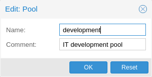
A resource pool is a set of virtual machines, containers, and storage devices. It is useful for permission handling in cases where certain users should have controlled access to a specific set of resources, as it allows for a single permission to be applied to a set of elements, rather than having to manage this on a per-resource basis. Resource pools are often used in tandem with groups, so that the members of a group have permissions on a set of machines and storage.
14.5. Authentication Realms
As Proxmox VE users are just counterparts for users existing on some external realm, the realms have to be configured in /etc/pve/domains.cfg. The following realms (authentication methods) are available:
- Linux PAM Standard Authentication
-
Linux PAM is a framework for system-wide user authentication. These users are created on the host system with commands such as adduser. If PAM users exist on the Proxmox VE host system, corresponding entries can be added to Proxmox VE, to allow these users to log in via their system username and password.
- Proxmox VE Authentication Server
-
This is a Unix-like password store, which stores hashed passwords in /etc/pve/priv/shadow.cfg. Passwords are hashed using the SHA-256 hashing algorithm. This is the most convenient realm for small-scale (or even mid-scale) installations, where users do not need access to anything outside of Proxmox VE. In this case, users are fully managed by Proxmox VE and are able to change their own passwords via the GUI.
- LDAP
-
LDAP (Lightweight Directory Access Protocol) is an open, cross-platform protocol for authentication using directory services. OpenLDAP is a popular open-source implementations of the LDAP protocol.
- Microsoft Active Directory (AD)
-
Microsoft Active Directory (AD) is a directory service for Windows domain networks and is supported as an authentication realm for Proxmox VE. It supports LDAP as an authentication protocol.
- OpenID Connect
-
OpenID Connect is implemented as an identity layer on top of the OATH 2.0 protocol. It allows clients to verify the identity of the user, based on authentication performed by an external authorization server.
14.5.1. Linux PAM Standard Authentication
As Linux PAM corresponds to host system users, a system user must exist on each node which the user is allowed to log in on. The user authenticates with their usual system password. This realm is added by default and can’t be removed. In terms of configurability, an administrator can choose to require two-factor authentication with logins from the realm and to set the realm as the default authentication realm.
14.5.2. Proxmox VE Authentication Server
The Proxmox VE authentication server realm is a simple Unix-like password store. The realm is created by default, and as with Linux PAM, the only configuration items available are the ability to require two-factor authentication for users of the realm, and to set it as the default realm for login.
Unlike the other Proxmox VE realm types, users are created and authenticated entirely through Proxmox VE, rather than authenticating against another system. Hence, you are required to set a password for this type of user upon creation.
14.5.3. LDAP
You can also use an external LDAP server for user authentication (for examle, OpenLDAP). In this realm type, users are searched under a Base Domain Name (base_dn), using the username attribute specified in the User Attribute Name (user_attr) field.
A server and optional fallback server can be configured, and the connection can be encrypted via SSL. Furthermore, filters can be configured for directories and groups. Filters allow you to further limit the scope of the realm.
For instance, if a user is represented via the following LDIF dataset:
# user1 of People at ldap-test.com
dn: uid=user1,ou=People,dc=ldap-test,dc=com
objectClass: top
objectClass: person
objectClass: organizationalPerson
objectClass: inetOrgPerson
uid: user1
cn: Test User 1
sn: Testers
description: This is the first test user.
The Base Domain Name would be ou=People,dc=ldap-test,dc=com and the user attribute would be uid.
If Proxmox VE needs to authenticate (bind) to the LDAP server before being able to query and authenticate users, a bind domain name can be configured via the bind_dn property in /etc/pve/domains.cfg. Its password then has to be stored in /etc/pve/priv/ldap/<realmname>.pw (for example, /etc/pve/priv/ldap/my-ldap.pw). This file should contain a single line with the raw password.
To verify certificates, you need to set capath. You can set it either directly to the CA certificate of your LDAP server, or to the system path containing all trusted CA certificates (/etc/ssl/certs). Additionally, you need to set the verify option, which can also be done over the web interface.
The main configuration options for an LDAP server realm are as follows:
-
Realm (realm): The realm identifier for Proxmox VE users
-
Base Domain Name (base_dn): The directory which users are searched under
-
User Attribute Name (user_attr): The LDAP attribute containing the username that users will log in with
-
Server (server1): The server hosting the LDAP directory
-
Fallback Server (server2): An optional fallback server address, in case the primary server is unreachable
-
Port (port): The port that the LDAP server listens on
|
|
In order to allow a particular user to authenticate using the LDAP server, you must also add them as a user of that realm from the Proxmox VE server. This can be carried out automatically with syncing. |
14.5.4. Microsoft Active Directory (AD)
To set up Microsoft AD as a realm, a server address and authentication domain need to be specified. Active Directory supports most of the same properties as LDAP, such as an optional fallback server, port, and SSL encryption. Furthermore, users can be added to Proxmox VE automatically via sync operations, after configuration.
As with LDAP, if Proxmox VE needs to authenticate before it binds to the AD server, you must configure the Bind User (bind_dn) property. This property is typically required by default for Microsoft AD.
The main configuration settings for Microsoft Active Directory are:
-
Realm (realm): The realm identifier for Proxmox VE users
-
Domain (domain): The AD domain of the server
-
Server (server1): The FQDN or IP address of the server
-
Fallback Server (server2): An optional fallback server address, in case the primary server is unreachable
-
Port (port): The port that the Microsoft AD server listens on
|
|
Microsoft AD normally checks values like usernames without case sensitivity. To make Proxmox VE do the same, you can disable the default case-sensitive option by editing the realm in the web UI, or using the CLI (change the ID with the realm ID): pveum realm modify ID --case-sensitive 0 |
14.5.5. Syncing LDAP-Based Realms
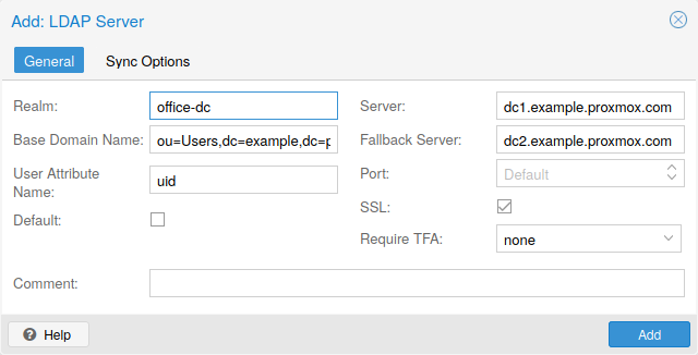
It’s possible to automatically sync users and groups for LDAP-based realms (LDAP & Microsoft Active Directory), rather than having to add them to Proxmox VE manually. You can access the sync options from the Add/Edit window of the web interface’s Authentication panel or via the pveum realm add/modify commands. You can then carry out the sync operation from the Authentication panel of the GUI or using the following command:
pveum realm sync <realm>
Users and groups are synced to the cluster-wide configuration file, /etc/pve/user.cfg.
Attributes to Properties
If the sync response includes user attributes, they will be synced into the matching user property in the user.cfg. For example: firstname or lastname.
If the names of the attributes are not matching the Proxmox VE properties, you can set a custom field-to-field map in the config by using the sync_attributes option.
How such properties are handled if anything vanishes can be controlled via the sync options, see below.
Sync Configuration
The configuration options for syncing LDAP-based realms can be found in the Sync Options tab of the Add/Edit window.
The configuration options are as follows:
-
Bind User (bind_dn): Refers to the LDAP account used to query users and groups. This account needs access to all desired entries. If it’s set, the search will be carried out via binding; otherwise, the search will be carried out anonymously. The user must be a complete LDAP formatted distinguished name (DN), for example, cn=admin,dc=example,dc=com.
-
Groupname attr. (group_name_attr): Represents the users' groups. Only entries which adhere to the usual character limitations of the user.cfg are synced. Groups are synced with -$realm attached to the name, in order to avoid naming conflicts. Please ensure that a sync does not overwrite manually created groups.
-
User classes (user_classes): Objects classes associated with users.
-
Group classes (group_classes): Objects classes associated with groups.
-
E-Mail attribute: If the LDAP-based server specifies user email addresses, these can also be included in the sync by setting the associated attribute here. From the command line, this is achievable through the --sync_attributes parameter.
-
User Filter (filter): For further filter options to target specific users.
-
Group Filter (group_filter): For further filter options to target specific groups.
|
|
Filters allow you to create a set of additional match criteria, to narrow down the scope of a sync. Information on available LDAP filter types and their usage can be found at ldap.com. |
Sync Options
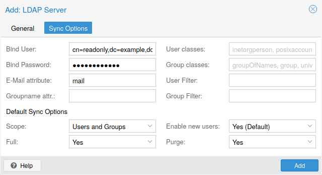
In addition to the options specified in the previous section, you can also configure further options that describe the behavior of the sync operation.
These options are either set as parameters before the sync, or as defaults via the realm option sync-defaults-options.
The main options for syncing are:
-
Scope (scope): The scope of what to sync. It can be either users, groups or both.
-
Enable new (enable-new): If set, the newly synced users are enabled and can log in. The default is true.
-
Remove Vanished (remove-vanished): This is a list of options which, when activated, determine if they are removed when they are not returned from the sync response. The options are:
-
ACL (acl): Remove ACLs of users and groups which were not returned returned in the sync response. This most often makes sense together with Entry.
-
Entry (entry): Removes entries (i.e. users and groups) when they are not returned in the sync response.
-
Properties (properties): Removes properties of entries where the user in the sync response did not contain those attributes. This includes all properties, even those never set by a sync. Exceptions are tokens and the enable flag, these will be retained even with this option enabled.
-
-
Preview (dry-run): No data is written to the config. This is useful if you want to see which users and groups would get synced to the user.cfg.
Reserved characters
Certain characters are reserved (see RFC2253) and cannot be easily used in attribute values in DNs without being escaped properly.
Following characters need escaping:
-
Space ( ) at the beginning or end
-
Number sign (#) at the beginning
-
Comma (,)
-
Plus sign (+)
-
Double quote (")
-
Forward slashes (/)
-
Angle brackets (<>)
-
Semicolon (;)
-
Equals sign (=)
To use such characters in DNs, surround the attribute value in double quotes. For example, to bind with a user with the CN (Common Name) Example, User, use CN="Example, User",OU=people,DC=example,DC=com as value for bind_dn.
This applies to the base_dn, bind_dn, and group_dn attributes.
|
|
Users with colons and forward slashes cannot be synced since these are reserved characters in usernames. |
14.5.6. OpenID Connect
The main OpenID Connect configuration options are:
-
Issuer URL (issuer-url): This is the URL of the authorization server. Proxmox uses the OpenID Connect Discovery protocol to automatically configure further details.
While it is possible to use unencrypted http:// URLs, we strongly recommend to use encrypted https:// connections.
-
Realm (realm): The realm identifier for Proxmox VE users
-
Client ID (client-id): OpenID Client ID.
-
Client Key (client-key): Optional OpenID Client Key.
-
Autocreate Users (autocreate): Automatically create users if they do not exist. While authentication is done at the OpenID server, all users still need an entry in the Proxmox VE user configuration. You can either add them manually, or use the autocreate option to automatically add new users.
-
Username Claim (username-claim): OpenID claim used to generate the unique username (subject, username or email).
Username mapping
The OpenID Connect specification defines a single unique attribute (claim in OpenID terms) named subject. By default, we use the value of this attribute to generate Proxmox VE usernames, by simple adding @ and the realm name: ${subject}@${realm}.
Unfortunately, most OpenID servers use random strings for subject, like DGH76OKH34BNG3245SB, so a typical username would look like DGH76OKH34BNG3245SB@yourrealm. While unique, it is difficult for humans to remember such random strings, making it quite impossible to associate real users with this.
The username-claim setting allows you to use other attributes for the username mapping. Setting it to username is preferred if the OpenID Connect server provides that attribute and guarantees its uniqueness.
Another option is to use email, which also yields human readable usernames. Again, only use this setting if the server guarantees the uniqueness of this attribute.
Examples
Here is an example of creating an OpenID realm using Google. You need to replace --client-id and --client-key with the values from your Google OpenID settings.
pveum realm add myrealm1 --type openid --issuer-url https://accounts.google.com --client-id XXXX --client-key YYYY --username-claim email
The above command uses --username-claim email, so that the usernames on the Proxmox VE side look like example.user@google.com@myrealm1.
Keycloak (https://www.keycloak.org/) is a popular open source Identity and Access Management tool, which supports OpenID Connect. In the following example, you need to replace the --issuer-url and --client-id with your information:
pveum realm add myrealm2 --type openid --issuer-url https://your.server:8080/realms/your-realm --client-id XXX --username-claim username
Using --username-claim username enables simple usernames on the Proxmox VE side, like example.user@myrealm2.
|
|
You need to ensure that the user is not allowed to edit the username setting themselves (on the Keycloak server). |
14.6. Two-Factor Authentication
There are two ways to use two-factor authentication:
It can be required by the authentication realm, either via TOTP (Time-based One-Time Password) or YubiKey OTP. In this case, a newly created user needs to have their keys added immediately, as there is no way to log in without the second factor. In the case of TOTP, users can also change the TOTP later on, provided they can log in first.
Alternatively, users can choose to opt-in to two-factor authentication later on, even if the realm does not enforce it.
14.6.1. Available Second Factors
You can set up multiple second factors, in order to avoid a situation in which losing your smartphone or security key locks you out of your account permanently.
The following two-factor authentication methods are available in addition to realm-enforced TOTP and YubiKey OTP:
-
User configured TOTP (Time-based One-Time Password). A short code derived from a shared secret and the current time, it changes every 30 seconds.
-
WebAuthn (Web Authentication). A general standard for authentication. It is implemented by various security devices, like hardware keys or trusted platform modules (TPM) from a computer or smart phone.
-
Single use Recovery Keys. A list of keys which should either be printed out and locked in a secure place or saved digitally in an electronic vault. Each key can be used only once. These are perfect for ensuring that you are not locked out, even if all of your other second factors are lost or corrupt.
Before WebAuthn was supported, U2F could be setup by the user. Existing U2F factors can still be used, but it is recommended to switch to WebAuthn, once it is configured on the server.
14.6.2. Realm Enforced Two-Factor Authentication
This can be done by selecting one of the available methods via the TFA dropdown box when adding or editing an Authentication Realm. When a realm has TFA enabled, it becomes a requirement, and only users with configured TFA will be able to log in.
Currently there are two methods available:
- Time-based OATH (TOTP)
-
This uses the standard HMAC-SHA1 algorithm, where the current time is hashed with the user’s configured key. The time step and password length parameters are configurable.
A user can have multiple keys configured (separated by spaces), and the keys can be specified in Base32 (RFC3548) or hexadecimal notation.
Proxmox VE provides a key generation tool (oathkeygen) which prints out a random key in Base32 notation, that can be used directly with various OTP tools, such as the oathtool command-line tool, or on Android Google Authenticator, FreeOTP, andOTP or similar applications.
- YubiKey OTP
-
For authenticating via a YubiKey a Yubico API ID, API KEY and validation server URL must be configured, and users must have a YubiKey available. In order to get the key ID from a YubiKey, you can trigger the YubiKey once after connecting it via USB, and copy the first 12 characters of the typed password into the user’s Key IDs field.
Please refer to the YubiKey OTP documentation for how to use the YubiCloud or host your own verification server.
14.6.3. Limits and Lockout of Two-Factor Authentication
A second factor is meant to protect users if their password is somehow leaked or guessed. However, some factors could still be broken by brute force. For this reason, users will be locked out after too many failed 2nd factor login attempts.
For TOTP, 8 failed attempts will disable the user’s TOTP factors. They are unlocked when logging in with a recovery key. If TOTP was the only available factor, admin intervention is required, and it is highly recommended to require the user to change their password immediately.
Since FIDO2/Webauthn and recovery keys are less susceptible to brute force attacks, the limit there is higher (100 tries), but all second factors are blocked for an hour when exceeded.
An admin can unlock a user’s Two-Factor Authentication at any time via the user list in the UI or the command line:
pveum user tfa unlock joe@pve
14.6.4. User Configured TOTP Authentication
Users can choose to enable TOTP or WebAuthn as a second factor on login, via the TFA button in the user list (unless the realm enforces YubiKey OTP).
Users can always add and use one time Recovery Keys.
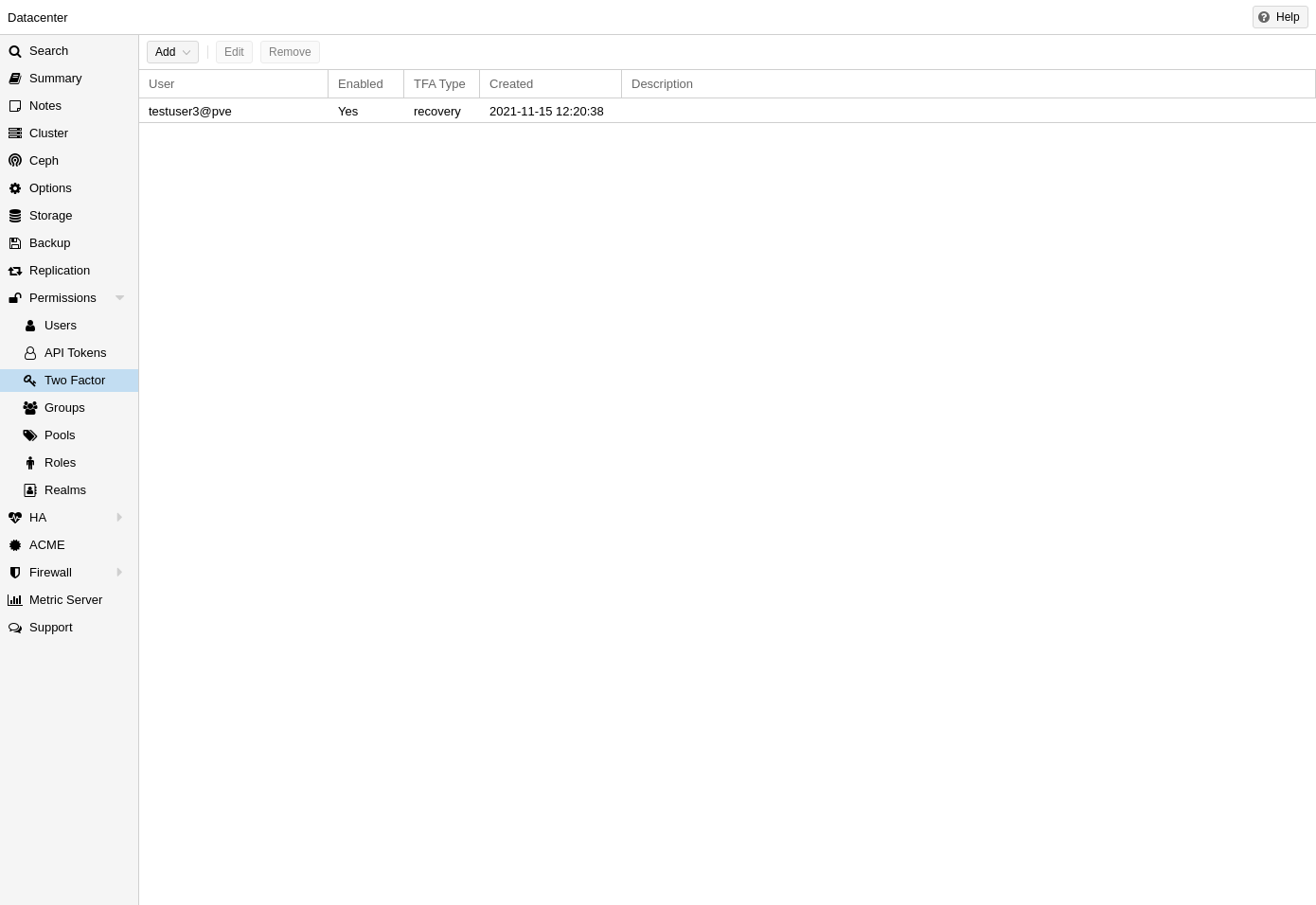
After opening the TFA window, the user is presented with a dialog to set up TOTP authentication. The Secret field contains the key, which can be randomly generated via the Randomize button. An optional Issuer Name can be added to provide information to the TOTP app about what the key belongs to. Most TOTP apps will show the issuer name together with the corresponding OTP values. The username is also included in the QR code for the TOTP app.
After generating a key, a QR code will be displayed, which can be used with most OTP apps such as FreeOTP. The user then needs to verify the current user password (unless logged in as root), as well as the ability to correctly use the TOTP key, by typing the current OTP value into the Verification Code field and pressing the Apply button.
14.6.5. TOTP
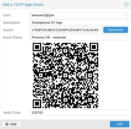
There is no server setup required. Simply install a TOTP app on your smartphone (for example, FreeOTP) and use the Proxmox Backup Server web interface to add a TOTP factor.
14.6.6. WebAuthn
For WebAuthn to work, you need to have two things:
-
A trusted HTTPS certificate (for example, by using Let’s Encrypt). While it probably works with an untrusted certificate, some browsers may warn or refuse WebAuthn operations if it is not trusted.
-
Setup the WebAuthn configuration (see Datacenter → Options → WebAuthn Settings in the Proxmox VE web interface). This can be auto-filled in most setups.
Once you have fulfilled both of these requirements, you can add a WebAuthn configuration in the Two Factor panel under Datacenter → Permissions → Two Factor.
14.6.7. Recovery Keys
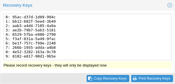
Recovery key codes do not need any preparation; you can simply create a set of recovery keys in the Two Factor panel under Datacenter → Permissions → Two Factor.
|
|
There can only be one set of single-use recovery keys per user at any time. |
14.6.8. Server Side Webauthn Configuration
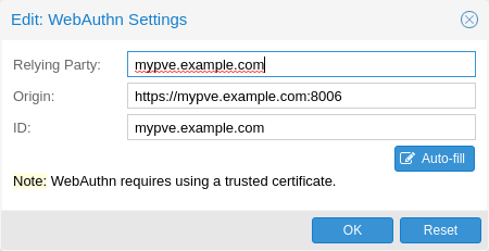
To allow users to use WebAuthn authentication, it is necessaary to use a valid domain with a valid SSL certificate, otherwise some browsers may warn or refuse to authenticate altogether.
|
|
Changing the WebAuthn configuration may render all existing WebAuthn registrations unusable! |
This is done via /etc/pve/datacenter.cfg. For instance:
webauthn: rp=mypve.example.com,origin=https://mypve.example.com:8006,id=mypve.example.com
14.6.9. Server Side U2F Configuration
|
|
It is recommended to use WebAuthn instead. |
To allow users to use U2F authentication, it may be necessary to use a valid
domain with a valid SSL certificate, otherwise, some browsers may print
a warning or reject U2F usage altogether. Initially, an AppId
[AppId https://developers.yubico.com/U2F/App_ID.html]
needs to be configured.
|
|
Changing the AppId will render all existing U2F registrations unusable! |
This is done via /etc/pve/datacenter.cfg. For instance:
u2f: appid=https://mypve.example.com:8006
For a single node, the AppId can simply be the address of the web interface, exactly as it is used in the browser, including the https:// and the port, as shown above. Please note that some browsers may be more strict than others when matching AppIds.
When using multiple nodes, it is best to have a separate https server
providing an appid.json
[Multi-facet apps: https://developers.yubico.com/U2F/App_ID.html]
file, as it seems to be compatible with most
browsers. If all nodes use subdomains of the same top level domain, it may be
enough to use the TLD as AppId. It should however be noted that some browsers
may not accept this.
|
|
A bad AppId will usually produce an error, but we have encountered situations when this does not happen, particularly when using a top level domain AppId for a node that is accessed via a subdomain in Chromium. For this reason it is recommended to test the configuration with multiple browsers, as changing the AppId later will render existing U2F registrations unusable. |
14.6.10. Activating U2F as a User
To enable U2F authentication, open the TFA window’s U2F tab, type in the current password (unless logged in as root), and press the Register button. If the server is set up correctly and the browser accepts the server’s provided AppId, a message will appear prompting the user to press the button on the U2F device (if it is a YubiKey, the button light should be toggling on and off steadily, roughly twice per second).
Firefox users may need to enable security.webauth.u2f via about:config before they can use a U2F token.
14.7. Permission Management
In order for a user to perform an action (such as listing, modifying or deleting parts of a VM’s configuration), the user needs to have the appropriate permissions.
Proxmox VE uses a role and path based permission management system. An entry in the permissions table allows a user, group or token to take on a specific role when accessing an object or path. This means that such an access rule can be represented as a triple of (path, user, role), (path, group, role) or (path, token, role), with the role containing a set of allowed actions, and the path representing the target of these actions.
14.7.1. Roles
A role is simply a list of privileges. Proxmox VE comes with a number of predefined roles, which satisfy most requirements.
-
Administrator: has full privileges
-
NoAccess: has no privileges (used to forbid access)
-
PVEAdmin: can do most tasks, but has no rights to modify system settings (Sys.PowerMgmt, Sys.Modify, Realm.Allocate) or permissions (Permissions.Modify)
-
PVEAuditor: has read only access
-
PVEDatastoreAdmin: create and allocate backup space and templates
-
PVEDatastoreUser: allocate backup space and view storage
-
PVEMappingAdmin: manage resource mappings
-
PVEMappingUser: view and use resource mappings
-
PVEPoolAdmin: allocate pools
-
PVEPoolUser: view pools
-
PVESDNAdmin: manage SDN configuration
-
PVESDNUser: access to bridges/vnets
-
PVESysAdmin: audit, system console and system logs
-
PVETemplateUser: view and clone templates
-
PVEUserAdmin: manage users
-
PVEVMAdmin: fully administer VMs
-
PVEVMUser: view, backup, configure CD-ROM, VM console, VM power management
You can see the whole set of predefined roles in the GUI.
You can add new roles via the GUI or the command line.
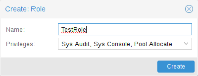
From the GUI, navigate to the Permissions → Roles tab from Datacenter and click on the Create button. There you can set a role name and select any desired privileges from the Privileges drop-down menu.
To add a role through the command line, you can use the pveum CLI tool, for example:
pveum role add VM_Power-only --privs "VM.PowerMgmt VM.Console"
pveum role add Sys_Power-only --privs "Sys.PowerMgmt Sys.Console"
|
|
Roles starting with PVE are always builtin, custom roles are not allowed use this reserved prefix. |
14.7.2. Privileges
A privilege is the right to perform a specific action. To simplify management, lists of privileges are grouped into roles, which can then be used in the permission table. Note that privileges cannot be directly assigned to users and paths without being part of a role.
We currently support the following privileges:
- Node / System related privileges
-
-
Group.Allocate: create/modify/remove groups
-
Mapping.Audit: view resource mappings
-
Mapping.Modify: manage resource mappings
-
Mapping.Use: use resource mappings
-
Permissions.Modify: modify access permissions
-
Pool.Allocate: create/modify/remove a pool
-
Pool.Audit: view a pool
-
Realm.AllocateUser: assign user to a realm
-
Realm.Allocate: create/modify/remove authentication realms
-
SDN.Allocate: manage SDN configuration
-
SDN.Audit: view SDN configuration
-
Sys.Audit: view node status/config, Corosync cluster config, and HA config
-
Sys.Console: console access to node
-
Sys.Incoming: allow incoming data streams from other clusters (experimental)
-
Sys.Modify: create/modify/remove node network parameters
-
Sys.PowerMgmt: node power management (start, stop, reset, shutdown, …)
-
Sys.Syslog: view syslog
-
User.Modify: create/modify/remove user access and details.
-
- Virtual machine related privileges
-
-
SDN.Use: access SDN vnets and local network bridges
-
VM.Allocate: create/remove VM on a server
-
VM.Audit: view VM config
-
VM.Backup: backup/restore VMs
-
VM.Clone: clone/copy a VM
-
VM.Config.CDROM: eject/change CD-ROM
-
VM.Config.CPU: modify CPU settings
-
VM.Config.Cloudinit: modify Cloud-init parameters
-
VM.Config.Disk: add/modify/remove disks
-
VM.Config.HWType: modify emulated hardware types
-
VM.Config.Memory: modify memory settings
-
VM.Config.Network: add/modify/remove network devices
-
VM.Config.Options: modify any other VM configuration
-
VM.Console: console access to VM
-
VM.Migrate: migrate VM to alternate server on cluster
-
VM.Monitor: access to VM monitor (kvm)
-
VM.PowerMgmt: power management (start, stop, reset, shutdown, …)
-
VM.Snapshot.Rollback: rollback VM to one of its snapshots
-
VM.Snapshot: create/delete VM snapshots
-
- Storage related privileges
-
-
Datastore.Allocate: create/modify/remove a datastore and delete volumes
-
Datastore.AllocateSpace: allocate space on a datastore
-
Datastore.AllocateTemplate: allocate/upload templates and ISO images
-
Datastore.Audit: view/browse a datastore
-
|
|
Both Permissions.Modify and Sys.Modify should be handled with care, as they allow modifying aspects of the system and its configuration that are dangerous or sensitive. |
|
|
Carefully read the section about inheritance below to understand how assigned roles (and their privileges) are propagated along the ACL tree. |
14.7.3. Objects and Paths
Access permissions are assigned to objects, such as virtual machines, storages or resource pools. We use file system like paths to address these objects. These paths form a natural tree, and permissions of higher levels (shorter paths) can optionally be propagated down within this hierarchy.
Paths can be templated. When an API call requires permissions on a templated path, the path may contain references to parameters of the API call. These references are specified in curly braces. Some parameters are implicitly taken from the API call’s URI. For instance, the permission path /nodes/{node} when calling /nodes/mynode/status requires permissions on /nodes/mynode, while the path {path} in a PUT request to /access/acl refers to the method’s path parameter.
Some examples are:
-
/nodes/{node}: Access to Proxmox VE server machines
-
/vms: Covers all VMs
-
/vms/{vmid}: Access to specific VMs
-
/storage/{storeid}: Access to a specific storage
-
/pool/{poolname}: Access to resources contained in a specific pool
-
/access/groups: Group administration
-
/access/realms/{realmid}: Administrative access to realms
Inheritance
As mentioned earlier, object paths form a file system like tree, and permissions can be inherited by objects down that tree (the propagate flag is set by default). We use the following inheritance rules:
-
Permissions for individual users always replace group permissions.
-
Permissions for groups apply when the user is member of that group.
-
Permissions on deeper levels replace those inherited from an upper level.
-
NoAccess cancels all other roles on a given path.
Additionally, privilege separated tokens can never have permissions on any given path that their associated user does not have.
14.7.4. Pools
Pools can be used to group a set of virtual machines and datastores. You can then simply set permissions on pools (/pool/{poolid}), which are inherited by all pool members. This is a great way to simplify access control.
14.7.5. Which Permissions Do I Need?
The required API permissions are documented for each individual method, and can be found at https://pve.proxmox.com/pve-docs/api-viewer/.
The permissions are specified as a list, which can be interpreted as a tree of logic and access-check functions:
- ["and", <subtests>...] and ["or", <subtests>...]
-
Each(and) or any(or) further element in the current list has to be true.
- ["perm", <path>, [ <privileges>... ], <options>...]
-
The path is a templated parameter (see Objects and Paths). All (or, if the any option is used, any) of the listed privileges must be allowed on the specified path. If a require-param option is specified, then its specified parameter is required even if the API call’s schema otherwise lists it as being optional.
- ["userid-group", [ <privileges>... ], <options>...]
-
The caller must have any of the listed privileges on /access/groups. In addition, there are two possible checks, depending on whether the groups_param option is set:
-
groups_param is set: The API call has a non-optional groups parameter and the caller must have any of the listed privileges on all of the listed groups.
-
groups_param is not set: The user passed via the userid parameter must exist and be part of a group on which the caller has any of the listed privileges (via the /access/groups/<group> path).
-
- ["userid-param", "self"]
-
The value provided for the API call’s userid parameter must refer to the user performing the action (usually in conjunction with or, to allow users to perform an action on themselves, even if they don’t have elevated privileges).
- ["userid-param", "Realm.AllocateUser"]
-
The user needs Realm.AllocateUser access to /access/realm/<realm>, with <realm> referring to the realm of the user passed via the userid parameter. Note that the user does not need to exist in order to be associated with a realm, since user IDs are passed in the form of <username>@<realm>.
- ["perm-modify", <path>]
-
The path is a templated parameter (see Objects and Paths). The user needs either the Permissions.Modify privilege or, depending on the path, the following privileges as a possible substitute:
-
/storage/...: requires 'Datastore.Allocate`
-
/vms/...: requires 'VM.Allocate`
-
/pool/...: requires 'Pool.Allocate`
If the path is empty, Permissions.Modify on /access is required.
If the user does not have the Permissions.Modify privilege, they can only delegate subsets of their own privileges on the given path (e.g., a user with PVEVMAdmin could assign PVEVMUser, but not PVEAdmin).
-
14.8. Command-line Tool
Most users will simply use the GUI to manage users. But there is also a fully featured command-line tool called pveum (short for “Proxmox VE User Manager”). Please note that all Proxmox VE command-line tools are wrappers around the API, so you can also access those functions through the REST API.
Here are some simple usage examples. To show help, type:
pveum
or (to show detailed help about a specific command)
pveum help user addCreate a new user:
pveum user add testuser@pve -comment "Just a test"Set or change the password (not all realms support this):
pveum passwd testuser@pve
Disable a user:
pveum user modify testuser@pve -enable 0Create a new group:
pveum group add testgroup
Create a new role:
pveum role add PVE_Power-only -privs "VM.PowerMgmt VM.Console"14.9. Real World Examples
14.9.1. Administrator Group
It is possible that an administrator would want to create a group of users with full administrator rights (without using the root account).
To do this, first define the group:
pveum group add admin -comment "System Administrators"Then assign the role:
pveum acl modify / -group admin -role AdministratorFinally, you can add users to the new admin group:
pveum user modify testuser@pve -group admin
14.9.2. Auditors
You can give read only access to users by assigning the PVEAuditor role to users or groups.
Example 1: Allow user joe@pve to see everything
pveum acl modify / -user joe@pve -role PVEAuditorExample 2: Allow user joe@pve to see all virtual machines
pveum acl modify /vms -user joe@pve -role PVEAuditor
14.9.3. Delegate User Management
If you want to delegate user management to user joe@pve, you can do that with:
pveum acl modify /access -user joe@pve -role PVEUserAdmin
User joe@pve can now add and remove users, and change other user attributes, such as passwords. This is a very powerful role, and you most likely want to limit it to selected realms and groups. The following example allows joe@pve to modify users within the realm pve, if they are members of group customers:
 pveum acl modify /access/realm/pve -user joe@pve -role PVEUserAdmin
 pveum acl modify /access/groups/customers -user joe@pve -role PVEUserAdmin
|
|
The user is able to add other users, but only if they are members of the group customers and within the realm pve. |
14.9.4. Limited API Token for Monitoring
Permissions on API tokens are always a subset of those of their corresponding user, meaning that an API token can’t be used to carry out a task that the backing user has no permission to do. This section will demonstrate how you can use an API token with separate privileges, to limit the token owner’s permissions further.
Give the user joe@pve the role PVEVMAdmin on all VMs:
pveum acl modify /vms -user joe@pve -role PVEVMAdmin
Add a new API token with separate privileges, which is only allowed to view VM information (for example, for monitoring purposes):
 pveum user token add joe@pve monitoring -privsep 1
 pveum acl modify /vms -token 'joe@pve!monitoring' -role PVEAuditor
Verify the permissions of the user and token:
 pveum user permissions joe@pve
 pveum user token permissions joe@pve monitoring
14.9.5. Resource Pools
An enterprise is usually structured into several smaller departments, and it is common that you want to assign resources and delegate management tasks to each of these. Let’s assume that you want to set up a pool for a software development department. First, create a group:
pveum group add developers -comment "Our software developers"Now we create a new user which is a member of that group:
pveum user add developer1@pve -group developers -password
|
|
The "-password" parameter will prompt you for a password |
Then we create a resource pool for our development department to use:
pveum pool add dev-pool --comment "IT development pool"Finally, we can assign permissions to that pool:
pveum acl modify /pool/dev-pool/ -group developers -role PVEAdminOur software developers can now administer the resources assigned to that pool.
15. High Availability
Our modern society depends heavily on information provided by computers over the network. Mobile devices amplified that dependency, because people can access the network any time from anywhere. If you provide such services, it is very important that they are available most of the time.
We can mathematically define the availability as the ratio of (A), the total time a service is capable of being used during a given interval to (B), the length of the interval. It is normally expressed as a percentage of uptime in a given year.
| Availability % | Downtime per year |
|---|---|
99 |
3.65 days |
99.9 |
8.76 hours |
99.99 |
52.56 minutes |
99.999 |
5.26 minutes |
99.9999 |
31.5 seconds |
99.99999 |
3.15 seconds |
There are several ways to increase availability. The most elegant solution is to rewrite your software, so that you can run it on several hosts at the same time. The software itself needs to have a way to detect errors and do failover. If you only want to serve read-only web pages, then this is relatively simple. However, this is generally complex and sometimes impossible, because you cannot modify the software yourself. The following solutions works without modifying the software:
-
Use reliable “server” components
Computer components with the same functionality can have varying reliability numbers, depending on the component quality. Most vendors sell components with higher reliability as “server” components - usually at higher price. -
Eliminate single point of failure (redundant components)
-
use an uninterruptible power supply (UPS)
-
use redundant power supplies in your servers
-
use ECC-RAM
-
use redundant network hardware
-
use RAID for local storage
-
use distributed, redundant storage for VM data
-
-
Reduce downtime
-
rapidly accessible administrators (24/7)
-
availability of spare parts (other nodes in a Proxmox VE cluster)
-
automatic error detection (provided by ha-manager)
-
automatic failover (provided by ha-manager)
-
Virtualization environments like Proxmox VE make it much easier to reach high availability because they remove the “hardware” dependency. They also support the setup and use of redundant storage and network devices, so if one host fails, you can simply start those services on another host within your cluster.
Better still, Proxmox VE provides a software stack called ha-manager, which can do that automatically for you. It is able to automatically detect errors and do automatic failover.
Proxmox VE ha-manager works like an “automated” administrator. First, you configure what resources (VMs, containers, …) it should manage. Then, ha-manager observes the correct functionality, and handles service failover to another node in case of errors. ha-manager can also handle normal user requests which may start, stop, relocate and migrate a service.
But high availability comes at a price. High quality components are more expensive, and making them redundant doubles the costs at least. Additional spare parts increase costs further. So you should carefully calculate the benefits, and compare with those additional costs.
|
|
Increasing availability from 99% to 99.9% is relatively simple. But increasing availability from 99.9999% to 99.99999% is very hard and costly. ha-manager has typical error detection and failover times of about 2 minutes, so you can get no more than 99.999% availability. |
15.1. Requirements
You must meet the following requirements before you start with HA:
-
at least three cluster nodes (to get reliable quorum)
-
shared storage for VMs and containers
-
hardware redundancy (everywhere)
-
use reliable “server” components
-
hardware watchdog - if not available we fall back to the linux kernel software watchdog (softdog)
-
optional hardware fencing devices
15.2. Resources
We call the primary management unit handled by ha-manager a resource. A resource (also called “service”) is uniquely identified by a service ID (SID), which consists of the resource type and a type specific ID, for example vm:100. That example would be a resource of type vm (virtual machine) with the ID 100.
For now we have two important resources types - virtual machines and containers. One basic idea here is that we can bundle related software into such a VM or container, so there is no need to compose one big service from other services, as was done with rgmanager. In general, a HA managed resource should not depend on other resources.
15.3. Management Tasks
This section provides a short overview of common management tasks. The first step is to enable HA for a resource. This is done by adding the resource to the HA resource configuration. You can do this using the GUI, or simply use the command-line tool, for example:
# ha-manager add vm:100
The HA stack now tries to start the resources and keep them running. Please note that you can configure the “requested” resources state. For example you may want the HA stack to stop the resource:
# ha-manager set vm:100 --state stopped
and start it again later:
# ha-manager set vm:100 --state started
You can also use the normal VM and container management commands. They automatically forward the commands to the HA stack, so
# qm start 100
simply sets the requested state to started. The same applies to qm stop, which sets the requested state to stopped.
|
|
The HA stack works fully asynchronous and needs to communicate with other cluster members. Therefore, it takes some seconds until you see the result of such actions. |
To view the current HA resource configuration use:
# ha-manager config
vm:100
        state stopped
And you can view the actual HA manager and resource state with:
# ha-manager status
quorum OK
master node1 (active, Wed Nov 23 11:07:23 2016)
lrm elsa (active, Wed Nov 23 11:07:19 2016)
service vm:100 (node1, started)
You can also initiate resource migration to other nodes:
# ha-manager migrate vm:100 node2
This uses online migration and tries to keep the VM running. Online migration needs to transfer all used memory over the network, so it is sometimes faster to stop the VM, then restart it on the new node. This can be done using the relocate command:
# ha-manager relocate vm:100 node2
Finally, you can remove the resource from the HA configuration using the following command:
# ha-manager remove vm:100
|
|
This does not start or stop the resource. |
But all HA related tasks can be done in the GUI, so there is no need to use the command line at all.
15.4. How It Works
This section provides a detailed description of the Proxmox VE HA manager internals. It describes all involved daemons and how they work together. To provide HA, two daemons run on each node:
- pve-ha-lrm
-
The local resource manager (LRM), which controls the services running on the local node. It reads the requested states for its services from the current manager status file and executes the respective commands.
- pve-ha-crm
-
The cluster resource manager (CRM), which makes the cluster-wide decisions. It sends commands to the LRM, processes the results, and moves resources to other nodes if something fails. The CRM also handles node fencing.
|
|
Locks in the LRM & CRM Locks are provided by our distributed configuration file system (pmxcfs).
They are used to guarantee that each LRM is active once and working. As an
LRM only executes actions when it holds its lock, we can mark a failed node
as fenced if we can acquire its lock. This then lets us recover any failed
HA services securely without any interference from the now unknown failed node.
This all gets supervised by the CRM which currently holds the manager master
lock. |
15.4.1. Service States
The CRM uses a service state enumeration to record the current service state. This state is displayed on the GUI and can be queried using the ha-manager command-line tool:
# ha-manager status
quorum OK
master elsa (active, Mon Nov 21 07:23:29 2016)
lrm elsa (active, Mon Nov 21 07:23:22 2016)
service ct:100 (elsa, stopped)
service ct:102 (elsa, started)
service vm:501 (elsa, started)
Here is the list of possible states:
- stopped
-
Service is stopped (confirmed by LRM). If the LRM detects a stopped service is still running, it will stop it again.
- request_stop
-
Service should be stopped. The CRM waits for confirmation from the LRM.
- stopping
-
Pending stop request. But the CRM did not get the request so far.
- started
-
Service is active an LRM should start it ASAP if not already running. If the Service fails and is detected to be not running the LRM restarts it (see Start Failure Policy).
- starting
-
Pending start request. But the CRM has not got any confirmation from the LRM that the service is running.
- fence
-
Wait for node fencing as the service node is not inside the quorate cluster partition (see Fencing). As soon as node gets fenced successfully the service will be placed into the recovery state.
- recovery
-
Wait for recovery of the service. The HA manager tries to find a new node where the service can run on. This search depends not only on the list of online and quorate nodes, but also if the service is a group member and how such a group is limited. As soon as a new available node is found, the service will be moved there and initially placed into stopped state. If it’s configured to run the new node will do so.
- freeze
-
Do not touch the service state. We use this state while we reboot a node, or when we restart the LRM daemon (see Package Updates).
- ignored
-
Act as if the service were not managed by HA at all. Useful, when full control over the service is desired temporarily, without removing it from the HA configuration.
- migrate
-
Migrate service (live) to other node.
- error
-
Service is disabled because of LRM errors. Needs manual intervention (see Error Recovery).
- queued
-
Service is newly added, and the CRM has not seen it so far.
- disabled
-
Service is stopped and marked as disabled
15.4.2. Local Resource Manager
The local resource manager (pve-ha-lrm) is started as a daemon on boot and waits until the HA cluster is quorate and thus cluster-wide locks are working.
It can be in three states:
- wait for agent lock
-
The LRM waits for our exclusive lock. This is also used as idle state if no service is configured.
- active
-
The LRM holds its exclusive lock and has services configured.
- lost agent lock
-
The LRM lost its lock, this means a failure happened and quorum was lost.
After the LRM gets in the active state it reads the manager status file in /etc/pve/ha/manager_status and determines the commands it has to execute for the services it owns. For each command a worker gets started, these workers are running in parallel and are limited to at most 4 by default. This default setting may be changed through the datacenter configuration key max_worker. When finished the worker process gets collected and its result saved for the CRM.
|
|
Maximum Concurrent Worker Adjustment Tips The default value of at most 4 concurrent workers may be unsuited for
a specific setup. For example, 4 live migrations may occur at the same
time, which can lead to network congestions with slower networks and/or
big (memory wise) services. Also, ensure that in the worst case, congestion is
at a minimum, even if this means lowering the max_worker value. On the
contrary, if you have a particularly powerful, high-end setup you may also want
to increase it. |
Each command requested by the CRM is uniquely identifiable by a UID. When the worker finishes, its result will be processed and written in the LRM status file /etc/pve/nodes/<nodename>/lrm_status. There the CRM may collect it and let its state machine - respective to the commands output - act on it.
The actions on each service between CRM and LRM are normally always synced. This means that the CRM requests a state uniquely marked by a UID, the LRM then executes this action one time and writes back the result, which is also identifiable by the same UID. This is needed so that the LRM does not execute an outdated command. The only exceptions to this behaviour are the stop and error commands; these two do not depend on the result produced and are executed always in the case of the stopped state and once in the case of the error state.
|
|
Read the Logs The HA Stack logs every action it makes. This helps to understand what
and also why something happens in the cluster. Here its important to see
what both daemons, the LRM and the CRM, did. You may use
journalctl -u pve-ha-lrm on the node(s) where the service is and
the same command for the pve-ha-crm on the node which is the current master. |
15.4.3. Cluster Resource Manager
The cluster resource manager (pve-ha-crm) starts on each node and waits there for the manager lock, which can only be held by one node at a time. The node which successfully acquires the manager lock gets promoted to the CRM master.
It can be in three states:
- wait for agent lock
-
The CRM waits for our exclusive lock. This is also used as idle state if no service is configured
- active
-
The CRM holds its exclusive lock and has services configured
- lost agent lock
-
The CRM lost its lock, this means a failure happened and quorum was lost.
Its main task is to manage the services which are configured to be highly available and try to always enforce the requested state. For example, a service with the requested state started will be started if its not already running. If it crashes it will be automatically started again. Thus the CRM dictates the actions the LRM needs to execute.
When a node leaves the cluster quorum, its state changes to unknown. If the current CRM can then secure the failed node’s lock, the services will be stolen and restarted on another node.
When a cluster member determines that it is no longer in the cluster quorum, the LRM waits for a new quorum to form. As long as there is no quorum the node cannot reset the watchdog. This will trigger a reboot after the watchdog times out (this happens after 60 seconds).
15.5. HA Simulator
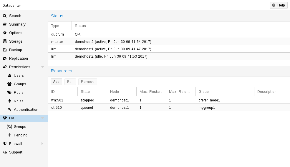
By using the HA simulator you can test and learn all functionalities of the Proxmox VE HA solutions.
By default, the simulator allows you to watch and test the behaviour of a real-world 3 node cluster with 6 VMs. You can also add or remove additional VMs or Container.
You do not have to setup or configure a real cluster, the HA simulator runs out of the box.
Install with apt:
apt install pve-ha-simulator
You can even install the package on any Debian-based system without any other Proxmox VE packages. For that you will need to download the package and copy it to the system you want to run it on for installation. When you install the package with apt from the local file system it will also resolve the required dependencies for you.
To start the simulator on a remote machine you must have an X11 redirection to your current system.
If you are on a Linux machine you can use:
ssh root@<IPofPVE> -Y
On Windows it works with mobaxterm.
After connecting to an existing Proxmox VE with the simulator installed or installing it on your local Debian-based system manually, you can try it out as follows.
First you need to create a working directory where the simulator saves its current state and writes its default config:
mkdir working
Then, simply pass the created directory as a parameter to pve-ha-simulator:
pve-ha-simulator working/
You can then start, stop, migrate the simulated HA services, or even check out what happens on a node failure.
15.6. Configuration
The HA stack is well integrated into the Proxmox VE API. So, for example, HA can be configured via the ha-manager command-line interface, or the Proxmox VE web interface - both interfaces provide an easy way to manage HA. Automation tools can use the API directly.
All HA configuration files are within /etc/pve/ha/, so they get automatically distributed to the cluster nodes, and all nodes share the same HA configuration.
15.6.1. Resources
The resource configuration file /etc/pve/ha/resources.cfg stores the list of resources managed by ha-manager. A resource configuration inside that list looks like this:
<type>: <name>
        <property> <value>
        ...
It starts with a resource type followed by a resource specific name, separated with colon. Together this forms the HA resource ID, which is used by all ha-manager commands to uniquely identify a resource (example: vm:100 or ct:101). The next lines contain additional properties:
- comment: <string>
-
Description.
- group: <string>
-
The HA group identifier.
- max_relocate: <integer> (0 - N) (default = 1)
-
Maximal number of service relocate tries when a service failes to start.
- max_restart: <integer> (0 - N) (default = 1)
-
Maximal number of tries to restart the service on a node after its start failed.
- state: <disabled | enabled | ignored | started | stopped> (default = started)
-
Requested resource state. The CRM reads this state and acts accordingly. Please note that enabled is just an alias for started.
- started
-
The CRM tries to start the resource. Service state is set to started after successful start. On node failures, or when start fails, it tries to recover the resource. If everything fails, service state it set to error.
- stopped
-
The CRM tries to keep the resource in stopped state, but it still tries to relocate the resources on node failures.
- disabled
-
The CRM tries to put the resource in stopped state, but does not try to relocate the resources on node failures. The main purpose of this state is error recovery, because it is the only way to move a resource out of the error state.
- ignored
-
The resource gets removed from the manager status and so the CRM and the LRM do not touch the resource anymore. All {pve} API calls affecting this resource will be executed, directly bypassing the HA stack. CRM commands will be thrown away while there source is in this state. The resource will not get relocated on node failures.
Here is a real world example with one VM and one container. As you see, the syntax of those files is really simple, so it is even possible to read or edit those files using your favorite editor:
vm: 501
    state started
    max_relocate 2

ct: 102
    # Note: use default settings for everything
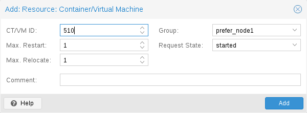
The above config was generated using the ha-manager command-line tool:
# ha-manager add vm:501 --state started --max_relocate 2
# ha-manager add ct:102
15.6.2. Groups
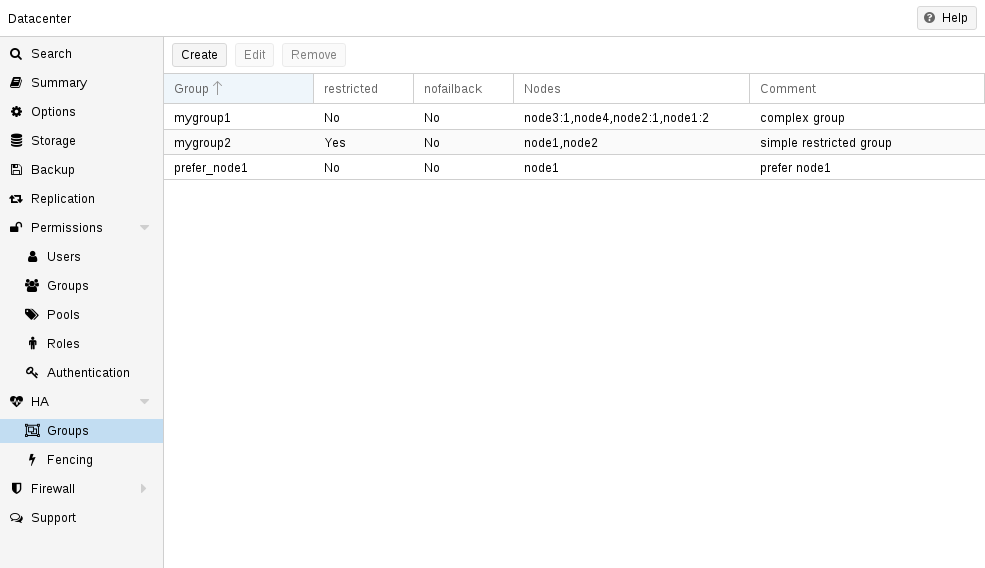
The HA group configuration file /etc/pve/ha/groups.cfg is used to define groups of cluster nodes. A resource can be restricted to run only on the members of such group. A group configuration look like this:
group: <group>
       nodes <node_list>
       <property> <value>
       ...
- comment: <string>
-
Description.
- nodes: <node>[:<pri>]{,<node>[:<pri>]}*
-
List of cluster node members, where a priority can be given to each node. A resource bound to a group will run on the available nodes with the highest priority. If there are more nodes in the highest priority class, the services will get distributed to those nodes. The priorities have a relative meaning only.
- nofailback: <boolean> (default = 0)
-
The CRM tries to run services on the node with the highest priority. If a node with higher priority comes online, the CRM migrates the service to that node. Enabling nofailback prevents that behavior.
- restricted: <boolean> (default = 0)
-
Resources bound to restricted groups may only run on nodes defined by the group. The resource will be placed in the stopped state if no group node member is online. Resources on unrestricted groups may run on any cluster node if all group members are offline, but they will migrate back as soon as a group member comes online. One can implement a preferred node behavior using an unrestricted group with only one member.
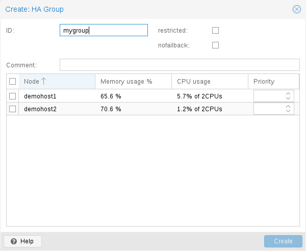
A common requirement is that a resource should run on a specific node. Usually the resource is able to run on other nodes, so you can define an unrestricted group with a single member:
# ha-manager groupadd prefer_node1 --nodes node1
For bigger clusters, it makes sense to define a more detailed failover behavior. For example, you may want to run a set of services on node1 if possible. If node1 is not available, you want to run them equally split on node2 and node3. If those nodes also fail, the services should run on node4. To achieve this you could set the node list to:
# ha-manager groupadd mygroup1 -nodes "node1:2,node2:1,node3:1,node4"
Another use case is if a resource uses other resources only available on specific nodes, lets say node1 and node2. We need to make sure that HA manager does not use other nodes, so we need to create a restricted group with said nodes:
# ha-manager groupadd mygroup2 -nodes "node1,node2" -restricted
The above commands created the following group configuration file:
group: prefer_node1
       nodes node1

group: mygroup1
       nodes node2:1,node4,node1:2,node3:1

group: mygroup2
       nodes node2,node1
       restricted 1
The nofailback options is mostly useful to avoid unwanted resource movements during administration tasks. For example, if you need to migrate a service to a node which doesn’t have the highest priority in the group, you need to tell the HA manager not to instantly move this service back by setting the nofailback option.
Another scenario is when a service was fenced and it got recovered to another node. The admin tries to repair the fenced node and brings it up online again to investigate the cause of failure and check if it runs stably again. Setting the nofailback flag prevents the recovered services from moving straight back to the fenced node.
15.7. Fencing
On node failures, fencing ensures that the erroneous node is guaranteed to be offline. This is required to make sure that no resource runs twice when it gets recovered on another node. This is a really important task, because without this, it would not be possible to recover a resource on another node.
If a node did not get fenced, it would be in an unknown state where it may have still access to shared resources. This is really dangerous! Imagine that every network but the storage one broke. Now, while not reachable from the public network, the VM still runs and writes to the shared storage.
If we then simply start up this VM on another node, we would get a dangerous race condition, because we write from both nodes. Such conditions can destroy all VM data and the whole VM could be rendered unusable. The recovery could also fail if the storage protects against multiple mounts.
15.7.1. How Proxmox VE Fences
There are different methods to fence a node, for example, fence devices which cut off the power from the node or disable their communication completely. Those are often quite expensive and bring additional critical components into a system, because if they fail you cannot recover any service.
We thus wanted to integrate a simpler fencing method, which does not require additional external hardware. This can be done using watchdog timers.
-
external power switches
-
isolate nodes by disabling complete network traffic on the switch
-
self fencing using watchdog timers
Watchdog timers have been widely used in critical and dependable systems since the beginning of microcontrollers. They are often simple, independent integrated circuits which are used to detect and recover from computer malfunctions.
During normal operation, ha-manager regularly resets the watchdog timer to prevent it from elapsing. If, due to a hardware fault or program error, the computer fails to reset the watchdog, the timer will elapse and trigger a reset of the whole server (reboot).
Recent server motherboards often include such hardware watchdogs, but these need to be configured. If no watchdog is available or configured, we fall back to the Linux Kernel softdog. While still reliable, it is not independent of the servers hardware, and thus has a lower reliability than a hardware watchdog.
15.7.2. Configure Hardware Watchdog
By default, all hardware watchdog modules are blocked for security reasons. They are like a loaded gun if not correctly initialized. To enable a hardware watchdog, you need to specify the module to load in /etc/default/pve-ha-manager, for example:
# select watchdog module (default is softdog)
WATCHDOG_MODULE=iTCO_wdt
This configuration is read by the watchdog-mux service, which loads the specified module at startup.
15.7.3. Recover Fenced Services
After a node failed and its fencing was successful, the CRM tries to move services from the failed node to nodes which are still online.
The selection of nodes, on which those services gets recovered, is influenced by the resource group settings, the list of currently active nodes, and their respective active service count.
The CRM first builds a set out of the intersection between user selected nodes (from group setting) and available nodes. It then choose the subset of nodes with the highest priority, and finally select the node with the lowest active service count. This minimizes the possibility of an overloaded node.
|
|
On node failure, the CRM distributes services to the remaining nodes. This increases the service count on those nodes, and can lead to high load, especially on small clusters. Please design your cluster so that it can handle such worst case scenarios. |
15.8. Start Failure Policy
The start failure policy comes into effect if a service failed to start on a node one or more times. It can be used to configure how often a restart should be triggered on the same node and how often a service should be relocated, so that it has an attempt to be started on another node. The aim of this policy is to circumvent temporary unavailability of shared resources on a specific node. For example, if a shared storage isn’t available on a quorate node anymore, for instance due to network problems, but is still available on other nodes, the relocate policy allows the service to start nonetheless.
There are two service start recover policy settings which can be configured specific for each resource.
- max_restart
-
Maximum number of attempts to restart a failed service on the actual node. The default is set to one.
- max_relocate
-
Maximum number of attempts to relocate the service to a different node. A relocate only happens after the max_restart value is exceeded on the actual node. The default is set to one.
|
|
The relocate count state will only reset to zero when the service had at least one successful start. That means if a service is re-started without fixing the error only the restart policy gets repeated. |
15.9. Error Recovery
If, after all attempts, the service state could not be recovered, it gets placed in an error state. In this state, the service won’t get touched by the HA stack anymore. The only way out is disabling a service:
# ha-manager set vm:100 --state disabled
This can also be done in the web interface.
To recover from the error state you should do the following:
-
bring the resource back into a safe and consistent state (e.g.: kill its process if the service could not be stopped)
-
disable the resource to remove the error flag
-
fix the error which led to this failures
-
after you fixed all errors you may request that the service starts again
15.10. Package Updates
When updating the ha-manager, you should do one node after the other, never all at once for various reasons. First, while we test our software thoroughly, a bug affecting your specific setup cannot totally be ruled out. Updating one node after the other and checking the functionality of each node after finishing the update helps to recover from eventual problems, while updating all at once could result in a broken cluster and is generally not good practice.
Also, the Proxmox VE HA stack uses a request acknowledge protocol to perform actions between the cluster and the local resource manager. For restarting, the LRM makes a request to the CRM to freeze all its services. This prevents them from getting touched by the Cluster during the short time the LRM is restarting. After that, the LRM may safely close the watchdog during a restart. Such a restart happens normally during a package update and, as already stated, an active master CRM is needed to acknowledge the requests from the LRM. If this is not the case the update process can take too long which, in the worst case, may result in a reset triggered by the watchdog.
15.11. Node Maintenance
Sometimes it is necessary to perform maintenance on a node, such as replacing hardware or simply installing a new kernel image. This also applies while the HA stack is in use.
The HA stack can support you mainly in two types of maintenance:
-
for general shutdowns or reboots, the behavior can be configured, see Shutdown Policy.
-
for maintenance that does not require a shutdown or reboot, or that should not be switched off automatically after only one reboot, you can enable the manual maintenance mode.
15.11.1. Maintenance Mode
You can use the manual maintenance mode to mark the node as unavailable for HA operation, prompting all services managed by HA to migrate to other nodes.
The target nodes for these migrations are selected from the other currently available nodes, and determined by the HA group configuration and the configured cluster resource scheduler (CRS) mode. During each migration, the original node will be recorded in the HA managers' state, so that the service can be moved back again automatically once the maintenance mode is disabled and the node is back online.
Currently you can enabled or disable the maintenance mode using the ha-manager CLI tool.
# ha-manager crm-command node-maintenance enable NODENAME
This will queue a CRM command, when the manager processes this command it will record the request for maintenance-mode in the manager status. This allows you to submit the command on any node, not just on the one you want to place in, or out of the maintenance mode.
Once the LRM on the respective node picks the command up it will mark itself as unavailable, but still process all migration commands. This means that the LRM self-fencing watchdog will stay active until all active services got moved, and all running workers finished.
Note that the LRM status will read maintenance mode as soon as the LRM picked the requested state up, not only when all services got moved away, this user experience is planned to be improved in the future. For now, you can check for any active HA service left on the node, or watching out for a log line like: pve-ha-lrm[PID]: watchdog closed (disabled) to know when the node finished its transition into the maintenance mode.
|
|
The manual maintenance mode is not automatically deleted on node reboot, but only if it is either manually deactivated using the ha-manager CLI or if the manager-status is manually cleared. |
# ha-manager crm-command node-maintenance disable NODENAME
The process of disabling the manual maintenance mode is similar to enabling it. Using the ha-manager CLI command shown above will queue a CRM command that, once processed, marks the respective LRM node as available again.
If you deactivate the maintenance mode, all services that were on the node when the maintenance mode was activated will be moved back.
15.11.2. Shutdown Policy
Below you will find a description of the different HA policies for a node shutdown. Currently Conditional is the default due to backward compatibility. Some users may find that Migrate behaves more as expected.
The shutdown policy can be configured in the Web UI (Datacenter → Options → HA Settings), or directly in datacenter.cfg:
ha: shutdown_policy=<value>
Migrate
Once the Local Resource manager (LRM) gets a shutdown request and this policy is enabled, it will mark itself as unavailable for the current HA manager. This triggers a migration of all HA Services currently located on this node. The LRM will try to delay the shutdown process, until all running services get moved away. But, this expects that the running services can be migrated to another node. In other words, the service must not be locally bound, for example by using hardware passthrough. As non-group member nodes are considered as runnable target if no group member is available, this policy can still be used when making use of HA groups with only some nodes selected. But, marking a group as restricted tells the HA manager that the service cannot run outside of the chosen set of nodes. If all of those nodes are unavailable, the shutdown will hang until you manually intervene. Once the shut down node comes back online again, the previously displaced services will be moved back, if they were not already manually migrated in-between.
|
|
The watchdog is still active during the migration process on shutdown. If the node loses quorum it will be fenced and the services will be recovered. |
If you start a (previously stopped) service on a node which is currently being maintained, the node needs to be fenced to ensure that the service can be moved and started on another available node.
Failover
This mode ensures that all services get stopped, but that they will also be recovered, if the current node is not online soon. It can be useful when doing maintenance on a cluster scale, where live-migrating VMs may not be possible if too many nodes are powered off at a time, but you still want to ensure HA services get recovered and started again as soon as possible.
Freeze
This mode ensures that all services get stopped and frozen, so that they won’t get recovered until the current node is online again.
Conditional
The Conditional shutdown policy automatically detects if a shutdown or a reboot is requested, and changes behaviour accordingly.
A shutdown (poweroff) is usually done if it is planned for the node to stay down for some time. The LRM stops all managed services in this case. This means that other nodes will take over those services afterwards.
|
|
Recent hardware has large amounts of memory (RAM). So we stop all resources, then restart them to avoid online migration of all that RAM. If you want to use online migration, you need to invoke that manually before you shutdown the node. |
Node reboots are initiated with the reboot command. This is usually done after installing a new kernel. Please note that this is different from “shutdown”, because the node immediately starts again.
The LRM tells the CRM that it wants to restart, and waits until the CRM puts all resources into the freeze state (same mechanism is used for Package Updates). This prevents those resources from being moved to other nodes. Instead, the CRM starts the resources after the reboot on the same node.
Manual Resource Movement
Last but not least, you can also manually move resources to other nodes, before you shutdown or restart a node. The advantage is that you have full control, and you can decide if you want to use online migration or not.
|
|
Please do not kill services like pve-ha-crm, pve-ha-lrm or watchdog-mux. They manage and use the watchdog, so this can result in an immediate node reboot or even reset. |
15.12. Cluster Resource Scheduling
The cluster resource scheduler (CRS) mode controls how HA selects nodes for the recovery of a service as well as for migrations that are triggered by a shutdown policy. The default mode is basic, you can change it in the Web UI (Datacenter → Options), or directly in datacenter.cfg:
crs: ha=static
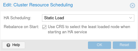
The change will be in effect starting with the next manager round (after a few seconds).
For each service that needs to be recovered or migrated, the scheduler iteratively chooses the best node among the nodes with the highest priority in the service’s group.
|
|
There are plans to add modes for (static and dynamic) load-balancing in the future. |
15.12.1. Basic Scheduler
The number of active HA services on each node is used to choose a recovery node. Non-HA-managed services are currently not counted.
15.12.2. Static-Load Scheduler
|
|
The static mode is still a technology preview. |
Static usage information from HA services on each node is used to choose a recovery node. Usage of non-HA-managed services is currently not considered.
For this selection, each node in turn is considered as if the service was already running on it, using CPU and memory usage from the associated guest configuration. Then for each such alternative, CPU and memory usage of all nodes are considered, with memory being weighted much more, because it’s a truly limited resource. For both, CPU and memory, highest usage among nodes (weighted more, as ideally no node should be overcommitted) and average usage of all nodes (to still be able to distinguish in case there already is a more highly committed node) are considered.
|
|
The more services the more possible combinations there are, so it’s currently not recommended to use it if you have thousands of HA managed services. |
15.12.3. CRS Scheduling Points
The CRS algorithm is not applied for every service in every round, since this would mean a large number of constant migrations. Depending on the workload, this could put more strain on the cluster than could be avoided by constant balancing. That’s why the Proxmox VE HA manager favors keeping services on their current node.
The CRS is currently used at the following scheduling points:
-
Service recovery (always active). When a node with active HA services fails, all its services need to be recovered to other nodes. The CRS algorithm will be used here to balance that recovery over the remaining nodes.
-
HA group config changes (always active). If a node is removed from a group, or its priority is reduced, the HA stack will use the CRS algorithm to find a new target node for the HA services in that group, matching the adapted priority constraints.
-
HA service stopped → start transtion (opt-in). Requesting that a stopped service should be started is an good opportunity to check for the best suited node as per the CRS algorithm, as moving stopped services is cheaper to do than moving them started, especially if their disk volumes reside on shared storage. You can enable this by setting the ha-rebalance-on-start CRS option in the datacenter config. You can change that option also in the Web UI, under Datacenter → Options → Cluster Resource Scheduling.
16. Backup and Restore
Backups are a requirement for any sensible IT deployment, and Proxmox VE provides a fully integrated solution, using the capabilities of each storage and each guest system type. This allows the system administrator to fine tune via the mode option between consistency of the backups and downtime of the guest system.
Proxmox VE backups are always full backups - containing the VM/CT configuration and all data. Backups can be started via the GUI or via the vzdump command-line tool.
Before a backup can run, a backup storage must be defined. Refer to the storage documentation on how to add a storage. It can either be a Proxmox Backup Server storage, where backups are stored as de-duplicated chunks and metadata, or a file-level storage, where backups are stored as regular files. Using Proxmox Backup Server on a dedicated host is recommended, because of its advanced features. Using an NFS server is a good alternative. In both cases, you might want to save those backups later to a tape drive, for off-site archiving.
Backup jobs can be scheduled so that they are executed automatically on specific days and times, for selectable nodes and guest systems. See the Backup Jobs section for more.
16.1. Backup Modes
There are several ways to provide consistency (option mode), depending on the guest type.
- stop mode
-
This mode provides the highest consistency of the backup, at the cost of a short downtime in the VM operation. It works by executing an orderly shutdown of the VM, and then runs a background QEMU process to backup the VM data. After the backup is started, the VM goes to full operation mode if it was previously running. Consistency is guaranteed by using the live backup feature.
- suspend mode
-
This mode is provided for compatibility reason, and suspends the VM before calling the snapshot mode. Since suspending the VM results in a longer downtime and does not necessarily improve the data consistency, the use of the snapshot mode is recommended instead.
- snapshot mode
-
This mode provides the lowest operation downtime, at the cost of a small inconsistency risk. It works by performing a Proxmox VE live backup, in which data blocks are copied while the VM is running. If the guest agent is enabled (agent: 1) and running, it calls guest-fsfreeze-freeze and guest-fsfreeze-thaw to improve consistency.
A technical overview of the Proxmox VE live backup for QemuServer can be found online here.
|
|
Proxmox VE live backup provides snapshot-like semantics on any storage type. It does not require that the underlying storage supports snapshots. Also please note that since the backups are done via a background QEMU process, a stopped VM will appear as running for a short amount of time while the VM disks are being read by QEMU. However the VM itself is not booted, only its disk(s) are read. |
- stop mode
-
Stop the container for the duration of the backup. This potentially results in a very long downtime.
- suspend mode
-
This mode uses rsync to copy the container data to a temporary location (see option --tmpdir). Then the container is suspended and a second rsync copies changed files. After that, the container is started (resumed) again. This results in minimal downtime, but needs additional space to hold the container copy.
When the container is on a local file system and the target storage of the backup is an NFS/CIFS server, you should set --tmpdir to reside on a local file system too, as this will result in a many fold performance improvement. Use of a local tmpdir is also required if you want to backup a local container using ACLs in suspend mode if the backup storage is an NFS server.
- snapshot mode
-
This mode uses the snapshotting facilities of the underlying storage. First, the container will be suspended to ensure data consistency. A temporary snapshot of the container’s volumes will be made and the snapshot content will be archived in a tar file. Finally, the temporary snapshot is deleted again.
|
|
snapshot mode requires that all backed up volumes are on a storage that supports snapshots. Using the backup=no mount point option individual volumes can be excluded from the backup (and thus this requirement). |
|
|
By default additional mount points besides the Root Disk mount point are not included in backups. For volume mount points you can set the Backup option to include the mount point in the backup. Device and bind mounts are never backed up as their content is managed outside the Proxmox VE storage library. |
16.1.1. VM Backup Fleecing
When a backup for a VM is started, QEMU will install a "copy-before-write" filter in its block layer. This filter ensures that upon new guest writes, old data still needed for the backup is sent to the backup target first. The guest write blocks until this operation is finished so guest IO to not-yet-backed-up sectors will be limited by the speed of the backup target.
With backup fleecing, such old data is cached in a fleecing image rather than sent directly to the backup target. This can help guest IO performance and even prevent hangs in certain scenarios, at the cost of requiring more storage space. Use e.g. vzdump 123 --fleecing enabled=1,storage=local-lvm to enable backup fleecing, with fleecing images created on the storage local-lvm.
The fleecing storage should be a fast local storage, with thin provisioning and discard support. Examples are LVM-thin, RBD, ZFS with sparse 1 in the storage configuration, many file-based storages. Ideally, the fleecing storage is a dedicated storage, so it running full will not affect other guests and just fail the backup. Parts of the fleecing image that have been backed up will be discarded to try and keep the space usage low.
For file-based storages that do not support discard (e.g. NFS before version 4.2), you should set preallocation off in the storage configuration. In combination with qcow2 (used automatically as the format for the fleecing image when the storage supports it), this has the advantage that already allocated parts of the image can be re-used later, which can still help save quite a bit of space.
|
|
On a storage that’s not thinly provisioned, e.g. LVM or ZFS without the sparse option, the full size of the original disk needs to be reserved for the fleecing image up-front. On a thinly provisioned storage, the fleecing image can grow to the same size as the original image only if the guest re-writes a whole disk while the backup is busy with another disk. |
16.2. Backup File Names
Newer versions of vzdump encode the guest type and the backup time into the filename, for example
vzdump-lxc-105-2009_10_09-11_04_43.tar
That way it is possible to store several backup in the same directory. You can limit the number of backups that are kept with various retention options, see the Backup Retention section below.
16.3. Backup File Compression
The backup file can be compressed with one of the following algorithms: lzo
[Lempel–Ziv–Oberhumer a lossless data compression algorithm
https://en.wikipedia.org/wiki/Lempel-Ziv-Oberhumer]
, gzip
[gzip -
based on the DEFLATE algorithm https://en.wikipedia.org/wiki/Gzip]
or zstd
[Zstandard a lossless data compression algorithm
https://en.wikipedia.org/wiki/Zstandard]
.
Currently, Zstandard (zstd) is the fastest of these three algorithms. Multi-threading is another advantage of zstd over lzo and gzip. Lzo and gzip are more widely used and often installed by default.
You can install pigz
[pigz - parallel implementation of gzip
https://zlib.net/pigz/]
as a drop-in replacement for gzip to provide better
performance due to multi-threading. For pigz & zstd, the amount of
threads/cores can be adjusted. See the
configuration options below.
The extension of the backup file name can usually be used to determine which compression algorithm has been used to create the backup.
.zst |
Zstandard (zstd) compression |
.gz or .tgz |
gzip compression |
.lzo |
lzo compression |
If the backup file name doesn’t end with one of the above file extensions, then it was not compressed by vzdump.
16.4. Backup Encryption
For Proxmox Backup Server storages, you can optionally set up client-side encryption of backups, see the corresponding section.
16.5. Backup Jobs
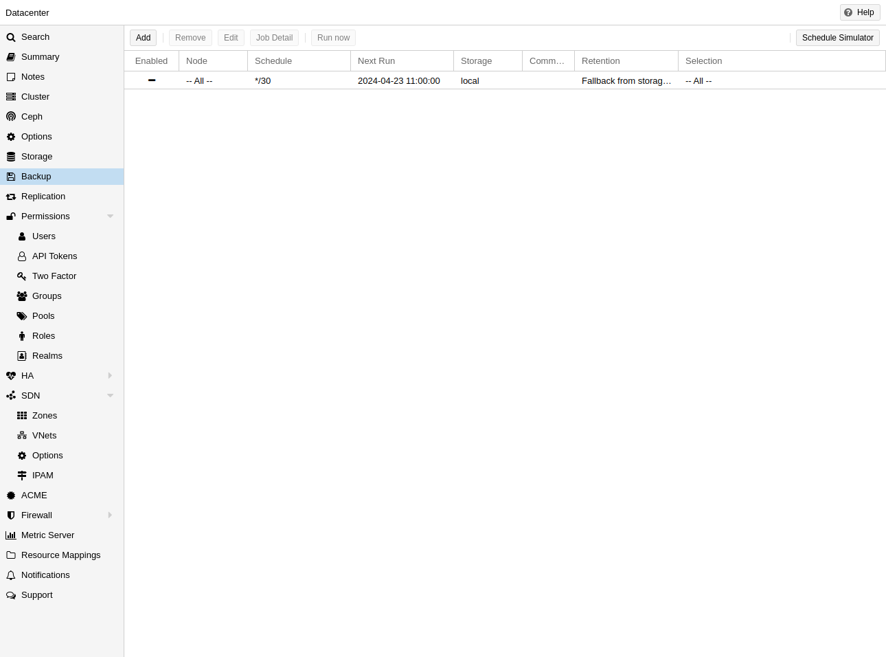
Besides triggering a backup manually, you can also setup periodic jobs that backup all, or a selection of virtual guest to a storage. You can manage the jobs in the UI under Datacenter → Backup or via the /cluster/backup API endpoint. Both will generate job entries in /etc/pve/jobs.cfg, which are parsed and executed by the pvescheduler daemon.
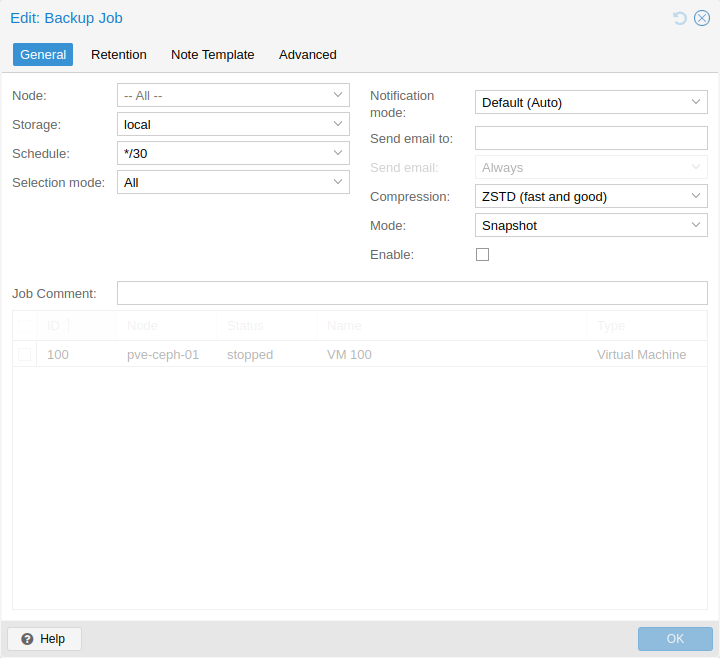
A job is either configured for all cluster nodes or a specific node, and is executed according to a given schedule. The format for the schedule is very similar to systemd calendar events, see the calendar events section for details. The Schedule field in the UI can be freely edited, and it contains several examples that can be used as a starting point in its drop-down list.
You can configure job-specific retention options overriding those from the storage or node configuration, as well as a template for notes for additional information to be saved together with the backup.
Since scheduled backups miss their execution when the host was offline or the pvescheduler was disabled during the scheduled time, it is possible to configure the behaviour for catching up. By enabling the Repeat missed option (in the Advanced tab in the UI, repeat-missed in the config), you can tell the scheduler that it should run missed jobs as soon as possible.
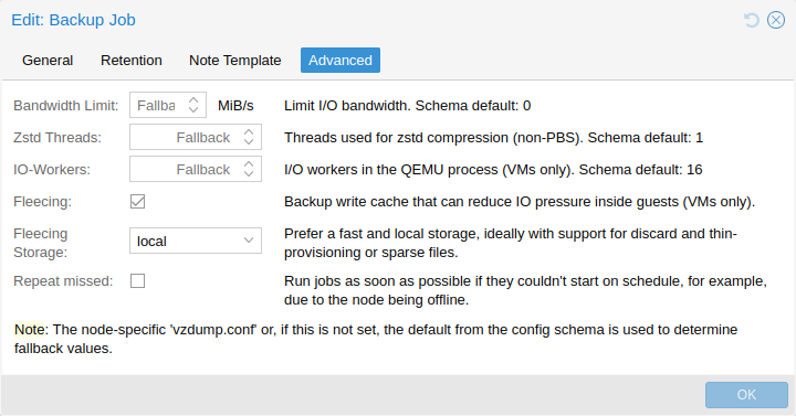
There are a few settings for tuning backup performance (some of which are exposed in the Advanced tab in the UI). The most notable is bwlimit for limiting IO bandwidth. The amount of threads used for the compressor can be controlled with the pigz (replacing gzip), respectively, zstd setting. Furthermore, there are ionice (when the BFQ scheduler is used) and, as part of the performance setting, max-workers (affects VM backups only) and pbs-entries-max (affects container backups only). See the configuration options for details.
16.6. Backup Retention
With the prune-backups option you can specify which backups you want to keep in a flexible manner.
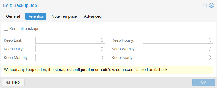
The following retention options are available:
- keep-all <boolean>
-
Keep all backups. If this is true, no other options can be set.
- keep-last <N>
-
Keep the last <N> backups.
- keep-hourly <N>
-
Keep backups for the last <N> hours. If there is more than one backup for a single hour, only the latest is kept.
- keep-daily <N>
-
Keep backups for the last <N> days. If there is more than one backup for a single day, only the latest is kept.
- keep-weekly <N>
-
Keep backups for the last <N> weeks. If there is more than one backup for a single week, only the latest is kept.
|
|
Weeks start on Monday and end on Sunday. The software uses the ISO week date-system and handles weeks at the end of the year correctly. |
- keep-monthly <N>
-
Keep backups for the last <N> months. If there is more than one backup for a single month, only the latest is kept.
- keep-yearly <N>
-
Keep backups for the last <N> years. If there is more than one backup for a single year, only the latest is kept.
The retention options are processed in the order given above. Each option only covers backups within its time period. The next option does not take care of already covered backups. It will only consider older backups.
Specify the retention options you want to use as a comma-separated list, for example:
# vzdump 777 --prune-backups keep-last=3,keep-daily=13,keep-yearly=9
While you can pass prune-backups directly to vzdump, it is often more sensible to configure the setting on the storage level, which can be done via the web interface.
|
|
The old maxfiles option is deprecated and should be replaced either by keep-last or, in case maxfiles was 0 for unlimited retention, by keep-all. |
16.6.1. Prune Simulator
You can use the prune simulator of the Proxmox Backup Server documentation to explore the effect of different retention options with various backup schedules.
16.6.2. Retention Settings Example
The backup frequency and retention of old backups may depend on how often data changes, and how important an older state may be, in a specific work load. When backups act as a company’s document archive, there may also be legal requirements for how long backups must be kept.
For this example, we assume that you are doing daily backups, have a retention period of 10 years, and the period between backups stored gradually grows.
keep-last=3 - even if only daily backups are taken, an admin may want to create an extra one just before or after a big upgrade. Setting keep-last ensures this.
keep-hourly is not set - for daily backups this is not relevant. You cover extra manual backups already, with keep-last.
keep-daily=13 - together with keep-last, which covers at least one day, this ensures that you have at least two weeks of backups.
keep-weekly=8 - ensures that you have at least two full months of weekly backups.
keep-monthly=11 - together with the previous keep settings, this ensures that you have at least a year of monthly backups.
keep-yearly=9 - this is for the long term archive. As you covered the current year with the previous options, you would set this to nine for the remaining ones, giving you a total of at least 10 years of coverage.
We recommend that you use a higher retention period than is minimally required by your environment; you can always reduce it if you find it is unnecessarily high, but you cannot recreate backups once they have been removed.
16.7. Backup Protection
You can mark a backup as protected to prevent its removal. Attempting to remove a protected backup via Proxmox VE’s UI, CLI or API will fail. However, this is enforced by Proxmox VE and not the file-system, that means that a manual removal of a backup file itself is still possible for anyone with write access to the underlying backup storage.
|
|
Protected backups are ignored by pruning and do not count towards the retention settings. |
For filesystem-based storages, the protection is implemented via a sentinel file <backup-name>.protected. For Proxmox Backup Server, it is handled on the server side (available since Proxmox Backup Server version 2.1).
Use the storage option max-protected-backups to control how many protected backups per guest are allowed on the storage. Use -1 for unlimited. The default is unlimited for users with Datastore.Allocate privilege and 5 for other users.
16.8. Backup Notes
You can add notes to backups using the Edit Notes button in the UI or via the storage content API.
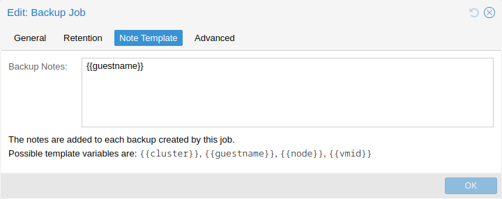
It is also possible to specify a template for generating notes dynamically for a backup job and for manual backup. The template string can contain variables, surrounded by two curly braces, which will be replaced by the corresponding value when the backup is executed.
Currently supported are:
-
{{cluster}} the cluster name, if any
-
{{guestname}} the virtual guest’s assigned name
-
{{node}} the host name of the node the backup is being created
-
{{vmid}} the numerical VMID of the guest
When specified via API or CLI, it needs to be a single line, where newline and backslash need to be escaped as literal \n and \\ respectively.
16.9. Restore
A backup archive can be restored through the Proxmox VE web GUI or through the following CLI tools:
- pct restore
-
Container restore utility
- qmrestore
-
Virtual Machine restore utility
For details see the corresponding manual pages.
16.9.1. Bandwidth Limit
Restoring one or more big backups may need a lot of resources, especially storage bandwidth for both reading from the backup storage and writing to the target storage. This can negatively affect other virtual guests as access to storage can get congested.
To avoid this you can set bandwidth limits for a backup job. Proxmox VE implements two kinds of limits for restoring and archive:
-
per-restore limit: denotes the maximal amount of bandwidth for reading from a backup archive
-
per-storage write limit: denotes the maximal amount of bandwidth used for writing to a specific storage
The read limit indirectly affects the write limit, as we cannot write more than we read. A smaller per-job limit will overwrite a bigger per-storage limit. A bigger per-job limit will only overwrite the per-storage limit if you have ‘Data.Allocate’ permissions on the affected storage.
You can use the ‘--bwlimit <integer>` option from the restore CLI commands to set up a restore job specific bandwidth limit. KiB/s is used as unit for the limit, this means passing `10240’ will limit the read speed of the backup to 10 MiB/s, ensuring that the rest of the possible storage bandwidth is available for the already running virtual guests, and thus the backup does not impact their operations.
|
|
You can use ‘0` for the bwlimit parameter to disable all limits for a specific restore job. This can be helpful if you need to restore a very important virtual guest as fast as possible. (Needs `Data.Allocate’ permissions on storage) |
Most times your storage’s generally available bandwidth stays the same over time, thus we implemented the possibility to set a default bandwidth limit per configured storage, this can be done with:
# pvesm set STORAGEID --bwlimit restore=KIBs
16.9.2. Live-Restore
Restoring a large backup can take a long time, in which a guest is still unavailable. For VM backups stored on a Proxmox Backup Server, this wait time can be mitigated using the live-restore option.
Enabling live-restore via either the checkbox in the GUI or the --live-restore argument of qmrestore causes the VM to start as soon as the restore begins. Data is copied in the background, prioritizing chunks that the VM is actively accessing.
Note that this comes with two caveats:
-
During live-restore, the VM will operate with limited disk read speeds, as data has to be loaded from the backup server (once loaded, it is immediately available on the destination storage however, so accessing data twice only incurs the penalty the first time). Write speeds are largely unaffected.
-
If the live-restore fails for any reason, the VM will be left in an undefined state - that is, not all data might have been copied from the backup, and it is most likely not possible to keep any data that was written during the failed restore operation.
This mode of operation is especially useful for large VMs, where only a small amount of data is required for initial operation, e.g. web servers - once the OS and necessary services have been started, the VM is operational, while the background task continues copying seldom used data.
16.9.3. Single File Restore
The File Restore button in the Backups tab of the storage GUI can be used to open a file browser directly on the data contained in a backup. This feature is only available for backups on a Proxmox Backup Server.
For containers, the first layer of the file tree shows all included pxar archives, which can be opened and browsed freely. For VMs, the first layer shows contained drive images, which can be opened to reveal a list of supported storage technologies found on the drive. In the most basic case, this will be an entry called part, representing a partition table, which contains entries for each partition found on the drive. Note that for VMs, not all data might be accessible (unsupported guest file systems, storage technologies, etc…).
Files and directories can be downloaded using the Download button, the latter being compressed into a zip archive on the fly.
To enable secure access to VM images, which might contain untrusted data, a temporary VM (not visible as a guest) is started. This does not mean that data downloaded from such an archive is inherently safe, but it avoids exposing the hypervisor system to danger. The VM will stop itself after a timeout. This entire process happens transparently from a user’s point of view.
|
|
For troubleshooting purposes, each temporary VM instance generates a log file in /var/log/proxmox-backup/file-restore/. The log file might contain additional information in case an attempt to restore individual files or accessing file systems contained in a backup archive fails. |
16.10. Configuration
Global configuration is stored in /etc/vzdump.conf. The file uses a simple colon separated key/value format. Each line has the following format:
OPTION: value
Blank lines in the file are ignored, and lines starting with a # character are treated as comments and are also ignored. Values from this file are used as default, and can be overwritten on the command line.
We currently support the following options:
- bwlimit: <integer> (0 - N) (default = 0)
-
Limit I/O bandwidth (in KiB/s).
- compress: <0 | 1 | gzip | lzo | zstd> (default = 0)
-
Compress dump file.
- dumpdir: <string>
-
Store resulting files to specified directory.
- exclude-path: <array>
-
Exclude certain files/directories (shell globs). Paths starting with / are anchored to the container’s root, other paths match relative to each subdirectory.
- fleecing: [[enabled=]<1|0>] [,storage=<storage ID>]
-
Options for backup fleecing (VM only).
- enabled=<boolean> (default = 0)
-
Enable backup fleecing. Cache backup data from blocks where new guest writes happen on specified storage instead of copying them directly to the backup target. This can help guest IO performance and even prevent hangs, at the cost of requiring more storage space.
- storage=<storage ID>
-
Use this storage to storage fleecing images. For efficient space usage, it’s best to use a local storage that supports discard and either thin provisioning or sparse files.
- ionice: <integer> (0 - 8) (default = 7)
-
Set IO priority when using the BFQ scheduler. For snapshot and suspend mode backups of VMs, this only affects the compressor. A value of 8 means the idle priority is used, otherwise the best-effort priority is used with the specified value.
- lockwait: <integer> (0 - N) (default = 180)
-
Maximal time to wait for the global lock (minutes).
- mailnotification: <always | failure> (default = always)
-
Deprecated: use notification targets/matchers instead. Specify when to send a notification mail
- mailto: <string>
-
Deprecated: Use notification targets/matchers instead. Comma-separated list of email addresses or users that should receive email notifications.
- maxfiles: <integer> (1 - N)
-
Deprecated: use prune-backups instead. Maximal number of backup files per guest system.
- mode: <snapshot | stop | suspend> (default = snapshot)
-
Backup mode.
- notes-template: <string>
-
Template string for generating notes for the backup(s). It can contain variables which will be replaced by their values. Currently supported are {\{\cluster}}, {\{\guestname}}, {\{\node}}, and {\{\vmid}}, but more might be added in the future. Needs to be a single line, newline and backslash need to be escaped as \n and \\ respectively.
Requires option(s): storage - notification-mode: <auto | legacy-sendmail | notification-system> (default = auto)
-
Determine which notification system to use. If set to legacy-sendmail, vzdump will consider the mailto/mailnotification parameters and send emails to the specified address(es) via the sendmail command. If set to notification-system, a notification will be sent via PVE’s notification system, and the mailto and mailnotification will be ignored. If set to auto (default setting), an email will be sent if mailto is set, and the notification system will be used if not.
- notification-policy: <always | failure | never> (default = always)
-
Deprecated: Do not use
- notification-target: <string>
-
Deprecated: Do not use
- performance: [max-workers=<integer>] [,pbs-entries-max=<integer>]
-
Other performance-related settings.
- max-workers=<integer> (1 - 256) (default = 16)
-
Applies to VMs. Allow up to this many IO workers at the same time.
- pbs-entries-max=<integer> (1 - N) (default = 1048576)
-
Applies to container backups sent to PBS. Limits the number of entries allowed in memory at a given time to avoid unintended OOM situations. Increase it to enable backups of containers with a large amount of files.
- pigz: <integer> (default = 0)
-
Use pigz instead of gzip when N>0. N=1 uses half of cores, N>1 uses N as thread count.
- pool: <string>
-
Backup all known guest systems included in the specified pool.
- protected: <boolean>
-
If true, mark backup(s) as protected.
Requires option(s): storage - prune-backups: [keep-all=<1|0>] [,keep-daily=<N>] [,keep-hourly=<N>] [,keep-last=<N>] [,keep-monthly=<N>] [,keep-weekly=<N>] [,keep-yearly=<N>] (default = keep-all=1)
-
Use these retention options instead of those from the storage configuration.
- keep-all=<boolean>
-
Keep all backups. Conflicts with the other options when true.
- keep-daily=<N>
-
Keep backups for the last <N> different days. If there is morethan one backup for a single day, only the latest one is kept.
- keep-hourly=<N>
-
Keep backups for the last <N> different hours. If there is morethan one backup for a single hour, only the latest one is kept.
- keep-last=<N>
-
Keep the last <N> backups.
- keep-monthly=<N>
-
Keep backups for the last <N> different months. If there is morethan one backup for a single month, only the latest one is kept.
- keep-weekly=<N>
-
Keep backups for the last <N> different weeks. If there is morethan one backup for a single week, only the latest one is kept.
- keep-yearly=<N>
-
Keep backups for the last <N> different years. If there is morethan one backup for a single year, only the latest one is kept.
- remove: <boolean> (default = 1)
-
Prune older backups according to prune-backups.
- script: <string>
-
Use specified hook script.
- stdexcludes: <boolean> (default = 1)
-
Exclude temporary files and logs.
- stopwait: <integer> (0 - N) (default = 10)
-
Maximal time to wait until a guest system is stopped (minutes).
- storage: <storage ID>
-
Store resulting file to this storage.
- tmpdir: <string>
-
Store temporary files to specified directory.
- zstd: <integer> (default = 1)
-
Zstd threads. N=0 uses half of the available cores, if N is set to a value bigger than 0, N is used as thread count.
tmpdir: /mnt/fast_local_disk
storage: my_backup_storage
mode: snapshot
bwlimit: 10000
16.11. Hook Scripts
You can specify a hook script with option --script. This script is called at various phases of the backup process, with parameters accordingly set. You can find an example in the documentation directory (vzdump-hook-script.pl).
16.12. File Exclusions
|
|
this option is only available for container backups. |
vzdump skips the following files by default (disable with the option --stdexcludes 0)
/tmp/?*
/var/tmp/?*
/var/run/?*pid
You can also manually specify (additional) exclude paths, for example:
# vzdump 777 --exclude-path /tmp/ --exclude-path '/var/foo*'
excludes the directory /tmp/ and any file or directory named /var/foo, /var/foobar, and so on.
Paths that do not start with a / are not anchored to the container’s root, but will match relative to any subdirectory. For example:
# vzdump 777 --exclude-path bar
excludes any file or directory named /bar, /var/bar, /var/foo/bar, and so on, but not /bar2.
Configuration files are also stored inside the backup archive (in ./etc/vzdump/) and will be correctly restored.
16.13. Examples
Simply dump guest 777 - no snapshot, just archive the guest private area and configuration files to the default dump directory (usually /var/lib/vz/dump/).
# vzdump 777
Use rsync and suspend/resume to create a snapshot (minimal downtime).
# vzdump 777 --mode suspend
Backup all guest systems and send notification mails to root and admin. Due to mailto being set and notification-mode being set to auto by default, the notification mails are sent via the system’s sendmail command instead of the notification system.
# vzdump --all --mode suspend --mailto root --mailto admin
Use snapshot mode (no downtime) and non-default dump directory.
# vzdump 777 --dumpdir /mnt/backup --mode snapshot
Backup more than one guest (selectively)
# vzdump 101 102 103 --mailto root
Backup all guests excluding 101 and 102
# vzdump --mode suspend --exclude 101,102
Restore a container to a new CT 600
# pct restore 600 /mnt/backup/vzdump-lxc-777.tar
Restore a QemuServer VM to VM 601
# qmrestore /mnt/backup/vzdump-qemu-888.vma 601
Clone an existing container 101 to a new container 300 with a 4GB root file system, using pipes
# vzdump 101 --stdout | pct restore --rootfs 4 300 -
17. Notifications
17.1. Overview
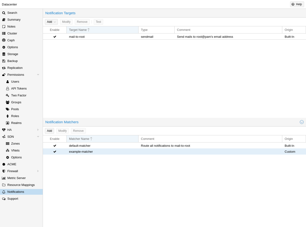
Proxmox VE will send notifications if case of noteworthy events in the system.
There are a number of different notification events, each with their own set of metadata fields that can be used in notification matchers.
A notification matcher determines which notifications shall be sent where. A matcher has match rules, that can be used to match on certain notification properties (e.g. timestamp, severity, metadata fields). If a matcher matches a notification, the notification will be routed to a configurable set of notification targets.
A notification target is an abstraction for a destination where a notification should be sent to - for instance, a Gotify server instance, or a set of email addresses. There are multiple types of notification targets, including sendmail, which uses the system’s sendmail command to send emails, or gotify, which sends a notification to a Gotify instance.
The notification system can be configured in the GUI under Datacenter → Notifications. The configuration is stored in /etc/pve/notifications.cfg and /etc/pve/priv/notifications.cfg - the latter contains sensitive configuration options such as passwords or authentication tokens for notification targets.
17.2. Notification Targets
17.2.1. Sendmail
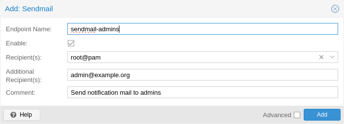
The sendmail binary is a program commonly found on Unix-like operating systems that handles the sending of email messages. It is a command-line utility that allows users and applications to send emails directly from the command line or from within scripts.
The sendmail notification target uses the sendmail binary to send emails.
|
|
In standard Proxmox VE installations, the sendmail binary is provided by Postfix. For this type of target to work correctly, it might be necessary to change Postfix’s configuration so that it can correctly deliver emails. For cluster setups it is necessary to have a working Postfix configuration on every single cluster node. |
The configuration for Sendmail target plugins has the following options:
-
mailto: E-Mail address to which the notification shall be sent to. Can be set multiple times to accomodate multiple recipients.
-
mailto-user: Users to which emails shall be sent to. The user’s email address will be looked up in users.cfg. Can be set multiple times to accomodate multiple recipients.
-
author: Sets the author of the E-Mail. Defaults to Proxmox VE.
-
from-address: Sets the from address of the E-Mail. If the parameter is not set, the plugin will fall back to the email_from setting from datacenter.cfg. If that is also not set, the plugin will default to root@$hostname, where $hostname is the hostname of the node.
-
comment: Comment for this target The From header in the email will be set to $author <$from-address>.
Example configuration (/etc/pve/notifications.cfg):
sendmail: example
        mailto-user root@pam
        mailto-user admin@pve
        mailto max@example.com
        from-address pve1@example.com
        comment Send to multiple users/addresses
17.2.2. SMTP
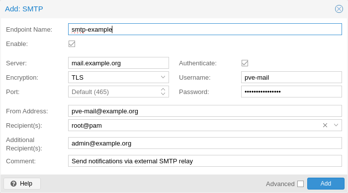
SMTP notification targets can send emails directly to an SMTP mail relay.
The configuration for SMTP target plugins has the following options:
-
mailto: E-Mail address to which the notification shall be sent to. Can be set multiple times to accomodate multiple recipients.
-
mailto-user: Users to which emails shall be sent to. The user’s email address will be looked up in users.cfg. Can be set multiple times to accomodate multiple recipients.
-
author: Sets the author of the E-Mail. Defaults to Proxmox VE.
-
from-address: Sets the From-addresss of the email. SMTP relays might require that this address is owned by the user in order to avoid spoofing. The From header in the email will be set to $author <$from-address>.
-
username: Username to use during authentication. If no username is set, no authentication will be performed. The PLAIN and LOGIN authentication methods are supported.
-
password: Password to use when authenticating.
-
mode: Sets the encryption mode (insecure, starttls or tls). Defaults to tls.
-
server: Address/IP of the SMTP relay
-
port: The port to connect to. If not set, the used port defaults to 25 (insecure), 465 (tls) or 587 (starttls), depending on the value of mode.
-
comment: Comment for this target
Example configuration (/etc/pve/notifications.cfg):
smtp: example
        mailto-user root@pam
        mailto-user admin@pve
        mailto max@example.com
        from-address pve1@example.com
        username pve1
        server mail.example.com
        mode starttls
The matching entry in /etc/pve/priv/notifications.cfg, containing the secret token:
smtp: example
        password somepassword
17.2.3. Gotify
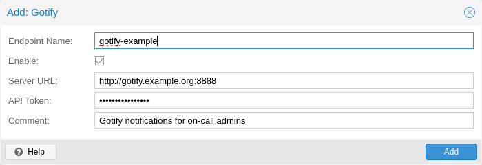
Gotify is an open-source self-hosted notification server that allows you to send and receive push notifications to various devices and applications. It provides a simple API and web interface, making it easy to integrate with different platforms and services.
The configuration for Gotify target plugins has the following options:
-
server: The base URL of the Gotify server, e.g. http://<ip>:8888
-
token: The authentication token. Tokens can be generated within the Gotify web interface.
-
comment: Comment for this target
|
|
The Gotify target plugin will respect the HTTP proxy settings from the datacenter configuration |
Example configuration (/etc/pve/notifications.cfg):
gotify: example
        server http://gotify.example.com:8888
        comment Send to multiple users/addresses
The matching entry in /etc/pve/priv/notifications.cfg, containing the secret token:
gotify: example
token somesecrettoken
17.3. Notification Matchers
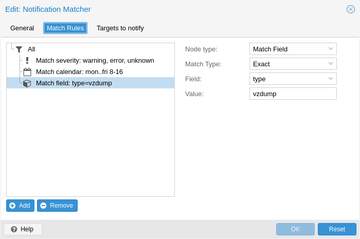
Notification matchers route notifications to notification targets based on their matching rules. These rules can match certain properties of a notification, such as the timestamp (match-calendar), the severity of the notification (match-severity) or metadata fields (match-field). If a notification is matched by a matcher, all targets configured for the matcher will receive the notification.
An arbitrary number of matchers can be created, each with with their own matching rules and targets to notify. Every target is notified at most once for every notification, even if the target is used in multiple matchers.
A matcher without any matching rules is always true; the configured targets will always be notified.
matcher: always-matches
target admin
comment This matcher always matches
17.3.1. Matcher Options
-
target: Determine which target should be notified if the matcher matches. can be used multiple times to notify multiple targets.
-
invert-match: Inverts the result of the whole matcher
-
mode: Determines how the individual match rules are evaluated to compute the result for the whole matcher. If set to all, all matching rules must match. If set to any, at least one rule must match. a matcher must be true. Defaults to all.
-
match-calendar: Match the notification’s timestamp against a schedule
-
match-field: Match the notification’s metadata fields
-
match-severity: Match the notification’s severity
-
comment: Comment for this matcher
17.3.2. Calendar Matching Rules
A calendar matcher matches the time when a notification is sent agaist a configurable schedule.
-
match-calendar 8-12
-
match-calendar 8:00-15:30
-
match-calendar mon-fri 9:00-17:00
-
match-calendar sun,tue-wed,fri 9-17
17.3.3. Field Matching Rules
Notifications have a selection of metadata fields that can be matched.
-
match-field exact:type=vzdump Only match notifications about backups.
-
match-field regex:hostname=^.+\.example\.com$ Match the hostname of the node.
If a matched metadata field does not exist, the notification will not be matched. For instance, a match-field regex:hostname=.* directive will only match notifications that have an arbitraty hostname metadata field, but will not match if the field does not exist.
17.3.4. Severity Matching Rules
A notification has a associated severity that can be matched.
-
match-severity error: Only match errors
-
match-severity warning,error: Match warnings and error
The following severities are in use: info, notice, warning, error, unknown.
17.3.5. Examples
matcher: workday
match-calendar mon-fri 9-17
target admin
comment Notify admins during working hours
matcher: night-and-weekend
match-calendar mon-fri 9-17
invert-match true
target on-call-admins
comment Separate target for non-working hours
matcher: backup-failures
match-field exact:type=vzdump
match-severity error
target backup-admins
comment Send notifications about backup failures to one group of admins
matcher: cluster-failures
match-field exact:type=replication
match-field exact:type=fencing
mode any
target cluster-admins
comment Send cluster-related notifications to other group of admins
The last matcher could also be rewritten using a field matcher with a regular expression:
matcher: cluster-failures
match-field regex:type=^(replication|fencing)$
target cluster-admins
comment Send cluster-related notifications to other group of admins
17.4. Notification Events
| Event | type | Severity | Metadata fields (in addition to type) |
|---|---|---|---|
System updates available |
package-updates |
info |
hostname |
Cluster node fenced |
fencing |
error |
hostname |
Storage replication failed |
replication |
error |
- |
Backup finished |
vzdump |
info (error on failure) |
hostname |
Mail for root |
system-mail |
unknown |
- |
| Field name | Description |
|---|---|
type |
Type of the notifcation |
hostname |
Hostname, including domain (e.g. pve1.example.com) |
17.5. System Mail Forwarding
Certain local system daemons, such as smartd, generate notification emails that are initially directed to the local root user. Proxmox VE will feed these mails into the notification system as a notification of type system-mail and with severity unknown.
When the forwarding process involves an email-based target (like sendmail or smtp), the email is forwarded exactly as received, with all original mail headers remaining intact. For all other targets, the system tries to extract both a subject line and the main text body from the email content. In instances where emails solely consist of HTML content, they will be transformed into plain text format during this process.
17.6. Permissions
In order to modify/view the configuration for notification targets, the Mapping.Modify/Mapping.Audit permissions are required for the /mapping/notifications ACL node.
Testing a target requires Mapping.Use, Mapping.Audit or Mapping.Modify permissions on /mapping/notifications
18. Important Service Daemons
18.1. pvedaemon - Proxmox VE API Daemon
This daemon exposes the whole Proxmox VE API on 127.0.0.1:85. It runs as root and has permission to do all privileged operations.
|
|
The daemon listens to a local address only, so you cannot access it from outside. The pveproxy daemon exposes the API to the outside world. |
18.2. pveproxy - Proxmox VE API Proxy Daemon
This daemon exposes the whole Proxmox VE API on TCP port 8006 using HTTPS. It runs as user www-data and has very limited permissions. Operation requiring more permissions are forwarded to the local pvedaemon.
Requests targeted for other nodes are automatically forwarded to those nodes. This means that you can manage your whole cluster by connecting to a single Proxmox VE node.
18.2.1. Host based Access Control
It is possible to configure “apache2”-like access control lists. Values are read from file /etc/default/pveproxy. For example:
ALLOW_FROM="10.0.0.1-10.0.0.5,192.168.0.0/22" DENY_FROM="all" POLICY="allow"
IP addresses can be specified using any syntax understood by Net::IP. The name all is an alias for 0/0 and ::/0 (meaning all IPv4 and IPv6 addresses).
The default policy is allow.
| Match | POLICY=deny | POLICY=allow |
|---|---|---|
Match Allow only |
allow |
allow |
Match Deny only |
deny |
deny |
No match |
deny |
allow |
Match Both Allow & Deny |
deny |
allow |
18.2.2. Listening IP Address
By default the pveproxy and spiceproxy daemons listen on the wildcard address and accept connections from both IPv4 and IPv6 clients.
By setting LISTEN_IP in /etc/default/pveproxy you can control to which IP address the pveproxy and spiceproxy daemons bind. The IP-address needs to be configured on the system.
Setting the sysctl net.ipv6.bindv6only to the non-default 1 will cause the daemons to only accept connection from IPv6 clients, while usually also causing lots of other issues. If you set this configuration we recommend to either remove the sysctl setting, or set the LISTEN_IP to 0.0.0.0 (which will only allow IPv4 clients).
LISTEN_IP can be used to only to restricting the socket to an internal interface and thus have less exposure to the public internet, for example:
LISTEN_IP="192.0.2.1"
Similarly, you can also set an IPv6 address:
LISTEN_IP="2001:db8:85a3::1"
Note that if you want to specify a link-local IPv6 address, you need to provide the interface name itself. For example:
LISTEN_IP="fe80::c463:8cff:feb9:6a4e%vmbr0"
|
|
The nodes in a cluster need access to pveproxy for communication, possibly on different sub-nets. It is not recommended to set LISTEN_IP on clustered systems. |
To apply the change you need to either reboot your node or fully restart the pveproxy and spiceproxy service:
systemctl restart pveproxy.service spiceproxy.service
|
|
Unlike reload, a restart of the pveproxy service can interrupt some long-running worker processes, for example a running console or shell from a virtual guest. So, please use a maintenance window to bring this change in effect. |
18.2.3. SSL Cipher Suite
You can define the cipher list in /etc/default/pveproxy via the CIPHERS (TLS ⇐ 1.2) and CIPHERSUITES (TLS >= 1.3) keys. For example
CIPHERS="ECDHE-ECDSA-AES256-GCM-SHA384:ECDHE-RSA-AES256-GCM-SHA384:ECDHE-ECDSA-CHACHA20-POLY1305:ECDHE-RSA-CHACHA20-POLY1305:ECDHE-ECDSA-AES128-GCM-SHA256:ECDHE-RSA-AES128-GCM-SHA256:ECDHE-ECDSA-AES256-SHA384:ECDHE-RSA-AES256-SHA384:ECDHE-ECDSA-AES128-SHA256:ECDHE-RSA-AES128-SHA256" CIPHERSUITES="TLS_AES_256_GCM_SHA384:TLS_CHACHA20_POLY1305_SHA256:TLS_AES_128_GCM_SHA256"
Above is the default. See the ciphers(1) man page from the openssl package for a list of all available options.
Additionally, you can set the client to choose the cipher used in /etc/default/pveproxy (default is the first cipher in the list available to both client and pveproxy):
HONOR_CIPHER_ORDER=0
18.2.4. Supported TLS versions
The insecure SSL versions 2 and 3 are unconditionally disabled for pveproxy. TLS versions below 1.1 are disabled by default on recent OpenSSL versions, which is honored by pveproxy (see /etc/ssl/openssl.cnf).
To disable TLS version 1.2 or 1.3, set the following in /etc/default/pveproxy:
DISABLE_TLS_1_2=1
or, respectively:
DISABLE_TLS_1_3=1
|
|
Unless there is a specific reason to do so, it is not recommended to manually adjust the supported TLS versions. |
18.2.5. Diffie-Hellman Parameters
You can define the used Diffie-Hellman parameters in /etc/default/pveproxy by setting DHPARAMS to the path of a file containing DH parameters in PEM format, for example
DHPARAMS="/path/to/dhparams.pem"
If this option is not set, the built-in skip2048 parameters will be used.
|
|
DH parameters are only used if a cipher suite utilizing the DH key exchange algorithm is negotiated. |
18.2.6. Alternative HTTPS certificate
You can change the certificate used to an external one or to one obtained via ACME.
pveproxy uses /etc/pve/local/pveproxy-ssl.pem and /etc/pve/local/pveproxy-ssl.key, if present, and falls back to /etc/pve/local/pve-ssl.pem and /etc/pve/local/pve-ssl.key. The private key may not use a passphrase.
It is possible to override the location of the certificate private key /etc/pve/local/pveproxy-ssl.key by setting TLS_KEY_FILE in /etc/default/pveproxy, for example:
TLS_KEY_FILE="/secrets/pveproxy.key"
|
|
The included ACME integration does not honor this setting. |
See the Host System Administration chapter of the documentation for details.
18.2.7. Response Compression
By default pveproxy uses gzip HTTP-level compression for compressible content, if the client supports it. This can disabled in /etc/default/pveproxy
COMPRESSION=0
18.3. pvestatd - Proxmox VE Status Daemon
This daemon queries the status of VMs, storages and containers at regular intervals. The result is sent to all nodes in the cluster.
18.4. spiceproxy - SPICE Proxy Service
SPICE (the Simple Protocol for Independent Computing Environments) is an open remote computing solution, providing client access to remote displays and devices (e.g. keyboard, mouse, audio). The main use case is to get remote access to virtual machines and container.
This daemon listens on TCP port 3128, and implements an HTTP proxy to forward CONNECT request from the SPICE client to the correct Proxmox VE VM. It runs as user www-data and has very limited permissions.
18.4.1. Host based Access Control
It is possible to configure "apache2" like access control lists. Values are read from file /etc/default/pveproxy. See pveproxy documentation for details.
18.5. pvescheduler - Proxmox VE Scheduler Daemon
This deamon is responsible for starting jobs according to the schedule, such as replication and vzdump jobs.
For vzdump jobs, it gets its configuration from the file /etc/pve/jobs.cfg
19. Useful Command-line Tools
19.1. pvesubscription - Subscription Management
This tool is used to handle Proxmox VE subscriptions.
19.2. pveperf - Proxmox VE Benchmark Script
Tries to gather some CPU/hard disk performance data on the hard disk mounted at PATH (/ is used as default):
- CPU BOGOMIPS
-
bogomips sum of all CPUs
- REGEX/SECOND
-
regular expressions per second (perl performance test), should be above 300000
- HD SIZE
-
hard disk size
- BUFFERED READS
-
simple HD read test. Modern HDs should reach at least 40 MB/sec
- AVERAGE SEEK TIME
-
tests average seek time. Fast SCSI HDs reach values < 8 milliseconds. Common IDE/SATA disks get values from 15 to 20 ms.
- FSYNCS/SECOND
-
value should be greater than 200 (you should enable write back cache mode on you RAID controller - needs a battery backed cache (BBWC)).
- DNS EXT
-
average time to resolve an external DNS name
- DNS INT
-
average time to resolve a local DNS name
19.3. Shell interface for the Proxmox VE API
The Proxmox VE management tool (pvesh) allows to directly invoke API function, without using the REST/HTTPS server.
|
|
Only root is allowed to do that. |
19.3.1. EXAMPLES
Get the list of nodes in my cluster
# pvesh get /nodes
Get a list of available options for the datacenter
# pvesh usage cluster/options -v
Set the HTMl5 NoVNC console as the default console for the datacenter
# pvesh set cluster/options -console html5
20. Frequently Asked Questions
|
|
New FAQs are appended to the bottom of this section. |
-
What distribution is Proxmox VE based on?
Proxmox VE is based on Debian GNU/Linux
-
What license does the Proxmox VE project use?
Proxmox VE code is licensed under the GNU Affero General Public License, version 3.
-
Will Proxmox VE run on a 32bit processor?
Proxmox VE works only on 64-bit CPUs (AMD or Intel). There is no plan for 32-bit for the platform.
VMs and Containers can be both 32-bit and 64-bit. -
Does my CPU support virtualization?
To check if your CPU is virtualization compatible, check for the vmx or svm tag in this command output:
egrep '(vmx|svm)' /proc/cpuinfo
-
Supported Intel CPUs
64-bit processors with Intel Virtualization Technology (Intel VT-x) support. (List of processors with Intel VT and 64-bit)
-
Supported AMD CPUs
64-bit processors with AMD Virtualization Technology (AMD-V) support.
-
What is a container/virtual environment (VE)/virtual private server (VPS)?
In the context of containers, these terms all refer to the concept of operating-system-level virtualization. Operating-system-level virtualization is a method of virtualization, in which the kernel of an operating system allows for multiple isolated instances, that all share the kernel. When referring to LXC, we call such instances containers. Because containers use the host’s kernel rather than emulating a full operating system, they require less overhead, but are limited to Linux guests.
-
What is a QEMU/KVM guest (or VM)?
A QEMU/KVM guest (or VM) is a guest system running virtualized under Proxmox VE using QEMU and the Linux KVM kernel module.
-
What is QEMU?
QEMU is a generic and open source machine emulator and virtualizer. QEMU uses the Linux KVM kernel module to achieve near native performance by executing the guest code directly on the host CPU. It is not limited to Linux guests but allows arbitrary operating systems to run.
-
How long will my Proxmox VE version be supported?
Proxmox VE versions are supported at least as long as the corresponding Debian Version is oldstable. Proxmox VE uses a rolling release model and using the latest stable version is always recommended.
Proxmox VE Version Debian Version First Release Debian EOL Proxmox EOL Proxmox VE 8
Debian 12 (Bookworm)
2023-06
tba
tba
Proxmox VE 7
Debian 11 (Bullseye)
2021-07
2024-07
2024-07
Proxmox VE 6
Debian 10 (Buster)
2019-07
2022-09
2022-09
Proxmox VE 5
Debian 9 (Stretch)
2017-07
2020-07
2020-07
Proxmox VE 4
Debian 8 (Jessie)
2015-10
2018-06
2018-06
Proxmox VE 3
Debian 7 (Wheezy)
2013-05
2016-04
2017-02
Proxmox VE 2
Debian 6 (Squeeze)
2012-04
2014-05
2014-05
Proxmox VE 1
Debian 5 (Lenny)
2008-10
2012-03
2013-01
-
How can I upgrade Proxmox VE to the next point release?
Minor version upgrades, for example upgrading from Proxmox VE in version 7.1 to 7.2 or 7.3, can be done just like any normal update. But you should still check the release notes for any relevant noteable, or breaking change.
For the update itself use either the Web UI Node → Updates panel or through the CLI with:
apt update apt full-upgrade
Always ensure you correctly setup the package repositories and only continue with the actual upgrade if apt update did not hit any error. -
How can I upgrade Proxmox VE to the next major release?
Major version upgrades, for example going from Proxmox VE 4.4 to 5.0, are also supported. They must be carefully planned and tested and should never be started without having a current backup ready.
Although the specific upgrade steps depend on your respective setup, we provide general instructions and advice of how a upgrade should be performed:
-
LXC vs LXD vs Proxmox Containers vs Docker
LXC is a userspace interface for the Linux kernel containment features. Through a powerful API and simple tools, it lets Linux users easily create and manage system containers. LXC, as well as the former OpenVZ, aims at system virtualization. Thus, it allows you to run a complete OS inside a container, where you log in using ssh, add users, run apache, etc…
LXD is built on top of LXC to provide a new, better user experience. Under the hood, LXD uses LXC through liblxc and its Go binding to create and manage the containers. It’s basically an alternative to LXC’s tools and distribution template system with the added features that come from being controllable over the network.
Proxmox Containers are how we refer to containers that are created and managed using the Proxmox Container Toolkit (pct). They also target system virtualization and use LXC as the basis of the container offering. The Proxmox Container Toolkit (pct) is tightly coupled with Proxmox VE. This means that it is aware of cluster setups, and it can use the same network and storage resources as QEMU virtual machines (VMs). You can even use the Proxmox VE firewall, create and restore backups, or manage containers using the HA framework. Everything can be controlled over the network using the Proxmox VE API.
Docker aims at running a single application in an isolated, self-contained environment. These are generally referred to as “Application Containers”, rather than “System Containers”. You manage a Docker instance from the host, using the Docker Engine command-line interface. It is not recommended to run docker directly on your Proxmox VE host.
If you want to run application containers, for example, Docker images, it is best to run them inside a Proxmox QEMU VM.
21. Bibliography
-
[Ahmed16] Wasim Ahmed. Mastering Proxmox - Third Edition. Packt Publishing, 2017. ISBN 978-1788397605
-
[Ahmed15] Wasim Ahmed. Proxmox Cookbook. Packt Publishing, 2015. ISBN 978-1783980901
-
[Cheng14] Simon M.C. Cheng. Proxmox High Availability. Packt Publishing, 2014. ISBN 978-1783980888
-
[Goldman16] Rik Goldman. Learning Proxmox VE. Packt Publishing, 2016. ISBN 978-1783981786
-
[Surber16]] Lee R. Surber. Virtualization Complete: Business Basic Edition. Linux Solutions (LRS-TEK), 2016. ASIN B01BBVQZT6
-
[Hertzog13] Raphaël Hertzog, Roland Mas., Freexian SARL The Debian Administrator's Handbook: Debian Bullseye from Discovery to Mastery, Freexian, 2021. ISBN 979-10-91414-20-3
-
[Bir96] Kenneth P. Birman. Building Secure and Reliable Network Applications. Manning Publications Co, 1996. ISBN 978-1884777295
-
[Walsh10] Norman Walsh. DocBook 5: The Definitive Guide. O’Reilly & Associates, 2010. ISBN 978-0596805029
-
[Richardson07] Leonard Richardson & Sam Ruby. RESTful Web Services. O’Reilly Media, 2007. ISBN 978-0596529260
-
[Singh15] Karan Singh. Learning Ceph. Packt Publishing, 2015. ISBN 978-1783985623
-
[Singh16] Karan Signh. Ceph Cookbook Packt Publishing, 2016. ISBN 978-1784393502
-
[Mauerer08] Wolfgang Mauerer. Professional Linux Kernel Architecture. John Wiley & Sons, 2008. ISBN 978-0470343432
-
[Loshin03] Pete Loshin, IPv6: Theory, Protocol, and Practice, 2nd Edition. Morgan Kaufmann, 2003. ISBN 978-1558608108
-
[Loeliger12] Jon Loeliger & Matthew McCullough. Version Control with Git: Powerful tools and techniques for collaborative software development. O’Reilly and Associates, 2012. ISBN 978-1449316389
-
[Kreibich10] Jay A. Kreibich. Using SQLite, O’Reilly and Associates, 2010. ISBN 978-0596521189
22. Appendix A: Command-line Interface
22.1. Output format options [FORMAT_OPTIONS]
It is possible to specify the output format using the --output-format parameter. The default format text uses ASCII-art to draw nice borders around tables. It additionally transforms some values into human-readable text, for example:
-
Unix epoch is displayed as ISO 8601 date string.
-
Durations are displayed as week/day/hour/minute/second count, i.e 1d 5h.
-
Byte sizes value include units (B, KiB, MiB, GiB, TiB, PiB).
-
Fractions are display as percentage, i.e. 1.0 is displayed as 100%.
You can also completely suppress output using option --quiet.
- --human-readable <boolean> (default = 1)
-
Call output rendering functions to produce human readable text.
- --noborder <boolean> (default = 0)
-
Do not draw borders (for text format).
- --noheader <boolean> (default = 0)
-
Do not show column headers (for text format).
- --output-format <json | json-pretty | text | yaml> (default = text)
-
Output format.
- --quiet <boolean>
-
Suppress printing results.
22.2. pvesm - Proxmox VE Storage Manager
pvesm <COMMAND> [ARGS] [OPTIONS]
pvesm add <type> <storage> [OPTIONS]
Create a new storage.
- <type>: <btrfs | cephfs | cifs | dir | esxi | glusterfs | iscsi | iscsidirect | lvm | lvmthin | nfs | pbs | rbd | zfs | zfspool>
-
Storage type.
- <storage>: <storage ID>
-
The storage identifier.
- --authsupported <string>
-
Authsupported.
- --base <string>
-
Base volume. This volume is automatically activated.
- --blocksize <string>
-
block size
- --bwlimit [clone=<LIMIT>] [,default=<LIMIT>] [,migration=<LIMIT>] [,move=<LIMIT>] [,restore=<LIMIT>]
-
Set I/O bandwidth limit for various operations (in KiB/s).
- --comstar_hg <string>
-
host group for comstar views
- --comstar_tg <string>
-
target group for comstar views
- --content <string>
-
Allowed content types.
the value rootdir is used for Containers, and value images for VMs. - --content-dirs <string>
-
Overrides for default content type directories.
- --create-base-path <boolean> (default = yes)
-
Create the base directory if it doesn’t exist.
- --create-subdirs <boolean> (default = yes)
-
Populate the directory with the default structure.
- --data-pool <string>
-
Data Pool (for erasure coding only)
- --datastore <string>
-
Proxmox Backup Server datastore name.
- --disable <boolean>
-
Flag to disable the storage.
- --domain <string>
-
CIFS domain.
- --encryption-key a file containing an encryption key, or the special value "autogen"
-
Encryption key. Use autogen to generate one automatically without passphrase.
- --export <string>
-
NFS export path.
- --fingerprint ([A-Fa-f0-9]{2}:){31}[A-Fa-f0-9]{2}
-
Certificate SHA 256 fingerprint.
- --format <string>
-
Default image format.
- --fs-name <string>
-
The Ceph filesystem name.
- --fuse <boolean>
-
Mount CephFS through FUSE.
- --is_mountpoint <string> (default = no)
-
Assume the given path is an externally managed mountpoint and consider the storage offline if it is not mounted. Using a boolean (yes/no) value serves as a shortcut to using the target path in this field.
- --iscsiprovider <string>
-
iscsi provider
- --keyring file containing the keyring to authenticate in the Ceph cluster
-
Client keyring contents (for external clusters).
- --krbd <boolean>
-
Always access rbd through krbd kernel module.
- --lio_tpg <string>
-
target portal group for Linux LIO targets
- --master-pubkey a file containing a PEM-formatted master public key
-
Base64-encoded, PEM-formatted public RSA key. Used to encrypt a copy of the encryption-key which will be added to each encrypted backup.
- --max-protected-backups <integer> (-1 - N) (default = Unlimited for users with Datastore.Allocate privilege, 5 for other users)
-
Maximal number of protected backups per guest. Use -1 for unlimited.
- --maxfiles <integer> (0 - N)
-
Deprecated: use prune-backups instead. Maximal number of backup files per VM. Use 0 for unlimited.
- --mkdir <boolean> (default = yes)
-
Create the directory if it doesn’t exist and populate it with default sub-dirs. NOTE: Deprecated, use the create-base-path and create-subdirs options instead.
- --monhost <string>
-
IP addresses of monitors (for external clusters).
- --mountpoint <string>
-
mount point
- --namespace <string>
-
Namespace.
- --nocow <boolean> (default = 0)
-
Set the NOCOW flag on files. Disables data checksumming and causes data errors to be unrecoverable from while allowing direct I/O. Only use this if data does not need to be any more safe than on a single ext4 formatted disk with no underlying raid system.
- --nodes <string>
-
List of nodes for which the storage configuration applies.
- --nowritecache <boolean>
-
disable write caching on the target
- --options <string>
-
NFS/CIFS mount options (see man nfs or man mount.cifs)
- --password <password>
-
Password for accessing the share/datastore.
- --path <string>
-
File system path.
- --pool <string>
-
Pool.
- --port <integer> (1 - 65535)
-
For non default port.
- --portal <string>
-
iSCSI portal (IP or DNS name with optional port).
- --preallocation <falloc | full | metadata | off> (default = metadata)
-
Preallocation mode for raw and qcow2 images. Using metadata on raw images results in preallocation=off.
- --prune-backups [keep-all=<1|0>] [,keep-daily=<N>] [,keep-hourly=<N>] [,keep-last=<N>] [,keep-monthly=<N>] [,keep-weekly=<N>] [,keep-yearly=<N>]
-
The retention options with shorter intervals are processed first with --keep-last being the very first one. Each option covers a specific period of time. We say that backups within this period are covered by this option. The next option does not take care of already covered backups and only considers older backups.
- --saferemove <boolean>
-
Zero-out data when removing LVs.
- --saferemove_throughput <string>
-
Wipe throughput (cstream -t parameter value).
- --server <string>
-
Server IP or DNS name.
- --server2 <string>
-
Backup volfile server IP or DNS name.
Requires option(s): server - --share <string>
-
CIFS share.
- --shared <boolean>
-
Indicate that this is a single storage with the same contents on all nodes (or all listed in the nodes option). It will not make the contents of a local storage automatically accessible to other nodes, it just marks an already shared storage as such!
- --skip-cert-verification <boolean> (default = false)
-
Disable TLS certificate verification, only enable on fully trusted networks!
- --smbversion <2.0 | 2.1 | 3 | 3.0 | 3.11 | default> (default = default)
-
SMB protocol version. default if not set, negotiates the highest SMB2+ version supported by both the client and server.
- --sparse <boolean>
-
use sparse volumes
- --subdir <string>
-
Subdir to mount.
- --tagged_only <boolean>
-
Only use logical volumes tagged with pve-vm-ID.
- --target <string>
-
iSCSI target.
- --thinpool <string>
-
LVM thin pool LV name.
- --transport <rdma | tcp | unix>
-
Gluster transport: tcp or rdma
- --username <string>
-
RBD Id.
- --vgname <string>
-
Volume group name.
- --volume <string>
-
Glusterfs Volume.
pvesm alloc <storage> <vmid> <filename> <size> [OPTIONS]
Allocate disk images.
- <storage>: <storage ID>
-
The storage identifier.
- <vmid>: <integer> (100 - 999999999)
-
Specify owner VM
- <filename>: <string>
-
The name of the file to create.
- <size>: \d+[MG]?
-
Size in kilobyte (1024 bytes). Optional suffixes M (megabyte, 1024K) and G (gigabyte, 1024M)
- --format <qcow2 | raw | subvol>
-
no description available
Requires option(s): size
pvesm apiinfo
Returns APIVER and APIAGE.
pvesm cifsscan
An alias for pvesm scan cifs.
pvesm export <volume> <format> <filename> [OPTIONS]
Used internally to export a volume.
- <volume>: <string>
-
Volume identifier
- <format>: <btrfs | qcow2+size | raw+size | tar+size | vmdk+size | zfs>
-
Export stream format
- <filename>: <string>
-
Destination file name
- --base (?^i:[a-z0-9_\-]{1,40})
-
Snapshot to start an incremental stream from
- --snapshot (?^i:[a-z0-9_\-]{1,40})
-
Snapshot to export
- --snapshot-list <string>
-
Ordered list of snapshots to transfer
- --with-snapshots <boolean> (default = 0)
-
Whether to include intermediate snapshots in the stream
pvesm extractconfig <volume>
Extract configuration from vzdump backup archive.
- <volume>: <string>
-
Volume identifier
pvesm free <volume> [OPTIONS]
Delete volume
- <volume>: <string>
-
Volume identifier
- --delay <integer> (1 - 30)
-
Time to wait for the task to finish. We return null if the task finish within that time.
- --storage <storage ID>
-
The storage identifier.
pvesm glusterfsscan
An alias for pvesm scan glusterfs.
pvesm help [OPTIONS]
Get help about specified command.
- --extra-args <array>
-
Shows help for a specific command
- --verbose <boolean>
-
Verbose output format.
pvesm import <volume> <format> <filename> [OPTIONS]
Used internally to import a volume.
- <volume>: <string>
-
Volume identifier
- <format>: <btrfs | qcow2+size | raw+size | tar+size | vmdk+size | zfs>
-
Import stream format
- <filename>: <string>
-
Source file name. For - stdin is used, the tcp://<IP-or-CIDR> format allows to use a TCP connection, the unix://PATH-TO-SOCKET format a UNIX socket as input.Else, the file is treated as common file.
- --allow-rename <boolean> (default = 0)
-
Choose a new volume ID if the requested volume ID already exists, instead of throwing an error.
- --base (?^i:[a-z0-9_\-]{1,40})
-
Base snapshot of an incremental stream
- --delete-snapshot (?^i:[a-z0-9_\-]{1,80})
-
A snapshot to delete on success
- --snapshot (?^i:[a-z0-9_\-]{1,40})
-
The current-state snapshot if the stream contains snapshots
- --with-snapshots <boolean> (default = 0)
-
Whether the stream includes intermediate snapshots
pvesm iscsiscan
An alias for pvesm scan iscsi.
pvesm list <storage> [OPTIONS]
List storage content.
- <storage>: <storage ID>
-
The storage identifier.
- --content <string>
-
Only list content of this type.
- --vmid <integer> (100 - 999999999)
-
Only list images for this VM
pvesm lvmscan
An alias for pvesm scan lvm.
pvesm lvmthinscan
An alias for pvesm scan lvmthin.
pvesm nfsscan
An alias for pvesm scan nfs.
pvesm path <volume>
Get filesystem path for specified volume
- <volume>: <string>
-
Volume identifier
pvesm prune-backups <storage> [OPTIONS]
Prune backups. Only those using the standard naming scheme are considered. If no keep options are specified, those from the storage configuration are used.
- <storage>: <storage ID>
-
The storage identifier.
- --dry-run <boolean>
-
Only show what would be pruned, don’t delete anything.
- --keep-all <boolean>
-
Keep all backups. Conflicts with the other options when true.
- --keep-daily <N>
-
Keep backups for the last <N> different days. If there is morethan one backup for a single day, only the latest one is kept.
- --keep-hourly <N>
-
Keep backups for the last <N> different hours. If there is morethan one backup for a single hour, only the latest one is kept.
- --keep-last <N>
-
Keep the last <N> backups.
- --keep-monthly <N>
-
Keep backups for the last <N> different months. If there is morethan one backup for a single month, only the latest one is kept.
- --keep-weekly <N>
-
Keep backups for the last <N> different weeks. If there is morethan one backup for a single week, only the latest one is kept.
- --keep-yearly <N>
-
Keep backups for the last <N> different years. If there is morethan one backup for a single year, only the latest one is kept.
- --type <lxc | qemu>
-
Either qemu or lxc. Only consider backups for guests of this type.
- --vmid <integer> (100 - 999999999)
-
Only consider backups for this guest.
pvesm remove <storage>
Delete storage configuration.
- <storage>: <storage ID>
-
The storage identifier.
pvesm scan cifs <server> [OPTIONS]
Scan remote CIFS server.
- <server>: <string>
-
The server address (name or IP).
- --domain <string>
-
SMB domain (Workgroup).
- --password <password>
-
User password.
- --username <string>
-
User name.
pvesm scan glusterfs <server>
Scan remote GlusterFS server.
- <server>: <string>
-
The server address (name or IP).
pvesm scan iscsi <portal>
Scan remote iSCSI server.
- <portal>: <string>
-
The iSCSI portal (IP or DNS name with optional port).
pvesm scan lvm
List local LVM volume groups.
pvesm scan lvmthin <vg>
List local LVM Thin Pools.
- <vg>: [a-zA-Z0-9\.\+\_][a-zA-Z0-9\.\+\_\-]+
-
no description available
pvesm scan nfs <server>
Scan remote NFS server.
- <server>: <string>
-
The server address (name or IP).
pvesm scan pbs <server> <username> --password <string> [OPTIONS] [FORMAT_OPTIONS]
Scan remote Proxmox Backup Server.
- <server>: <string>
-
The server address (name or IP).
- <username>: <string>
-
User-name or API token-ID.
- --fingerprint ([A-Fa-f0-9]{2}:){31}[A-Fa-f0-9]{2}
-
Certificate SHA 256 fingerprint.
- --password <string>
-
User password or API token secret.
- --port <integer> (1 - 65535) (default = 8007)
-
Optional port.
pvesm scan zfs
Scan zfs pool list on local node.
pvesm set <storage> [OPTIONS]
Update storage configuration.
- <storage>: <storage ID>
-
The storage identifier.
- --blocksize <string>
-
block size
- --bwlimit [clone=<LIMIT>] [,default=<LIMIT>] [,migration=<LIMIT>] [,move=<LIMIT>] [,restore=<LIMIT>]
-
Set I/O bandwidth limit for various operations (in KiB/s).
- --comstar_hg <string>
-
host group for comstar views
- --comstar_tg <string>
-
target group for comstar views
- --content <string>
-
Allowed content types.
the value rootdir is used for Containers, and value images for VMs. - --content-dirs <string>
-
Overrides for default content type directories.
- --create-base-path <boolean> (default = yes)
-
Create the base directory if it doesn’t exist.
- --create-subdirs <boolean> (default = yes)
-
Populate the directory with the default structure.
- --data-pool <string>
-
Data Pool (for erasure coding only)
- --delete <string>
-
A list of settings you want to delete.
- --digest <string>
-
Prevent changes if current configuration file has a different digest. This can be used to prevent concurrent modifications.
- --disable <boolean>
-
Flag to disable the storage.
- --domain <string>
-
CIFS domain.
- --encryption-key a file containing an encryption key, or the special value "autogen"
-
Encryption key. Use autogen to generate one automatically without passphrase.
- --fingerprint ([A-Fa-f0-9]{2}:){31}[A-Fa-f0-9]{2}
-
Certificate SHA 256 fingerprint.
- --format <string>
-
Default image format.
- --fs-name <string>
-
The Ceph filesystem name.
- --fuse <boolean>
-
Mount CephFS through FUSE.
- --is_mountpoint <string> (default = no)
-
Assume the given path is an externally managed mountpoint and consider the storage offline if it is not mounted. Using a boolean (yes/no) value serves as a shortcut to using the target path in this field.
- --keyring file containing the keyring to authenticate in the Ceph cluster
-
Client keyring contents (for external clusters).
- --krbd <boolean>
-
Always access rbd through krbd kernel module.
- --lio_tpg <string>
-
target portal group for Linux LIO targets
- --master-pubkey a file containing a PEM-formatted master public key
-
Base64-encoded, PEM-formatted public RSA key. Used to encrypt a copy of the encryption-key which will be added to each encrypted backup.
- --max-protected-backups <integer> (-1 - N) (default = Unlimited for users with Datastore.Allocate privilege, 5 for other users)
-
Maximal number of protected backups per guest. Use -1 for unlimited.
- --maxfiles <integer> (0 - N)
-
Deprecated: use prune-backups instead. Maximal number of backup files per VM. Use 0 for unlimited.
- --mkdir <boolean> (default = yes)
-
Create the directory if it doesn’t exist and populate it with default sub-dirs. NOTE: Deprecated, use the create-base-path and create-subdirs options instead.
- --monhost <string>
-
IP addresses of monitors (for external clusters).
- --mountpoint <string>
-
mount point
- --namespace <string>
-
Namespace.
- --nocow <boolean> (default = 0)
-
Set the NOCOW flag on files. Disables data checksumming and causes data errors to be unrecoverable from while allowing direct I/O. Only use this if data does not need to be any more safe than on a single ext4 formatted disk with no underlying raid system.
- --nodes <string>
-
List of nodes for which the storage configuration applies.
- --nowritecache <boolean>
-
disable write caching on the target
- --options <string>
-
NFS/CIFS mount options (see man nfs or man mount.cifs)
- --password <password>
-
Password for accessing the share/datastore.
- --pool <string>
-
Pool.
- --port <integer> (1 - 65535)
-
For non default port.
- --preallocation <falloc | full | metadata | off> (default = metadata)
-
Preallocation mode for raw and qcow2 images. Using metadata on raw images results in preallocation=off.
- --prune-backups [keep-all=<1|0>] [,keep-daily=<N>] [,keep-hourly=<N>] [,keep-last=<N>] [,keep-monthly=<N>] [,keep-weekly=<N>] [,keep-yearly=<N>]
-
The retention options with shorter intervals are processed first with --keep-last being the very first one. Each option covers a specific period of time. We say that backups within this period are covered by this option. The next option does not take care of already covered backups and only considers older backups.
- --saferemove <boolean>
-
Zero-out data when removing LVs.
- --saferemove_throughput <string>
-
Wipe throughput (cstream -t parameter value).
- --server <string>
-
Server IP or DNS name.
- --server2 <string>
-
Backup volfile server IP or DNS name.
Requires option(s): server - --shared <boolean>
-
Indicate that this is a single storage with the same contents on all nodes (or all listed in the nodes option). It will not make the contents of a local storage automatically accessible to other nodes, it just marks an already shared storage as such!
- --skip-cert-verification <boolean> (default = false)
-
Disable TLS certificate verification, only enable on fully trusted networks!
- --smbversion <2.0 | 2.1 | 3 | 3.0 | 3.11 | default> (default = default)
-
SMB protocol version. default if not set, negotiates the highest SMB2+ version supported by both the client and server.
- --sparse <boolean>
-
use sparse volumes
- --subdir <string>
-
Subdir to mount.
- --tagged_only <boolean>
-
Only use logical volumes tagged with pve-vm-ID.
- --transport <rdma | tcp | unix>
-
Gluster transport: tcp or rdma
- --username <string>
-
RBD Id.
pvesm status [OPTIONS]
Get status for all datastores.
- --content <string>
-
Only list stores which support this content type.
- --enabled <boolean> (default = 0)
-
Only list stores which are enabled (not disabled in config).
- --format <boolean> (default = 0)
-
Include information about formats
- --storage <storage ID>
-
Only list status for specified storage
- --target <string>
-
If target is different to node, we only lists shared storages which content is accessible on this node and the specified target node.
pvesm zfsscan
An alias for pvesm scan zfs.
22.3. pvesubscription - Proxmox VE Subscription Manager
pvesubscription <COMMAND> [ARGS] [OPTIONS]
pvesubscription delete
Delete subscription key of this node.
pvesubscription get
Read subscription info.
pvesubscription help [OPTIONS]
Get help about specified command.
- --extra-args <array>
-
Shows help for a specific command
- --verbose <boolean>
-
Verbose output format.
pvesubscription set <key>
Set subscription key.
- <key>: \s*pve([1248])([cbsp])-[0-9a-f]{10}\s*
-
Proxmox VE subscription key
pvesubscription set-offline-key <data>
Internal use only! To set an offline key, use the package proxmox-offline-mirror-helper instead.
- <data>: <string>
-
A signed subscription info blob
pvesubscription update [OPTIONS]
Update subscription info.
- --force <boolean> (default = 0)
-
Always connect to server, even if local cache is still valid.
22.4. pveperf - Proxmox VE Benchmark Script
pveperf [PATH]
22.5. pveceph - Manage CEPH Services on Proxmox VE Nodes
pveceph <COMMAND> [ARGS] [OPTIONS]
pveceph createmgr
An alias for pveceph mgr create.
pveceph createmon
An alias for pveceph mon create.
pveceph createosd
An alias for pveceph osd create.
pveceph createpool
An alias for pveceph pool create.
pveceph destroymgr
An alias for pveceph mgr destroy.
pveceph destroymon
An alias for pveceph mon destroy.
pveceph destroyosd
An alias for pveceph osd destroy.
pveceph destroypool
An alias for pveceph pool destroy.
pveceph fs create [OPTIONS]
Create a Ceph filesystem
- --add-storage <boolean> (default = 0)
-
Configure the created CephFS as storage for this cluster.
- --name <string> (default = cephfs)
-
The ceph filesystem name.
- --pg_num <integer> (8 - 32768) (default = 128)
-
Number of placement groups for the backing data pool. The metadata pool will use a quarter of this.
pveceph fs destroy <name> [OPTIONS]
Destroy a Ceph filesystem
- <name>: <string>
-
The ceph filesystem name.
- --remove-pools <boolean> (default = 0)
-
Remove data and metadata pools configured for this fs.
- --remove-storages <boolean> (default = 0)
-
Remove all pveceph-managed storages configured for this fs.
pveceph help [OPTIONS]
Get help about specified command.
- --extra-args <array>
-
Shows help for a specific command
- --verbose <boolean>
-
Verbose output format.
pveceph init [OPTIONS]
Create initial ceph default configuration and setup symlinks.
- --cluster-network <string>
-
Declare a separate cluster network, OSDs will routeheartbeat, object replication and recovery traffic over it
Requires option(s): network - --disable_cephx <boolean> (default = 0)
-
Disable cephx authentication.
cephx is a security feature protecting against man-in-the-middle attacks. Only consider disabling cephx if your network is private! - --min_size <integer> (1 - 7) (default = 2)
-
Minimum number of available replicas per object to allow I/O
- --network <string>
-
Use specific network for all ceph related traffic
- --pg_bits <integer> (6 - 14) (default = 6)
-
Placement group bits, used to specify the default number of placement groups.
Depreacted. This setting was deprecated in recent Ceph versions.
- --size <integer> (1 - 7) (default = 3)
-
Targeted number of replicas per object
pveceph install [OPTIONS]
Install ceph related packages.
- --allow-experimental <boolean> (default = 0)
-
Allow experimental versions. Use with care!
- --repository <enterprise | no-subscription | test> (default = enterprise)
-
Ceph repository to use.
- --version <quincy | reef> (default = quincy)
-
Ceph version to install.
pveceph lspools
An alias for pveceph pool ls.
pveceph mds create [OPTIONS]
Create Ceph Metadata Server (MDS)
- --hotstandby <boolean> (default = 0)
-
Determines whether a ceph-mds daemon should poll and replay the log of an active MDS. Faster switch on MDS failure, but needs more idle resources.
- --name [a-zA-Z0-9]([a-zA-Z0-9\-]*[a-zA-Z0-9])? (default = nodename)
-
The ID for the mds, when omitted the same as the nodename
pveceph mds destroy <name>
Destroy Ceph Metadata Server
- <name>: [a-zA-Z0-9]([a-zA-Z0-9\-]*[a-zA-Z0-9])?
-
The name (ID) of the mds
pveceph mgr create [OPTIONS]
Create Ceph Manager
- --id [a-zA-Z0-9]([a-zA-Z0-9\-]*[a-zA-Z0-9])?
-
The ID for the manager, when omitted the same as the nodename
pveceph mgr destroy <id>
Destroy Ceph Manager.
- <id>: [a-zA-Z0-9]([a-zA-Z0-9\-]*[a-zA-Z0-9])?
-
The ID of the manager
pveceph mon create [OPTIONS]
Create Ceph Monitor and Manager
- --mon-address <string>
-
Overwrites autodetected monitor IP address(es). Must be in the public network(s) of Ceph.
- --monid [a-zA-Z0-9]([a-zA-Z0-9\-]*[a-zA-Z0-9])?
-
The ID for the monitor, when omitted the same as the nodename
pveceph mon destroy <monid>
Destroy Ceph Monitor and Manager.
- <monid>: [a-zA-Z0-9]([a-zA-Z0-9\-]*[a-zA-Z0-9])?
-
Monitor ID
pveceph osd create <dev> [OPTIONS]
Create OSD
- <dev>: <string>
-
Block device name.
- --crush-device-class <string>
-
Set the device class of the OSD in crush.
- --db_dev <string>
-
Block device name for block.db.
- --db_dev_size <number> (1 - N) (default = bluestore_block_db_size or 10% of OSD size)
-
Size in GiB for block.db.
Requires option(s): db_dev - --encrypted <boolean> (default = 0)
-
Enables encryption of the OSD.
- --osds-per-device <integer> (1 - N)
-
OSD services per physical device. Only useful for fast NVMe devices" ." to utilize their performance better.
- --wal_dev <string>
-
Block device name for block.wal.
- --wal_dev_size <number> (0.5 - N) (default = bluestore_block_wal_size or 1% of OSD size)
-
Size in GiB for block.wal.
Requires option(s): wal_dev
pveceph osd destroy <osdid> [OPTIONS]
Destroy OSD
- <osdid>: <integer>
-
OSD ID
- --cleanup <boolean> (default = 0)
-
If set, we remove partition table entries.
pveceph osd details <osdid> [OPTIONS] [FORMAT_OPTIONS]
Get OSD details.
- <osdid>: <string>
-
ID of the OSD
- --verbose <boolean> (default = 0)
-
Print verbose information, same as json-pretty output format.
pveceph pool create <name> [OPTIONS]
Create Ceph pool
- <name>: <string>
-
The name of the pool. It must be unique.
- --add_storages <boolean> (default = 0; for erasure coded pools: 1)
-
Configure VM and CT storage using the new pool.
- --application <cephfs | rbd | rgw> (default = rbd)
-
The application of the pool.
- --crush_rule <string>
-
The rule to use for mapping object placement in the cluster.
- --erasure-coding k=<integer> ,m=<integer> [,device-class=<class>] [,failure-domain=<domain>] [,profile=<profile>]
-
Create an erasure coded pool for RBD with an accompaning replicated pool for metadata storage. With EC, the common ceph options size, min_size and crush_rule parameters will be applied to the metadata pool.
- --min_size <integer> (1 - 7) (default = 2)
-
Minimum number of replicas per object
- --pg_autoscale_mode <off | on | warn> (default = warn)
-
The automatic PG scaling mode of the pool.
- --pg_num <integer> (1 - 32768) (default = 128)
-
Number of placement groups.
- --pg_num_min <integer> (-N - 32768)
-
Minimal number of placement groups.
- --size <integer> (1 - 7) (default = 3)
-
Number of replicas per object
- --target_size ^(\d+(\.\d+)?)([KMGT])?$
-
The estimated target size of the pool for the PG autoscaler.
- --target_size_ratio <number>
-
The estimated target ratio of the pool for the PG autoscaler.
pveceph pool destroy <name> [OPTIONS]
Destroy pool
- <name>: <string>
-
The name of the pool. It must be unique.
- --force <boolean> (default = 0)
-
If true, destroys pool even if in use
- --remove_ecprofile <boolean> (default = 1)
-
Remove the erasure code profile. Defaults to true, if applicable.
- --remove_storages <boolean> (default = 0)
-
Remove all pveceph-managed storages configured for this pool
pveceph pool get <name> [OPTIONS] [FORMAT_OPTIONS]
Show the current pool status.
- <name>: <string>
-
The name of the pool. It must be unique.
- --verbose <boolean> (default = 0)
-
If enabled, will display additional data(eg. statistics).
pveceph pool ls [FORMAT_OPTIONS]
List all pools and their settings (which are settable by the POST/PUT endpoints).
pveceph pool set <name> [OPTIONS]
Change POOL settings
- <name>: <string>
-
The name of the pool. It must be unique.
- --application <cephfs | rbd | rgw>
-
The application of the pool.
- --crush_rule <string>
-
The rule to use for mapping object placement in the cluster.
- --min_size <integer> (1 - 7)
-
Minimum number of replicas per object
- --pg_autoscale_mode <off | on | warn>
-
The automatic PG scaling mode of the pool.
- --pg_num <integer> (1 - 32768)
-
Number of placement groups.
- --pg_num_min <integer> (-N - 32768)
-
Minimal number of placement groups.
- --size <integer> (1 - 7)
-
Number of replicas per object
- --target_size ^(\d+(\.\d+)?)([KMGT])?$
-
The estimated target size of the pool for the PG autoscaler.
- --target_size_ratio <number>
-
The estimated target ratio of the pool for the PG autoscaler.
pveceph purge [OPTIONS]
Destroy ceph related data and configuration files.
- --crash <boolean>
-
Additionally purge Ceph crash logs, /var/lib/ceph/crash.
- --logs <boolean>
-
Additionally purge Ceph logs, /var/log/ceph.
pveceph start [OPTIONS]
Start ceph services.
- --service (ceph|mon|mds|osd|mgr)(\.[a-zA-Z0-9]([a-zA-Z0-9\-]*[a-zA-Z0-9])?)? (default = ceph.target)
-
Ceph service name.
pveceph status
Get Ceph Status.
pveceph stop [OPTIONS]
Stop ceph services.
- --service (ceph|mon|mds|osd|mgr)(\.[a-zA-Z0-9]([a-zA-Z0-9\-]*[a-zA-Z0-9])?)? (default = ceph.target)
-
Ceph service name.
22.6. pvenode - Proxmox VE Node Management
pvenode <COMMAND> [ARGS] [OPTIONS]
pvenode acme account deactivate [<name>]
Deactivate existing ACME account at CA.
- <name>: <name> (default = default)
-
ACME account config file name.
pvenode acme account info [<name>] [FORMAT_OPTIONS]
Return existing ACME account information.
- <name>: <name> (default = default)
-
ACME account config file name.
pvenode acme account list
ACMEAccount index.
pvenode acme account register [<name>] {<contact>} [OPTIONS]
Register a new ACME account with a compatible CA.
- <name>: <name> (default = default)
-
ACME account config file name.
- <contact>: <string>
-
Contact email addresses.
- --directory ^https?://.*
-
URL of ACME CA directory endpoint.
pvenode acme account update [<name>] [OPTIONS]
Update existing ACME account information with CA. Note: not specifying any new account information triggers a refresh.
- <name>: <name> (default = default)
-
ACME account config file name.
- --contact <string>
-
Contact email addresses.
pvenode acme cert order [OPTIONS]
Order a new certificate from ACME-compatible CA.
- --force <boolean> (default = 0)
-
Overwrite existing custom certificate.
pvenode acme cert renew [OPTIONS]
Renew existing certificate from CA.
- --force <boolean> (default = 0)
-
Force renewal even if expiry is more than 30 days away.
pvenode acme cert revoke
Revoke existing certificate from CA.
pvenode acme plugin add <type> <id> [OPTIONS]
Add ACME plugin configuration.
- <type>: <dns | standalone>
-
ACME challenge type.
- <id>: <string>
-
ACME Plugin ID name
- --api <1984hosting | acmedns | acmeproxy | active24 | ad | ali | anx | artfiles | arvan | aurora | autodns | aws | azion | azure | bookmyname | bunny | cf | clouddns | cloudns | cn | conoha | constellix | cpanel | curanet | cyon | da | ddnss | desec | df | dgon | dnsexit | dnshome | dnsimple | dnsservices | do | doapi | domeneshop | dp | dpi | dreamhost | duckdns | durabledns | dyn | dynu | dynv6 | easydns | edgedns | euserv | exoscale | fornex | freedns | gandi_livedns | gcloud | gcore | gd | geoscaling | googledomains | he | hetzner | hexonet | hostingde | huaweicloud | infoblox | infomaniak | internetbs | inwx | ionos | ipv64 | ispconfig | jd | joker | kappernet | kas | kinghost | knot | la | leaseweb | lexicon | linode | linode_v4 | loopia | lua | maradns | me | miab | misaka | myapi | mydevil | mydnsjp | mythic_beasts | namecheap | namecom | namesilo | nanelo | nederhost | neodigit | netcup | netlify | nic | njalla | nm | nsd | nsone | nsupdate | nw | oci | one | online | openprovider | openstack | opnsense | ovh | pdns | pleskxml | pointhq | porkbun | rackcorp | rackspace | rage4 | rcode0 | regru | scaleway | schlundtech | selectel | selfhost | servercow | simply | tele3 | tencent | transip | udr | ultra | unoeuro | variomedia | veesp | vercel | vscale | vultr | websupport | world4you | yandex | yc | zilore | zone | zonomi>
-
API plugin name
- --data File with one key-value pair per line, will be base64url encode for storage in plugin config.
-
DNS plugin data. (base64 encoded)
- --disable <boolean>
-
Flag to disable the config.
- --nodes <string>
-
List of cluster node names.
- --validation-delay <integer> (0 - 172800) (default = 30)
-
Extra delay in seconds to wait before requesting validation. Allows to cope with a long TTL of DNS records.
pvenode acme plugin config <id> [FORMAT_OPTIONS]
Get ACME plugin configuration.
- <id>: <string>
-
Unique identifier for ACME plugin instance.
pvenode acme plugin list [OPTIONS] [FORMAT_OPTIONS]
ACME plugin index.
- --type <dns | standalone>
-
Only list ACME plugins of a specific type
pvenode acme plugin remove <id>
Delete ACME plugin configuration.
- <id>: <string>
-
Unique identifier for ACME plugin instance.
pvenode acme plugin set <id> [OPTIONS]
Update ACME plugin configuration.
- <id>: <string>
-
ACME Plugin ID name
- --api <1984hosting | acmedns | acmeproxy | active24 | ad | ali | anx | artfiles | arvan | aurora | autodns | aws | azion | azure | bookmyname | bunny | cf | clouddns | cloudns | cn | conoha | constellix | cpanel | curanet | cyon | da | ddnss | desec | df | dgon | dnsexit | dnshome | dnsimple | dnsservices | do | doapi | domeneshop | dp | dpi | dreamhost | duckdns | durabledns | dyn | dynu | dynv6 | easydns | edgedns | euserv | exoscale | fornex | freedns | gandi_livedns | gcloud | gcore | gd | geoscaling | googledomains | he | hetzner | hexonet | hostingde | huaweicloud | infoblox | infomaniak | internetbs | inwx | ionos | ipv64 | ispconfig | jd | joker | kappernet | kas | kinghost | knot | la | leaseweb | lexicon | linode | linode_v4 | loopia | lua | maradns | me | miab | misaka | myapi | mydevil | mydnsjp | mythic_beasts | namecheap | namecom | namesilo | nanelo | nederhost | neodigit | netcup | netlify | nic | njalla | nm | nsd | nsone | nsupdate | nw | oci | one | online | openprovider | openstack | opnsense | ovh | pdns | pleskxml | pointhq | porkbun | rackcorp | rackspace | rage4 | rcode0 | regru | scaleway | schlundtech | selectel | selfhost | servercow | simply | tele3 | tencent | transip | udr | ultra | unoeuro | variomedia | veesp | vercel | vscale | vultr | websupport | world4you | yandex | yc | zilore | zone | zonomi>
-
API plugin name
- --data File with one key-value pair per line, will be base64url encode for storage in plugin config.
-
DNS plugin data. (base64 encoded)
- --delete <string>
-
A list of settings you want to delete.
- --digest <string>
-
Prevent changes if current configuration file has a different digest. This can be used to prevent concurrent modifications.
- --disable <boolean>
-
Flag to disable the config.
- --nodes <string>
-
List of cluster node names.
- --validation-delay <integer> (0 - 172800) (default = 30)
-
Extra delay in seconds to wait before requesting validation. Allows to cope with a long TTL of DNS records.
pvenode cert delete [<restart>]
DELETE custom certificate chain and key.
- <restart>: <boolean> (default = 0)
-
Restart pveproxy.
pvenode cert info [FORMAT_OPTIONS]
Get information about node’s certificates.
pvenode cert set <certificates> [<key>] [OPTIONS] [FORMAT_OPTIONS]
Upload or update custom certificate chain and key.
- <certificates>: <string>
-
PEM encoded certificate (chain).
- <key>: <string>
-
PEM encoded private key.
- --force <boolean> (default = 0)
-
Overwrite existing custom or ACME certificate files.
- --restart <boolean> (default = 0)
-
Restart pveproxy.
pvenode config get [OPTIONS]
Get node configuration options.
- --property <acme | acmedomain0 | acmedomain1 | acmedomain2 | acmedomain3 | acmedomain4 | acmedomain5 | description | startall-onboot-delay | wakeonlan> (default = all)
-
Return only a specific property from the node configuration.
pvenode config set [OPTIONS]
Set node configuration options.
- --acme [account=<name>] [,domains=<domain[;domain;...]>]
-
Node specific ACME settings.
- --acmedomain[n] [domain=]<domain> [,alias=<domain>] [,plugin=<name of the plugin configuration>]
-
ACME domain and validation plugin
- --delete <string>
-
A list of settings you want to delete.
- --description <string>
-
Description for the Node. Shown in the web-interface node notes panel. This is saved as comment inside the configuration file.
- --digest <string>
-
Prevent changes if current configuration file has different SHA1 digest. This can be used to prevent concurrent modifications.
- --startall-onboot-delay <integer> (0 - 300) (default = 0)
-
Initial delay in seconds, before starting all the Virtual Guests with on-boot enabled.
- --wakeonlan [mac=]<MAC address> [,bind-interface=<bind interface>] [,broadcast-address=<IPv4 broadcast address>]
-
Node specific wake on LAN settings.
pvenode help [OPTIONS]
Get help about specified command.
- --extra-args <array>
-
Shows help for a specific command
- --verbose <boolean>
-
Verbose output format.
pvenode migrateall <target> [OPTIONS]
Migrate all VMs and Containers.
- <target>: <string>
-
Target node.
- --maxworkers <integer> (1 - N)
-
Maximal number of parallel migration job. If not set, uses’max_workers' from datacenter.cfg. One of both must be set!
- --vms <string>
-
Only consider Guests with these IDs.
- --with-local-disks <boolean>
-
Enable live storage migration for local disk
pvenode startall [OPTIONS]
Start all VMs and containers located on this node (by default only those with onboot=1).
- --force <boolean> (default = off)
-
Issue start command even if virtual guest have onboot not set or set to off.
- --vms <string>
-
Only consider guests from this comma separated list of VMIDs.
pvenode stopall [OPTIONS]
Stop all VMs and Containers.
- --force-stop <boolean> (default = 1)
-
Force a hard-stop after the timeout.
- --timeout <integer> (0 - 7200) (default = 180)
-
Timeout for each guest shutdown task. Depending on force-stop, the shutdown gets then simply aborted or a hard-stop is forced.
- --vms <string>
-
Only consider Guests with these IDs.
pvenode task list [OPTIONS] [FORMAT_OPTIONS]
Read task list for one node (finished tasks).
- --errors <boolean> (default = 0)
-
Only list tasks with a status of ERROR.
- --limit <integer> (0 - N) (default = 50)
-
Only list this amount of tasks.
- --since <integer>
-
Only list tasks since this UNIX epoch.
- --source <active | all | archive> (default = archive)
-
List archived, active or all tasks.
- --start <integer> (0 - N) (default = 0)
-
List tasks beginning from this offset.
- --statusfilter <string>
-
List of Task States that should be returned.
- --typefilter <string>
-
Only list tasks of this type (e.g., vzstart, vzdump).
- --until <integer>
-
Only list tasks until this UNIX epoch.
- --userfilter <string>
-
Only list tasks from this user.
- --vmid <integer> (100 - 999999999)
-
Only list tasks for this VM.
pvenode task log <upid> [OPTIONS]
Read task log.
- <upid>: <string>
-
The task’s unique ID.
- --download <boolean>
-
Whether the tasklog file should be downloaded. This parameter can’t be used in conjunction with other parameters
- --start <integer> (0 - N) (default = 0)
-
Start at this line when reading the tasklog
pvenode task status <upid> [FORMAT_OPTIONS]
Read task status.
- <upid>: <string>
-
The task’s unique ID.
pvenode wakeonlan <node>
Try to wake a node via wake on LAN network packet.
- <node>: <string>
-
target node for wake on LAN packet
22.7. pvesh - Shell interface for the Proxmox VE API
pvesh <COMMAND> [ARGS] [OPTIONS]
pvesh create <api_path> [OPTIONS] [FORMAT_OPTIONS]
Call API POST on <api_path>.
- <api_path>: <string>
-
API path.
- --noproxy <boolean>
-
Disable automatic proxying.
pvesh delete <api_path> [OPTIONS] [FORMAT_OPTIONS]
Call API DELETE on <api_path>.
- <api_path>: <string>
-
API path.
- --noproxy <boolean>
-
Disable automatic proxying.
pvesh get <api_path> [OPTIONS] [FORMAT_OPTIONS]
Call API GET on <api_path>.
- <api_path>: <string>
-
API path.
- --noproxy <boolean>
-
Disable automatic proxying.
pvesh help [OPTIONS]
Get help about specified command.
- --extra-args <array>
-
Shows help for a specific command
- --verbose <boolean>
-
Verbose output format.
pvesh ls <api_path> [OPTIONS] [FORMAT_OPTIONS]
List child objects on <api_path>.
- <api_path>: <string>
-
API path.
- --noproxy <boolean>
-
Disable automatic proxying.
pvesh set <api_path> [OPTIONS] [FORMAT_OPTIONS]
Call API PUT on <api_path>.
- <api_path>: <string>
-
API path.
- --noproxy <boolean>
-
Disable automatic proxying.
pvesh usage <api_path> [OPTIONS]
print API usage information for <api_path>.
- <api_path>: <string>
-
API path.
- --command <create | delete | get | set>
-
API command.
- --returns <boolean>
-
Including schema for returned data.
- --verbose <boolean>
-
Verbose output format.
22.8. qm - QEMU/KVM Virtual Machine Manager
qm <COMMAND> [ARGS] [OPTIONS]
qm agent
An alias for qm guest cmd.
qm cleanup <vmid> <clean-shutdown> <guest-requested>
Cleans up resources like tap devices, vgpus, etc. Called after a vm shuts down, crashes, etc.
- <vmid>: <integer> (100 - 999999999)
-
The (unique) ID of the VM.
- <clean-shutdown>: <boolean>
-
Indicates if qemu shutdown cleanly.
- <guest-requested>: <boolean>
-
Indicates if the shutdown was requested by the guest or via qmp.
qm clone <vmid> <newid> [OPTIONS]
Create a copy of virtual machine/template.
- <vmid>: <integer> (100 - 999999999)
-
The (unique) ID of the VM.
- <newid>: <integer> (100 - 999999999)
-
VMID for the clone.
- --bwlimit <integer> (0 - N) (default = clone limit from datacenter or storage config)
-
Override I/O bandwidth limit (in KiB/s).
- --description <string>
-
Description for the new VM.
- --format <qcow2 | raw | vmdk>
-
Target format for file storage. Only valid for full clone.
- --full <boolean>
-
Create a full copy of all disks. This is always done when you clone a normal VM. For VM templates, we try to create a linked clone by default.
- --name <string>
-
Set a name for the new VM.
- --pool <string>
-
Add the new VM to the specified pool.
- --snapname <string>
-
The name of the snapshot.
- --storage <storage ID>
-
Target storage for full clone.
- --target <string>
-
Target node. Only allowed if the original VM is on shared storage.
qm cloudinit dump <vmid> <type>
Get automatically generated cloudinit config.
- <vmid>: <integer> (100 - 999999999)
-
The (unique) ID of the VM.
- <type>: <meta | network | user>
-
Config type.
qm cloudinit pending <vmid>
Get the cloudinit configuration with both current and pending values.
- <vmid>: <integer> (100 - 999999999)
-
The (unique) ID of the VM.
qm cloudinit update <vmid>
Regenerate and change cloudinit config drive.
- <vmid>: <integer> (100 - 999999999)
-
The (unique) ID of the VM.
qm config <vmid> [OPTIONS]
Get the virtual machine configuration with pending configuration changes applied. Set the current parameter to get the current configuration instead.
- <vmid>: <integer> (100 - 999999999)
-
The (unique) ID of the VM.
- --current <boolean> (default = 0)
-
Get current values (instead of pending values).
- --snapshot <string>
-
Fetch config values from given snapshot.
qm create <vmid> [OPTIONS]
Create or restore a virtual machine.
- <vmid>: <integer> (100 - 999999999)
-
The (unique) ID of the VM.
- --acpi <boolean> (default = 1)
-
Enable/disable ACPI.
- --affinity <string>
-
List of host cores used to execute guest processes, for example: 0,5,8-11
- --agent [enabled=]<1|0> [,freeze-fs-on-backup=<1|0>] [,fstrim_cloned_disks=<1|0>] [,type=<virtio|isa>]
-
Enable/disable communication with the QEMU Guest Agent and its properties.
- --arch <aarch64 | x86_64>
-
Virtual processor architecture. Defaults to the host.
- --archive <string>
-
The backup archive. Either the file system path to a .tar or .vma file (use - to pipe data from stdin) or a proxmox storage backup volume identifier.
- --args <string>
-
Arbitrary arguments passed to kvm.
- --audio0 device=<ich9-intel-hda|intel-hda|AC97> [,driver=<spice|none>]
-
Configure a audio device, useful in combination with QXL/Spice.
- --autostart <boolean> (default = 0)
-
Automatic restart after crash (currently ignored).
- --balloon <integer> (0 - N)
-
Amount of target RAM for the VM in MiB. Using zero disables the ballon driver.
- --bios <ovmf | seabios> (default = seabios)
-
Select BIOS implementation.
- --boot [[legacy=]<[acdn]{1,4}>] [,order=<device[;device...]>]
-
Specify guest boot order. Use the order= sub-property as usage with no key or legacy= is deprecated.
- --bootdisk (ide|sata|scsi|virtio)\d+
-
Enable booting from specified disk. Deprecated: Use boot: order=foo;bar instead.
- --bwlimit <integer> (0 - N) (default = restore limit from datacenter or storage config)
-
Override I/O bandwidth limit (in KiB/s).
- --cdrom <volume>
-
This is an alias for option -ide2
- --cicustom [meta=<volume>] [,network=<volume>] [,user=<volume>] [,vendor=<volume>]
-
cloud-init: Specify custom files to replace the automatically generated ones at start.
- --cipassword <password>
-
cloud-init: Password to assign the user. Using this is generally not recommended. Use ssh keys instead. Also note that older cloud-init versions do not support hashed passwords.
- --citype <configdrive2 | nocloud | opennebula>
-
Specifies the cloud-init configuration format. The default depends on the configured operating system type (ostype. We use the nocloud format for Linux, and configdrive2 for windows.
- --ciupgrade <boolean> (default = 1)
-
cloud-init: do an automatic package upgrade after the first boot.
- --ciuser <string>
-
cloud-init: User name to change ssh keys and password for instead of the image’s configured default user.
- --cores <integer> (1 - N) (default = 1)
-
The number of cores per socket.
- --cpu [[cputype=]<string>] [,flags=<+FLAG[;-FLAG...]>] [,hidden=<1|0>] [,hv-vendor-id=<vendor-id>] [,phys-bits=<8-64|host>] [,reported-model=<enum>]
-
Emulated CPU type.
- --cpulimit <number> (0 - 128) (default = 0)
-
Limit of CPU usage.
- --cpuunits <integer> (1 - 262144) (default = cgroup v1: 1024, cgroup v2: 100)
-
CPU weight for a VM, will be clamped to [1, 10000] in cgroup v2.
- --description <string>
-
Description for the VM. Shown in the web-interface VM’s summary. This is saved as comment inside the configuration file.
- --efidisk0 [file=]<volume> [,efitype=<2m|4m>] [,format=<enum>] [,import-from=<source volume>] [,pre-enrolled-keys=<1|0>] [,size=<DiskSize>]
-
Configure a disk for storing EFI vars. Use the special syntax STORAGE_ID:SIZE_IN_GiB to allocate a new volume. Note that SIZE_IN_GiB is ignored here and that the default EFI vars are copied to the volume instead. Use STORAGE_ID:0 and the import-from parameter to import from an existing volume.
- --force <boolean>
-
Allow to overwrite existing VM.
Requires option(s): archive - --freeze <boolean>
-
Freeze CPU at startup (use c monitor command to start execution).
- --hookscript <string>
-
Script that will be executed during various steps in the vms lifetime.
- --hostpci[n] [[host=]<HOSTPCIID[;HOSTPCIID2...]>] [,device-id=<hex id>] [,legacy-igd=<1|0>] [,mapping=<mapping-id>] [,mdev=<string>] [,pcie=<1|0>] [,rombar=<1|0>] [,romfile=<string>] [,sub-device-id=<hex id>] [,sub-vendor-id=<hex id>] [,vendor-id=<hex id>] [,x-vga=<1|0>]
-
Map host PCI devices into guest.
- --hotplug <string> (default = network,disk,usb)
-
Selectively enable hotplug features. This is a comma separated list of hotplug features: network, disk, cpu, memory, usb and cloudinit. Use 0 to disable hotplug completely. Using 1 as value is an alias for the default network,disk,usb. USB hotplugging is possible for guests with machine version >= 7.1 and ostype l26 or windows > 7.
- --hugepages <1024 | 2 | any>
-
Enable/disable hugepages memory.
- --ide[n] [file=]<volume> [,aio=<native|threads|io_uring>] [,backup=<1|0>] [,bps=<bps>] [,bps_max_length=<seconds>] [,bps_rd=<bps>] [,bps_rd_max_length=<seconds>] [,bps_wr=<bps>] [,bps_wr_max_length=<seconds>] [,cache=<enum>] [,cyls=<integer>] [,detect_zeroes=<1|0>] [,discard=<ignore|on>] [,format=<enum>] [,heads=<integer>] [,import-from=<source volume>] [,iops=<iops>] [,iops_max=<iops>] [,iops_max_length=<seconds>] [,iops_rd=<iops>] [,iops_rd_max=<iops>] [,iops_rd_max_length=<seconds>] [,iops_wr=<iops>] [,iops_wr_max=<iops>] [,iops_wr_max_length=<seconds>] [,mbps=<mbps>] [,mbps_max=<mbps>] [,mbps_rd=<mbps>] [,mbps_rd_max=<mbps>] [,mbps_wr=<mbps>] [,mbps_wr_max=<mbps>] [,media=<cdrom|disk>] [,model=<model>] [,replicate=<1|0>] [,rerror=<ignore|report|stop>] [,secs=<integer>] [,serial=<serial>] [,shared=<1|0>] [,size=<DiskSize>] [,snapshot=<1|0>] [,ssd=<1|0>] [,trans=<none|lba|auto>] [,werror=<enum>] [,wwn=<wwn>]
-
Use volume as IDE hard disk or CD-ROM (n is 0 to 3). Use the special syntax STORAGE_ID:SIZE_IN_GiB to allocate a new volume. Use STORAGE_ID:0 and the import-from parameter to import from an existing volume.
- --ipconfig[n] [gw=<GatewayIPv4>] [,gw6=<GatewayIPv6>] [,ip=<IPv4Format/CIDR>] [,ip6=<IPv6Format/CIDR>]
-
cloud-init: Specify IP addresses and gateways for the corresponding interface.
IP addresses use CIDR notation, gateways are optional but need an IP of the same type specified.
The special string dhcp can be used for IP addresses to use DHCP, in which case no explicit gateway should be provided. For IPv6 the special string auto can be used to use stateless autoconfiguration. This requires cloud-init 19.4 or newer.
If cloud-init is enabled and neither an IPv4 nor an IPv6 address is specified, it defaults to using dhcp on IPv4.
- --ivshmem size=<integer> [,name=<string>]
-
Inter-VM shared memory. Useful for direct communication between VMs, or to the host.
- --keephugepages <boolean> (default = 0)
-
Use together with hugepages. If enabled, hugepages will not not be deleted after VM shutdown and can be used for subsequent starts.
- --keyboard <da | de | de-ch | en-gb | en-us | es | fi | fr | fr-be | fr-ca | fr-ch | hu | is | it | ja | lt | mk | nl | no | pl | pt | pt-br | sl | sv | tr>
-
Keyboard layout for VNC server. This option is generally not required and is often better handled from within the guest OS.
- --kvm <boolean> (default = 1)
-
Enable/disable KVM hardware virtualization.
- --live-restore <boolean>
-
Start the VM immediately while importing or restoring in the background.
- --localtime <boolean>
-
Set the real time clock (RTC) to local time. This is enabled by default if the ostype indicates a Microsoft Windows OS.
- --lock <backup | clone | create | migrate | rollback | snapshot | snapshot-delete | suspended | suspending>
-
Lock/unlock the VM.
- --machine [[type=]<machine type>] [,viommu=<intel|virtio>]
-
Specify the QEMU machine.
- --memory [current=]<integer>
-
Memory properties.
- --migrate_downtime <number> (0 - N) (default = 0.1)
-
Set maximum tolerated downtime (in seconds) for migrations.
- --migrate_speed <integer> (0 - N) (default = 0)
-
Set maximum speed (in MB/s) for migrations. Value 0 is no limit.
- --name <string>
-
Set a name for the VM. Only used on the configuration web interface.
- --nameserver <string>
-
cloud-init: Sets DNS server IP address for a container. Create will automatically use the setting from the host if neither searchdomain nor nameserver are set.
- --net[n] [model=]<enum> [,bridge=<bridge>] [,firewall=<1|0>] [,link_down=<1|0>] [,macaddr=<XX:XX:XX:XX:XX:XX>] [,mtu=<integer>] [,queues=<integer>] [,rate=<number>] [,tag=<integer>] [,trunks=<vlanid[;vlanid...]>] [,<model>=<macaddr>]
-
Specify network devices.
- --numa <boolean> (default = 0)
-
Enable/disable NUMA.
- --numa[n] cpus=<id[-id];...> [,hostnodes=<id[-id];...>] [,memory=<number>] [,policy=<preferred|bind|interleave>]
-
NUMA topology.
- --onboot <boolean> (default = 0)
-
Specifies whether a VM will be started during system bootup.
- --ostype <l24 | l26 | other | solaris | w2k | w2k3 | w2k8 | win10 | win11 | win7 | win8 | wvista | wxp>
-
Specify guest operating system.
- --parallel[n] /dev/parport\d+|/dev/usb/lp\d+
-
Map host parallel devices (n is 0 to 2).
- --pool <string>
-
Add the VM to the specified pool.
- --protection <boolean> (default = 0)
-
Sets the protection flag of the VM. This will disable the remove VM and remove disk operations.
- --reboot <boolean> (default = 1)
-
Allow reboot. If set to 0 the VM exit on reboot.
- --rng0 [source=]</dev/urandom|/dev/random|/dev/hwrng> [,max_bytes=<integer>] [,period=<integer>]
-
Configure a VirtIO-based Random Number Generator.
- --sata[n] [file=]<volume> [,aio=<native|threads|io_uring>] [,backup=<1|0>] [,bps=<bps>] [,bps_max_length=<seconds>] [,bps_rd=<bps>] [,bps_rd_max_length=<seconds>] [,bps_wr=<bps>] [,bps_wr_max_length=<seconds>] [,cache=<enum>] [,cyls=<integer>] [,detect_zeroes=<1|0>] [,discard=<ignore|on>] [,format=<enum>] [,heads=<integer>] [,import-from=<source volume>] [,iops=<iops>] [,iops_max=<iops>] [,iops_max_length=<seconds>] [,iops_rd=<iops>] [,iops_rd_max=<iops>] [,iops_rd_max_length=<seconds>] [,iops_wr=<iops>] [,iops_wr_max=<iops>] [,iops_wr_max_length=<seconds>] [,mbps=<mbps>] [,mbps_max=<mbps>] [,mbps_rd=<mbps>] [,mbps_rd_max=<mbps>] [,mbps_wr=<mbps>] [,mbps_wr_max=<mbps>] [,media=<cdrom|disk>] [,replicate=<1|0>] [,rerror=<ignore|report|stop>] [,secs=<integer>] [,serial=<serial>] [,shared=<1|0>] [,size=<DiskSize>] [,snapshot=<1|0>] [,ssd=<1|0>] [,trans=<none|lba|auto>] [,werror=<enum>] [,wwn=<wwn>]
-
Use volume as SATA hard disk or CD-ROM (n is 0 to 5). Use the special syntax STORAGE_ID:SIZE_IN_GiB to allocate a new volume. Use STORAGE_ID:0 and the import-from parameter to import from an existing volume.
- --scsi[n] [file=]<volume> [,aio=<native|threads|io_uring>] [,backup=<1|0>] [,bps=<bps>] [,bps_max_length=<seconds>] [,bps_rd=<bps>] [,bps_rd_max_length=<seconds>] [,bps_wr=<bps>] [,bps_wr_max_length=<seconds>] [,cache=<enum>] [,cyls=<integer>] [,detect_zeroes=<1|0>] [,discard=<ignore|on>] [,format=<enum>] [,heads=<integer>] [,import-from=<source volume>] [,iops=<iops>] [,iops_max=<iops>] [,iops_max_length=<seconds>] [,iops_rd=<iops>] [,iops_rd_max=<iops>] [,iops_rd_max_length=<seconds>] [,iops_wr=<iops>] [,iops_wr_max=<iops>] [,iops_wr_max_length=<seconds>] [,iothread=<1|0>] [,mbps=<mbps>] [,mbps_max=<mbps>] [,mbps_rd=<mbps>] [,mbps_rd_max=<mbps>] [,mbps_wr=<mbps>] [,mbps_wr_max=<mbps>] [,media=<cdrom|disk>] [,product=<product>] [,queues=<integer>] [,replicate=<1|0>] [,rerror=<ignore|report|stop>] [,ro=<1|0>] [,scsiblock=<1|0>] [,secs=<integer>] [,serial=<serial>] [,shared=<1|0>] [,size=<DiskSize>] [,snapshot=<1|0>] [,ssd=<1|0>] [,trans=<none|lba|auto>] [,vendor=<vendor>] [,werror=<enum>] [,wwn=<wwn>]
-
Use volume as SCSI hard disk or CD-ROM (n is 0 to 30). Use the special syntax STORAGE_ID:SIZE_IN_GiB to allocate a new volume. Use STORAGE_ID:0 and the import-from parameter to import from an existing volume.
- --scsihw <lsi | lsi53c810 | megasas | pvscsi | virtio-scsi-pci | virtio-scsi-single> (default = lsi)
-
SCSI controller model
- --searchdomain <string>
-
cloud-init: Sets DNS search domains for a container. Create will automatically use the setting from the host if neither searchdomain nor nameserver are set.
- --serial[n] (/dev/.+|socket)
-
Create a serial device inside the VM (n is 0 to 3)
- --shares <integer> (0 - 50000) (default = 1000)
-
Amount of memory shares for auto-ballooning. The larger the number is, the more memory this VM gets. Number is relative to weights of all other running VMs. Using zero disables auto-ballooning. Auto-ballooning is done by pvestatd.
- --smbios1 [base64=<1|0>] [,family=<Base64 encoded string>] [,manufacturer=<Base64 encoded string>] [,product=<Base64 encoded string>] [,serial=<Base64 encoded string>] [,sku=<Base64 encoded string>] [,uuid=<UUID>] [,version=<Base64 encoded string>]
-
Specify SMBIOS type 1 fields.
- --smp <integer> (1 - N) (default = 1)
-
The number of CPUs. Please use option -sockets instead.
- --sockets <integer> (1 - N) (default = 1)
-
The number of CPU sockets.
- --spice_enhancements [foldersharing=<1|0>] [,videostreaming=<off|all|filter>]
-
Configure additional enhancements for SPICE.
- --sshkeys <filepath>
-
cloud-init: Setup public SSH keys (one key per line, OpenSSH format).
- --start <boolean> (default = 0)
-
Start VM after it was created successfully.
- --startdate (now | YYYY-MM-DD | YYYY-MM-DDTHH:MM:SS) (default = now)
-
Set the initial date of the real time clock. Valid format for date are:'now' or 2006-06-17T16:01:21 or 2006-06-17.
- --startup `[[order=]\d+] [,up=\d+] [,down=\d+] `
-
Startup and shutdown behavior. Order is a non-negative number defining the general startup order. Shutdown in done with reverse ordering. Additionally you can set the up or down delay in seconds, which specifies a delay to wait before the next VM is started or stopped.
- --storage <storage ID>
-
Default storage.
- --tablet <boolean> (default = 1)
-
Enable/disable the USB tablet device.
- --tags <string>
-
Tags of the VM. This is only meta information.
- --tdf <boolean> (default = 0)
-
Enable/disable time drift fix.
- --template <boolean> (default = 0)
-
Enable/disable Template.
- --tpmstate0 [file=]<volume> [,import-from=<source volume>] [,size=<DiskSize>] [,version=<v1.2|v2.0>]
-
Configure a Disk for storing TPM state. The format is fixed to raw. Use the special syntax STORAGE_ID:SIZE_IN_GiB to allocate a new volume. Note that SIZE_IN_GiB is ignored here and 4 MiB will be used instead. Use STORAGE_ID:0 and the import-from parameter to import from an existing volume.
- --unique <boolean>
-
Assign a unique random ethernet address.
Requires option(s): archive - --unused[n] [file=]<volume>
-
Reference to unused volumes. This is used internally, and should not be modified manually.
- --usb[n] [[host=]<HOSTUSBDEVICE|spice>] [,mapping=<mapping-id>] [,usb3=<1|0>]
-
Configure an USB device (n is 0 to 4, for machine version >= 7.1 and ostype l26 or windows > 7, n can be up to 14).
- --vcpus <integer> (1 - N) (default = 0)
-
Number of hotplugged vcpus.
- --vga [[type=]<enum>] [,clipboard=<vnc>] [,memory=<integer>]
-
Configure the VGA hardware.
- --virtio[n] [file=]<volume> [,aio=<native|threads|io_uring>] [,backup=<1|0>] [,bps=<bps>] [,bps_max_length=<seconds>] [,bps_rd=<bps>] [,bps_rd_max_length=<seconds>] [,bps_wr=<bps>] [,bps_wr_max_length=<seconds>] [,cache=<enum>] [,cyls=<integer>] [,detect_zeroes=<1|0>] [,discard=<ignore|on>] [,format=<enum>] [,heads=<integer>] [,import-from=<source volume>] [,iops=<iops>] [,iops_max=<iops>] [,iops_max_length=<seconds>] [,iops_rd=<iops>] [,iops_rd_max=<iops>] [,iops_rd_max_length=<seconds>] [,iops_wr=<iops>] [,iops_wr_max=<iops>] [,iops_wr_max_length=<seconds>] [,iothread=<1|0>] [,mbps=<mbps>] [,mbps_max=<mbps>] [,mbps_rd=<mbps>] [,mbps_rd_max=<mbps>] [,mbps_wr=<mbps>] [,mbps_wr_max=<mbps>] [,media=<cdrom|disk>] [,replicate=<1|0>] [,rerror=<ignore|report|stop>] [,ro=<1|0>] [,secs=<integer>] [,serial=<serial>] [,shared=<1|0>] [,size=<DiskSize>] [,snapshot=<1|0>] [,trans=<none|lba|auto>] [,werror=<enum>]
-
Use volume as VIRTIO hard disk (n is 0 to 15). Use the special syntax STORAGE_ID:SIZE_IN_GiB to allocate a new volume. Use STORAGE_ID:0 and the import-from parameter to import from an existing volume.
- --vmgenid <UUID> (default = 1 (autogenerated))
-
Set VM Generation ID. Use 1 to autogenerate on create or update, pass 0 to disable explicitly.
- --vmstatestorage <storage ID>
-
Default storage for VM state volumes/files.
- --watchdog [[model=]<i6300esb|ib700>] [,action=<enum>]
-
Create a virtual hardware watchdog device.
qm delsnapshot <vmid> <snapname> [OPTIONS]
Delete a VM snapshot.
- <vmid>: <integer> (100 - 999999999)
-
The (unique) ID of the VM.
- <snapname>: <string>
-
The name of the snapshot.
- --force <boolean>
-
For removal from config file, even if removing disk snapshots fails.
qm destroy <vmid> [OPTIONS]
Destroy the VM and all used/owned volumes. Removes any VM specific permissions and firewall rules
- <vmid>: <integer> (100 - 999999999)
-
The (unique) ID of the VM.
- --destroy-unreferenced-disks <boolean> (default = 0)
-
If set, destroy additionally all disks not referenced in the config but with a matching VMID from all enabled storages.
- --purge <boolean>
-
Remove VMID from configurations, like backup & replication jobs and HA.
- --skiplock <boolean>
-
Ignore locks - only root is allowed to use this option.
qm disk import <vmid> <source> <storage> [OPTIONS]
Import an external disk image as an unused disk in a VM. The image format has to be supported by qemu-img(1).
- <vmid>: <integer> (100 - 999999999)
-
The (unique) ID of the VM.
- <source>: <string>
-
Path to the disk image to import
- <storage>: <storage ID>
-
Target storage ID
- --format <qcow2 | raw | vmdk>
-
Target format
qm disk move <vmid> <disk> [<storage>] [OPTIONS]
Move volume to different storage or to a different VM.
- <vmid>: <integer> (100 - 999999999)
-
The (unique) ID of the VM.
- <disk>: <efidisk0 | ide0 | ide1 | ide2 | ide3 | sata0 | sata1 | sata2 | sata3 | sata4 | sata5 | scsi0 | scsi1 | scsi10 | scsi11 | scsi12 | scsi13 | scsi14 | scsi15 | scsi16 | scsi17 | scsi18 | scsi19 | scsi2 | scsi20 | scsi21 | scsi22 | scsi23 | scsi24 | scsi25 | scsi26 | scsi27 | scsi28 | scsi29 | scsi3 | scsi30 | scsi4 | scsi5 | scsi6 | scsi7 | scsi8 | scsi9 | tpmstate0 | unused0 | unused1 | unused10 | unused100 | unused101 | unused102 | unused103 | unused104 | unused105 | unused106 | unused107 | unused108 | unused109 | unused11 | unused110 | unused111 | unused112 | unused113 | unused114 | unused115 | unused116 | unused117 | unused118 | unused119 | unused12 | unused120 | unused121 | unused122 | unused123 | unused124 | unused125 | unused126 | unused127 | unused128 | unused129 | unused13 | unused130 | unused131 | unused132 | unused133 | unused134 | unused135 | unused136 | unused137 | unused138 | unused139 | unused14 | unused140 | unused141 | unused142 | unused143 | unused144 | unused145 | unused146 | unused147 | unused148 | unused149 | unused15 | unused150 | unused151 | unused152 | unused153 | unused154 | unused155 | unused156 | unused157 | unused158 | unused159 | unused16 | unused160 | unused161 | unused162 | unused163 | unused164 | unused165 | unused166 | unused167 | unused168 | unused169 | unused17 | unused170 | unused171 | unused172 | unused173 | unused174 | unused175 | unused176 | unused177 | unused178 | unused179 | unused18 | unused180 | unused181 | unused182 | unused183 | unused184 | unused185 | unused186 | unused187 | unused188 | unused189 | unused19 | unused190 | unused191 | unused192 | unused193 | unused194 | unused195 | unused196 | unused197 | unused198 | unused199 | unused2 | unused20 | unused200 | unused201 | unused202 | unused203 | unused204 | unused205 | unused206 | unused207 | unused208 | unused209 | unused21 | unused210 | unused211 | unused212 | unused213 | unused214 | unused215 | unused216 | unused217 | unused218 | unused219 | unused22 | unused220 | unused221 | unused222 | unused223 | unused224 | unused225 | unused226 | unused227 | unused228 | unused229 | unused23 | unused230 | unused231 | unused232 | unused233 | unused234 | unused235 | unused236 | unused237 | unused238 | unused239 | unused24 | unused240 | unused241 | unused242 | unused243 | unused244 | unused245 | unused246 | unused247 | unused248 | unused249 | unused25 | unused250 | unused251 | unused252 | unused253 | unused254 | unused255 | unused26 | unused27 | unused28 | unused29 | unused3 | unused30 | unused31 | unused32 | unused33 | unused34 | unused35 | unused36 | unused37 | unused38 | unused39 | unused4 | unused40 | unused41 | unused42 | unused43 | unused44 | unused45 | unused46 | unused47 | unused48 | unused49 | unused5 | unused50 | unused51 | unused52 | unused53 | unused54 | unused55 | unused56 | unused57 | unused58 | unused59 | unused6 | unused60 | unused61 | unused62 | unused63 | unused64 | unused65 | unused66 | unused67 | unused68 | unused69 | unused7 | unused70 | unused71 | unused72 | unused73 | unused74 | unused75 | unused76 | unused77 | unused78 | unused79 | unused8 | unused80 | unused81 | unused82 | unused83 | unused84 | unused85 | unused86 | unused87 | unused88 | unused89 | unused9 | unused90 | unused91 | unused92 | unused93 | unused94 | unused95 | unused96 | unused97 | unused98 | unused99 | virtio0 | virtio1 | virtio10 | virtio11 | virtio12 | virtio13 | virtio14 | virtio15 | virtio2 | virtio3 | virtio4 | virtio5 | virtio6 | virtio7 | virtio8 | virtio9>
-
The disk you want to move.
- <storage>: <storage ID>
-
Target storage.
- --bwlimit <integer> (0 - N) (default = move limit from datacenter or storage config)
-
Override I/O bandwidth limit (in KiB/s).
- --delete <boolean> (default = 0)
-
Delete the original disk after successful copy. By default the original disk is kept as unused disk.
- --digest <string>
-
Prevent changes if current configuration file has different SHA1" ." digest. This can be used to prevent concurrent modifications.
- --format <qcow2 | raw | vmdk>
-
Target Format.
- --target-digest <string>
-
Prevent changes if the current config file of the target VM has a" ." different SHA1 digest. This can be used to detect concurrent modifications.
- --target-disk <efidisk0 | ide0 | ide1 | ide2 | ide3 | sata0 | sata1 | sata2 | sata3 | sata4 | sata5 | scsi0 | scsi1 | scsi10 | scsi11 | scsi12 | scsi13 | scsi14 | scsi15 | scsi16 | scsi17 | scsi18 | scsi19 | scsi2 | scsi20 | scsi21 | scsi22 | scsi23 | scsi24 | scsi25 | scsi26 | scsi27 | scsi28 | scsi29 | scsi3 | scsi30 | scsi4 | scsi5 | scsi6 | scsi7 | scsi8 | scsi9 | tpmstate0 | unused0 | unused1 | unused10 | unused100 | unused101 | unused102 | unused103 | unused104 | unused105 | unused106 | unused107 | unused108 | unused109 | unused11 | unused110 | unused111 | unused112 | unused113 | unused114 | unused115 | unused116 | unused117 | unused118 | unused119 | unused12 | unused120 | unused121 | unused122 | unused123 | unused124 | unused125 | unused126 | unused127 | unused128 | unused129 | unused13 | unused130 | unused131 | unused132 | unused133 | unused134 | unused135 | unused136 | unused137 | unused138 | unused139 | unused14 | unused140 | unused141 | unused142 | unused143 | unused144 | unused145 | unused146 | unused147 | unused148 | unused149 | unused15 | unused150 | unused151 | unused152 | unused153 | unused154 | unused155 | unused156 | unused157 | unused158 | unused159 | unused16 | unused160 | unused161 | unused162 | unused163 | unused164 | unused165 | unused166 | unused167 | unused168 | unused169 | unused17 | unused170 | unused171 | unused172 | unused173 | unused174 | unused175 | unused176 | unused177 | unused178 | unused179 | unused18 | unused180 | unused181 | unused182 | unused183 | unused184 | unused185 | unused186 | unused187 | unused188 | unused189 | unused19 | unused190 | unused191 | unused192 | unused193 | unused194 | unused195 | unused196 | unused197 | unused198 | unused199 | unused2 | unused20 | unused200 | unused201 | unused202 | unused203 | unused204 | unused205 | unused206 | unused207 | unused208 | unused209 | unused21 | unused210 | unused211 | unused212 | unused213 | unused214 | unused215 | unused216 | unused217 | unused218 | unused219 | unused22 | unused220 | unused221 | unused222 | unused223 | unused224 | unused225 | unused226 | unused227 | unused228 | unused229 | unused23 | unused230 | unused231 | unused232 | unused233 | unused234 | unused235 | unused236 | unused237 | unused238 | unused239 | unused24 | unused240 | unused241 | unused242 | unused243 | unused244 | unused245 | unused246 | unused247 | unused248 | unused249 | unused25 | unused250 | unused251 | unused252 | unused253 | unused254 | unused255 | unused26 | unused27 | unused28 | unused29 | unused3 | unused30 | unused31 | unused32 | unused33 | unused34 | unused35 | unused36 | unused37 | unused38 | unused39 | unused4 | unused40 | unused41 | unused42 | unused43 | unused44 | unused45 | unused46 | unused47 | unused48 | unused49 | unused5 | unused50 | unused51 | unused52 | unused53 | unused54 | unused55 | unused56 | unused57 | unused58 | unused59 | unused6 | unused60 | unused61 | unused62 | unused63 | unused64 | unused65 | unused66 | unused67 | unused68 | unused69 | unused7 | unused70 | unused71 | unused72 | unused73 | unused74 | unused75 | unused76 | unused77 | unused78 | unused79 | unused8 | unused80 | unused81 | unused82 | unused83 | unused84 | unused85 | unused86 | unused87 | unused88 | unused89 | unused9 | unused90 | unused91 | unused92 | unused93 | unused94 | unused95 | unused96 | unused97 | unused98 | unused99 | virtio0 | virtio1 | virtio10 | virtio11 | virtio12 | virtio13 | virtio14 | virtio15 | virtio2 | virtio3 | virtio4 | virtio5 | virtio6 | virtio7 | virtio8 | virtio9>
-
The config key the disk will be moved to on the target VM (for example, ide0 or scsi1). Default is the source disk key.
- --target-vmid <integer> (100 - 999999999)
-
The (unique) ID of the VM.
qm disk rescan [OPTIONS]
Rescan all storages and update disk sizes and unused disk images.
- --dryrun <boolean> (default = 0)
-
Do not actually write changes out to VM config(s).
- --vmid <integer> (100 - 999999999)
-
The (unique) ID of the VM.
qm disk resize <vmid> <disk> <size> [OPTIONS]
Extend volume size.
- <vmid>: <integer> (100 - 999999999)
-
The (unique) ID of the VM.
- <disk>: <efidisk0 | ide0 | ide1 | ide2 | ide3 | sata0 | sata1 | sata2 | sata3 | sata4 | sata5 | scsi0 | scsi1 | scsi10 | scsi11 | scsi12 | scsi13 | scsi14 | scsi15 | scsi16 | scsi17 | scsi18 | scsi19 | scsi2 | scsi20 | scsi21 | scsi22 | scsi23 | scsi24 | scsi25 | scsi26 | scsi27 | scsi28 | scsi29 | scsi3 | scsi30 | scsi4 | scsi5 | scsi6 | scsi7 | scsi8 | scsi9 | tpmstate0 | virtio0 | virtio1 | virtio10 | virtio11 | virtio12 | virtio13 | virtio14 | virtio15 | virtio2 | virtio3 | virtio4 | virtio5 | virtio6 | virtio7 | virtio8 | virtio9>
-
The disk you want to resize.
- <size>: \+?\d+(\.\d+)?[KMGT]?
-
The new size. With the + sign the value is added to the actual size of the volume and without it, the value is taken as an absolute one. Shrinking disk size is not supported.
- --digest <string>
-
Prevent changes if current configuration file has different SHA1 digest. This can be used to prevent concurrent modifications.
- --skiplock <boolean>
-
Ignore locks - only root is allowed to use this option.
qm disk unlink <vmid> --idlist <string> [OPTIONS]
Unlink/delete disk images.
- <vmid>: <integer> (100 - 999999999)
-
The (unique) ID of the VM.
- --force <boolean>
-
Force physical removal. Without this, we simple remove the disk from the config file and create an additional configuration entry called unused[n], which contains the volume ID. Unlink of unused[n] always cause physical removal.
- --idlist <string>
-
A list of disk IDs you want to delete.
qm guest cmd <vmid> <command>
Execute QEMU Guest Agent commands.
- <vmid>: <integer> (100 - 999999999)
-
The (unique) ID of the VM.
- <command>: <fsfreeze-freeze | fsfreeze-status | fsfreeze-thaw | fstrim | get-fsinfo | get-host-name | get-memory-block-info | get-memory-blocks | get-osinfo | get-time | get-timezone | get-users | get-vcpus | info | network-get-interfaces | ping | shutdown | suspend-disk | suspend-hybrid | suspend-ram>
-
The QGA command.
qm guest exec <vmid> [<extra-args>] [OPTIONS]
Executes the given command via the guest agent
- <vmid>: <integer> (100 - 999999999)
-
The (unique) ID of the VM.
- <extra-args>: <array>
-
Extra arguments as array
- --pass-stdin <boolean> (default = 0)
-
When set, read STDIN until EOF and forward to guest agent via input-data (usually treated as STDIN to process launched by guest agent). Allows maximal 1 MiB.
- --synchronous <boolean> (default = 1)
-
If set to off, returns the pid immediately instead of waiting for the commmand to finish or the timeout.
- --timeout <integer> (0 - N) (default = 30)
-
The maximum time to wait synchronously for the command to finish. If reached, the pid gets returned. Set to 0 to deactivate
qm guest exec-status <vmid> <pid>
Gets the status of the given pid started by the guest-agent
- <vmid>: <integer> (100 - 999999999)
-
The (unique) ID of the VM.
- <pid>: <integer>
-
The PID to query
qm guest passwd <vmid> <username> [OPTIONS]
Sets the password for the given user to the given password
- <vmid>: <integer> (100 - 999999999)
-
The (unique) ID of the VM.
- <username>: <string>
-
The user to set the password for.
- --crypted <boolean> (default = 0)
-
set to 1 if the password has already been passed through crypt()
qm help [OPTIONS]
Get help about specified command.
- --extra-args <array>
-
Shows help for a specific command
- --verbose <boolean>
-
Verbose output format.
qm import <vmid> <source> --storage <string> [OPTIONS]
Import a foreign virtual guest from a supported import source, such as an ESXi storage.
- <vmid>: <integer> (100 - 999999999)
-
The (unique) ID of the VM.
- <source>: <string>
-
The import source volume id.
- --acpi <boolean> (default = 1)
-
Enable/disable ACPI.
- --affinity <string>
-
List of host cores used to execute guest processes, for example: 0,5,8-11
- --agent [enabled=]<1|0> [,freeze-fs-on-backup=<1|0>] [,fstrim_cloned_disks=<1|0>] [,type=<virtio|isa>]
-
Enable/disable communication with the QEMU Guest Agent and its properties.
- --arch <aarch64 | x86_64>
-
Virtual processor architecture. Defaults to the host.
- --args <string>
-
Arbitrary arguments passed to kvm.
- --audio0 device=<ich9-intel-hda|intel-hda|AC97> [,driver=<spice|none>]
-
Configure a audio device, useful in combination with QXL/Spice.
- --autostart <boolean> (default = 0)
-
Automatic restart after crash (currently ignored).
- --balloon <integer> (0 - N)
-
Amount of target RAM for the VM in MiB. Using zero disables the ballon driver.
- --bios <ovmf | seabios> (default = seabios)
-
Select BIOS implementation.
- --boot [[legacy=]<[acdn]{1,4}>] [,order=<device[;device...]>]
-
Specify guest boot order. Use the order= sub-property as usage with no key or legacy= is deprecated.
- --bootdisk (ide|sata|scsi|virtio)\d+
-
Enable booting from specified disk. Deprecated: Use boot: order=foo;bar instead.
- --cdrom <volume>
-
This is an alias for option -ide2
- --cicustom [meta=<volume>] [,network=<volume>] [,user=<volume>] [,vendor=<volume>]
-
cloud-init: Specify custom files to replace the automatically generated ones at start.
- --cipassword <string>
-
cloud-init: Password to assign the user. Using this is generally not recommended. Use ssh keys instead. Also note that older cloud-init versions do not support hashed passwords.
- --citype <configdrive2 | nocloud | opennebula>
-
Specifies the cloud-init configuration format. The default depends on the configured operating system type (ostype. We use the nocloud format for Linux, and configdrive2 for windows.
- --ciupgrade <boolean> (default = 1)
-
cloud-init: do an automatic package upgrade after the first boot.
- --ciuser <string>
-
cloud-init: User name to change ssh keys and password for instead of the image’s configured default user.
- --cores <integer> (1 - N) (default = 1)
-
The number of cores per socket.
- --cpu [[cputype=]<string>] [,flags=<+FLAG[;-FLAG...]>] [,hidden=<1|0>] [,hv-vendor-id=<vendor-id>] [,phys-bits=<8-64|host>] [,reported-model=<enum>]
-
Emulated CPU type.
- --cpulimit <number> (0 - 128) (default = 0)
-
Limit of CPU usage.
- --cpuunits <integer> (1 - 262144) (default = cgroup v1: 1024, cgroup v2: 100)
-
CPU weight for a VM, will be clamped to [1, 10000] in cgroup v2.
- --delete <string>
-
A list of settings you want to delete.
- --description <string>
-
Description for the VM. Shown in the web-interface VM’s summary. This is saved as comment inside the configuration file.
- --dryrun <boolean> (default = 0)
-
Show the create command and exit without doing anything.
- --efidisk0 [file=]<volume> [,efitype=<2m|4m>] [,format=<enum>] [,pre-enrolled-keys=<1|0>] [,size=<DiskSize>]
-
Configure a disk for storing EFI vars.
- --format <qcow2 | raw | vmdk>
-
Target format
- --freeze <boolean>
-
Freeze CPU at startup (use c monitor command to start execution).
- --hookscript <string>
-
Script that will be executed during various steps in the vms lifetime.
- --hostpci[n] [[host=]<HOSTPCIID[;HOSTPCIID2...]>] [,device-id=<hex id>] [,legacy-igd=<1|0>] [,mapping=<mapping-id>] [,mdev=<string>] [,pcie=<1|0>] [,rombar=<1|0>] [,romfile=<string>] [,sub-device-id=<hex id>] [,sub-vendor-id=<hex id>] [,vendor-id=<hex id>] [,x-vga=<1|0>]
-
Map host PCI devices into guest.
- --hotplug <string> (default = network,disk,usb)
-
Selectively enable hotplug features. This is a comma separated list of hotplug features: network, disk, cpu, memory, usb and cloudinit. Use 0 to disable hotplug completely. Using 1 as value is an alias for the default network,disk,usb. USB hotplugging is possible for guests with machine version >= 7.1 and ostype l26 or windows > 7.
- --hugepages <1024 | 2 | any>
-
Enable/disable hugepages memory.
- --ide[n] [file=]<volume> [,aio=<native|threads|io_uring>] [,backup=<1|0>] [,bps=<bps>] [,bps_max_length=<seconds>] [,bps_rd=<bps>] [,bps_rd_max_length=<seconds>] [,bps_wr=<bps>] [,bps_wr_max_length=<seconds>] [,cache=<enum>] [,cyls=<integer>] [,detect_zeroes=<1|0>] [,discard=<ignore|on>] [,format=<enum>] [,heads=<integer>] [,iops=<iops>] [,iops_max=<iops>] [,iops_max_length=<seconds>] [,iops_rd=<iops>] [,iops_rd_max=<iops>] [,iops_rd_max_length=<seconds>] [,iops_wr=<iops>] [,iops_wr_max=<iops>] [,iops_wr_max_length=<seconds>] [,mbps=<mbps>] [,mbps_max=<mbps>] [,mbps_rd=<mbps>] [,mbps_rd_max=<mbps>] [,mbps_wr=<mbps>] [,mbps_wr_max=<mbps>] [,media=<cdrom|disk>] [,model=<model>] [,replicate=<1|0>] [,rerror=<ignore|report|stop>] [,secs=<integer>] [,serial=<serial>] [,shared=<1|0>] [,size=<DiskSize>] [,snapshot=<1|0>] [,ssd=<1|0>] [,trans=<none|lba|auto>] [,werror=<enum>] [,wwn=<wwn>]
-
Use volume as IDE hard disk or CD-ROM (n is 0 to 3).
- --ipconfig[n] [gw=<GatewayIPv4>] [,gw6=<GatewayIPv6>] [,ip=<IPv4Format/CIDR>] [,ip6=<IPv6Format/CIDR>]
-
cloud-init: Specify IP addresses and gateways for the corresponding interface.
IP addresses use CIDR notation, gateways are optional but need an IP of the same type specified.
The special string dhcp can be used for IP addresses to use DHCP, in which case no explicit gateway should be provided. For IPv6 the special string auto can be used to use stateless autoconfiguration. This requires cloud-init 19.4 or newer.
If cloud-init is enabled and neither an IPv4 nor an IPv6 address is specified, it defaults to using dhcp on IPv4.
- --ivshmem size=<integer> [,name=<string>]
-
Inter-VM shared memory. Useful for direct communication between VMs, or to the host.
- --keephugepages <boolean> (default = 0)
-
Use together with hugepages. If enabled, hugepages will not not be deleted after VM shutdown and can be used for subsequent starts.
- --keyboard <da | de | de-ch | en-gb | en-us | es | fi | fr | fr-be | fr-ca | fr-ch | hu | is | it | ja | lt | mk | nl | no | pl | pt | pt-br | sl | sv | tr>
-
Keyboard layout for VNC server. This option is generally not required and is often better handled from within the guest OS.
- --kvm <boolean> (default = 1)
-
Enable/disable KVM hardware virtualization.
- --live-import <boolean> (default = 0)
-
Immediately start the VM and copy the data in the background.
- --localtime <boolean>
-
Set the real time clock (RTC) to local time. This is enabled by default if the ostype indicates a Microsoft Windows OS.
- --lock <backup | clone | create | migrate | rollback | snapshot | snapshot-delete | suspended | suspending>
-
Lock/unlock the VM.
- --machine [[type=]<machine type>] [,viommu=<intel|virtio>]
-
Specify the QEMU machine.
- --memory [current=]<integer>
-
Memory properties.
- --migrate_downtime <number> (0 - N) (default = 0.1)
-
Set maximum tolerated downtime (in seconds) for migrations.
- --migrate_speed <integer> (0 - N) (default = 0)
-
Set maximum speed (in MB/s) for migrations. Value 0 is no limit.
- --name <string>
-
Set a name for the VM. Only used on the configuration web interface.
- --nameserver <string>
-
cloud-init: Sets DNS server IP address for a container. Create will automatically use the setting from the host if neither searchdomain nor nameserver are set.
- --net[n] [model=]<enum> [,bridge=<bridge>] [,firewall=<1|0>] [,link_down=<1|0>] [,macaddr=<XX:XX:XX:XX:XX:XX>] [,mtu=<integer>] [,queues=<integer>] [,rate=<number>] [,tag=<integer>] [,trunks=<vlanid[;vlanid...]>] [,<model>=<macaddr>]
-
Specify network devices.
- --numa <boolean> (default = 0)
-
Enable/disable NUMA.
- --numa[n] cpus=<id[-id];...> [,hostnodes=<id[-id];...>] [,memory=<number>] [,policy=<preferred|bind|interleave>]
-
NUMA topology.
- --onboot <boolean> (default = 0)
-
Specifies whether a VM will be started during system bootup.
- --ostype <l24 | l26 | other | solaris | w2k | w2k3 | w2k8 | win10 | win11 | win7 | win8 | wvista | wxp>
-
Specify guest operating system.
- --parallel[n] /dev/parport\d+|/dev/usb/lp\d+
-
Map host parallel devices (n is 0 to 2).
- --protection <boolean> (default = 0)
-
Sets the protection flag of the VM. This will disable the remove VM and remove disk operations.
- --reboot <boolean> (default = 1)
-
Allow reboot. If set to 0 the VM exit on reboot.
- --rng0 [source=]</dev/urandom|/dev/random|/dev/hwrng> [,max_bytes=<integer>] [,period=<integer>]
-
Configure a VirtIO-based Random Number Generator.
- --sata[n] [file=]<volume> [,aio=<native|threads|io_uring>] [,backup=<1|0>] [,bps=<bps>] [,bps_max_length=<seconds>] [,bps_rd=<bps>] [,bps_rd_max_length=<seconds>] [,bps_wr=<bps>] [,bps_wr_max_length=<seconds>] [,cache=<enum>] [,cyls=<integer>] [,detect_zeroes=<1|0>] [,discard=<ignore|on>] [,format=<enum>] [,heads=<integer>] [,iops=<iops>] [,iops_max=<iops>] [,iops_max_length=<seconds>] [,iops_rd=<iops>] [,iops_rd_max=<iops>] [,iops_rd_max_length=<seconds>] [,iops_wr=<iops>] [,iops_wr_max=<iops>] [,iops_wr_max_length=<seconds>] [,mbps=<mbps>] [,mbps_max=<mbps>] [,mbps_rd=<mbps>] [,mbps_rd_max=<mbps>] [,mbps_wr=<mbps>] [,mbps_wr_max=<mbps>] [,media=<cdrom|disk>] [,replicate=<1|0>] [,rerror=<ignore|report|stop>] [,secs=<integer>] [,serial=<serial>] [,shared=<1|0>] [,size=<DiskSize>] [,snapshot=<1|0>] [,ssd=<1|0>] [,trans=<none|lba|auto>] [,werror=<enum>] [,wwn=<wwn>]
-
Use volume as SATA hard disk or CD-ROM (n is 0 to 5).
- --scsi[n] [file=]<volume> [,aio=<native|threads|io_uring>] [,backup=<1|0>] [,bps=<bps>] [,bps_max_length=<seconds>] [,bps_rd=<bps>] [,bps_rd_max_length=<seconds>] [,bps_wr=<bps>] [,bps_wr_max_length=<seconds>] [,cache=<enum>] [,cyls=<integer>] [,detect_zeroes=<1|0>] [,discard=<ignore|on>] [,format=<enum>] [,heads=<integer>] [,iops=<iops>] [,iops_max=<iops>] [,iops_max_length=<seconds>] [,iops_rd=<iops>] [,iops_rd_max=<iops>] [,iops_rd_max_length=<seconds>] [,iops_wr=<iops>] [,iops_wr_max=<iops>] [,iops_wr_max_length=<seconds>] [,iothread=<1|0>] [,mbps=<mbps>] [,mbps_max=<mbps>] [,mbps_rd=<mbps>] [,mbps_rd_max=<mbps>] [,mbps_wr=<mbps>] [,mbps_wr_max=<mbps>] [,media=<cdrom|disk>] [,product=<product>] [,queues=<integer>] [,replicate=<1|0>] [,rerror=<ignore|report|stop>] [,ro=<1|0>] [,scsiblock=<1|0>] [,secs=<integer>] [,serial=<serial>] [,shared=<1|0>] [,size=<DiskSize>] [,snapshot=<1|0>] [,ssd=<1|0>] [,trans=<none|lba|auto>] [,vendor=<vendor>] [,werror=<enum>] [,wwn=<wwn>]
-
Use volume as SCSI hard disk or CD-ROM (n is 0 to 30).
- --scsihw <lsi | lsi53c810 | megasas | pvscsi | virtio-scsi-pci | virtio-scsi-single> (default = lsi)
-
SCSI controller model
- --searchdomain <string>
-
cloud-init: Sets DNS search domains for a container. Create will automatically use the setting from the host if neither searchdomain nor nameserver are set.
- --serial[n] (/dev/.+|socket)
-
Create a serial device inside the VM (n is 0 to 3)
- --shares <integer> (0 - 50000) (default = 1000)
-
Amount of memory shares for auto-ballooning. The larger the number is, the more memory this VM gets. Number is relative to weights of all other running VMs. Using zero disables auto-ballooning. Auto-ballooning is done by pvestatd.
- --smbios1 [base64=<1|0>] [,family=<Base64 encoded string>] [,manufacturer=<Base64 encoded string>] [,product=<Base64 encoded string>] [,serial=<Base64 encoded string>] [,sku=<Base64 encoded string>] [,uuid=<UUID>] [,version=<Base64 encoded string>]
-
Specify SMBIOS type 1 fields.
- --smp <integer> (1 - N) (default = 1)
-
The number of CPUs. Please use option -sockets instead.
- --sockets <integer> (1 - N) (default = 1)
-
The number of CPU sockets.
- --spice_enhancements [foldersharing=<1|0>] [,videostreaming=<off|all|filter>]
-
Configure additional enhancements for SPICE.
- --sshkeys <string>
-
cloud-init: Setup public SSH keys (one key per line, OpenSSH format).
- --startdate (now | YYYY-MM-DD | YYYY-MM-DDTHH:MM:SS) (default = now)
-
Set the initial date of the real time clock. Valid format for date are:'now' or 2006-06-17T16:01:21 or 2006-06-17.
- --startup `[[order=]\d+] [,up=\d+] [,down=\d+] `
-
Startup and shutdown behavior. Order is a non-negative number defining the general startup order. Shutdown in done with reverse ordering. Additionally you can set the up or down delay in seconds, which specifies a delay to wait before the next VM is started or stopped.
- --storage <storage ID>
-
Default storage.
- --tablet <boolean> (default = 1)
-
Enable/disable the USB tablet device.
- --tags <string>
-
Tags of the VM. This is only meta information.
- --tdf <boolean> (default = 0)
-
Enable/disable time drift fix.
- --template <boolean> (default = 0)
-
Enable/disable Template.
- --tpmstate0 [file=]<volume> [,size=<DiskSize>] [,version=<v1.2|v2.0>]
-
Configure a Disk for storing TPM state. The format is fixed to raw.
- --unused[n] [file=]<volume>
-
Reference to unused volumes. This is used internally, and should not be modified manually.
- --usb[n] [[host=]<HOSTUSBDEVICE|spice>] [,mapping=<mapping-id>] [,usb3=<1|0>]
-
Configure an USB device (n is 0 to 4, for machine version >= 7.1 and ostype l26 or windows > 7, n can be up to 14).
- --vcpus <integer> (1 - N) (default = 0)
-
Number of hotplugged vcpus.
- --vga [[type=]<enum>] [,clipboard=<vnc>] [,memory=<integer>]
-
Configure the VGA hardware.
- --virtio[n] [file=]<volume> [,aio=<native|threads|io_uring>] [,backup=<1|0>] [,bps=<bps>] [,bps_max_length=<seconds>] [,bps_rd=<bps>] [,bps_rd_max_length=<seconds>] [,bps_wr=<bps>] [,bps_wr_max_length=<seconds>] [,cache=<enum>] [,cyls=<integer>] [,detect_zeroes=<1|0>] [,discard=<ignore|on>] [,format=<enum>] [,heads=<integer>] [,iops=<iops>] [,iops_max=<iops>] [,iops_max_length=<seconds>] [,iops_rd=<iops>] [,iops_rd_max=<iops>] [,iops_rd_max_length=<seconds>] [,iops_wr=<iops>] [,iops_wr_max=<iops>] [,iops_wr_max_length=<seconds>] [,iothread=<1|0>] [,mbps=<mbps>] [,mbps_max=<mbps>] [,mbps_rd=<mbps>] [,mbps_rd_max=<mbps>] [,mbps_wr=<mbps>] [,mbps_wr_max=<mbps>] [,media=<cdrom|disk>] [,replicate=<1|0>] [,rerror=<ignore|report|stop>] [,ro=<1|0>] [,secs=<integer>] [,serial=<serial>] [,shared=<1|0>] [,size=<DiskSize>] [,snapshot=<1|0>] [,trans=<none|lba|auto>] [,werror=<enum>]
-
Use volume as VIRTIO hard disk (n is 0 to 15).
- --vmgenid <UUID> (default = 1 (autogenerated))
-
Set VM Generation ID. Use 1 to autogenerate on create or update, pass 0 to disable explicitly.
- --vmstatestorage <storage ID>
-
Default storage for VM state volumes/files.
- --watchdog [[model=]<i6300esb|ib700>] [,action=<enum>]
-
Create a virtual hardware watchdog device.
qm importdisk
An alias for qm disk import.
qm importovf <vmid> <manifest> <storage> [OPTIONS]
Create a new VM using parameters read from an OVF manifest
- <vmid>: <integer> (100 - 999999999)
-
The (unique) ID of the VM.
- <manifest>: <string>
-
path to the ovf file
- <storage>: <storage ID>
-
Target storage ID
- --dryrun <boolean>
-
Print a parsed representation of the extracted OVF parameters, but do not create a VM
- --format <qcow2 | raw | vmdk>
-
Target format
qm list [OPTIONS]
Virtual machine index (per node).
- --full <boolean>
-
Determine the full status of active VMs.
qm listsnapshot <vmid>
List all snapshots.
- <vmid>: <integer> (100 - 999999999)
-
The (unique) ID of the VM.
qm migrate <vmid> <target> [OPTIONS]
Migrate virtual machine. Creates a new migration task.
- <vmid>: <integer> (100 - 999999999)
-
The (unique) ID of the VM.
- <target>: <string>
-
Target node.
- --bwlimit <integer> (0 - N) (default = migrate limit from datacenter or storage config)
-
Override I/O bandwidth limit (in KiB/s).
- --force <boolean>
-
Allow to migrate VMs which use local devices. Only root may use this option.
- --migration_network <string>
-
CIDR of the (sub) network that is used for migration.
- --migration_type <insecure | secure>
-
Migration traffic is encrypted using an SSH tunnel by default. On secure, completely private networks this can be disabled to increase performance.
- --online <boolean>
-
Use online/live migration if VM is running. Ignored if VM is stopped.
- --targetstorage <string>
-
Mapping from source to target storages. Providing only a single storage ID maps all source storages to that storage. Providing the special value 1 will map each source storage to itself.
- --with-local-disks <boolean>
-
Enable live storage migration for local disk
qm monitor <vmid>
Enter QEMU Monitor interface.
- <vmid>: <integer> (100 - 999999999)
-
The (unique) ID of the VM.
qm move-disk
An alias for qm disk move.
qm move_disk
An alias for qm disk move.
qm mtunnel
Used by qmigrate - do not use manually.
qm nbdstop <vmid>
Stop embedded nbd server.
- <vmid>: <integer> (100 - 999999999)
-
The (unique) ID of the VM.
qm pending <vmid>
Get the virtual machine configuration with both current and pending values.
- <vmid>: <integer> (100 - 999999999)
-
The (unique) ID of the VM.
qm reboot <vmid> [OPTIONS]
Reboot the VM by shutting it down, and starting it again. Applies pending changes.
- <vmid>: <integer> (100 - 999999999)
-
The (unique) ID of the VM.
- --timeout <integer> (0 - N)
-
Wait maximal timeout seconds for the shutdown.
qm remote-migrate <vmid> [<target-vmid>] <target-endpoint> --target-bridge <string> --target-storage <string> [OPTIONS]
Migrate virtual machine to a remote cluster. Creates a new migration task. EXPERIMENTAL feature!
- <vmid>: <integer> (100 - 999999999)
-
The (unique) ID of the VM.
- <target-vmid>: <integer> (100 - 999999999)
-
The (unique) ID of the VM.
- <target-endpoint>: apitoken=<PVEAPIToken=user@realm!token=SECRET> ,host=<ADDRESS> [,fingerprint=<FINGERPRINT>] [,port=<PORT>]
-
Remote target endpoint
- --bwlimit <integer> (0 - N) (default = migrate limit from datacenter or storage config)
-
Override I/O bandwidth limit (in KiB/s).
- --delete <boolean> (default = 0)
-
Delete the original VM and related data after successful migration. By default the original VM is kept on the source cluster in a stopped state.
- --online <boolean>
-
Use online/live migration if VM is running. Ignored if VM is stopped.
- --target-bridge <string>
-
Mapping from source to target bridges. Providing only a single bridge ID maps all source bridges to that bridge. Providing the special value 1 will map each source bridge to itself.
- --target-storage <string>
-
Mapping from source to target storages. Providing only a single storage ID maps all source storages to that storage. Providing the special value 1 will map each source storage to itself.
qm rescan
An alias for qm disk rescan.
qm reset <vmid> [OPTIONS]
Reset virtual machine.
- <vmid>: <integer> (100 - 999999999)
-
The (unique) ID of the VM.
- --skiplock <boolean>
-
Ignore locks - only root is allowed to use this option.
qm resize
An alias for qm disk resize.
qm resume <vmid> [OPTIONS]
Resume virtual machine.
- <vmid>: <integer> (100 - 999999999)
-
The (unique) ID of the VM.
- --nocheck <boolean>
-
no description available
- --skiplock <boolean>
-
Ignore locks - only root is allowed to use this option.
qm rollback <vmid> <snapname> [OPTIONS]
Rollback VM state to specified snapshot.
- <vmid>: <integer> (100 - 999999999)
-
The (unique) ID of the VM.
- <snapname>: <string>
-
The name of the snapshot.
- --start <boolean> (default = 0)
-
Whether the VM should get started after rolling back successfully. (Note: VMs will be automatically started if the snapshot includes RAM.)
qm sendkey <vmid> <key> [OPTIONS]
Send key event to virtual machine.
- <vmid>: <integer> (100 - 999999999)
-
The (unique) ID of the VM.
- <key>: <string>
-
The key (qemu monitor encoding).
- --skiplock <boolean>
-
Ignore locks - only root is allowed to use this option.
qm set <vmid> [OPTIONS]
Set virtual machine options (synchrounous API) - You should consider using the POST method instead for any actions involving hotplug or storage allocation.
- <vmid>: <integer> (100 - 999999999)
-
The (unique) ID of the VM.
- --acpi <boolean> (default = 1)
-
Enable/disable ACPI.
- --affinity <string>
-
List of host cores used to execute guest processes, for example: 0,5,8-11
- --agent [enabled=]<1|0> [,freeze-fs-on-backup=<1|0>] [,fstrim_cloned_disks=<1|0>] [,type=<virtio|isa>]
-
Enable/disable communication with the QEMU Guest Agent and its properties.
- --arch <aarch64 | x86_64>
-
Virtual processor architecture. Defaults to the host.
- --args <string>
-
Arbitrary arguments passed to kvm.
- --audio0 device=<ich9-intel-hda|intel-hda|AC97> [,driver=<spice|none>]
-
Configure a audio device, useful in combination with QXL/Spice.
- --autostart <boolean> (default = 0)
-
Automatic restart after crash (currently ignored).
- --balloon <integer> (0 - N)
-
Amount of target RAM for the VM in MiB. Using zero disables the ballon driver.
- --bios <ovmf | seabios> (default = seabios)
-
Select BIOS implementation.
- --boot [[legacy=]<[acdn]{1,4}>] [,order=<device[;device...]>]
-
Specify guest boot order. Use the order= sub-property as usage with no key or legacy= is deprecated.
- --bootdisk (ide|sata|scsi|virtio)\d+
-
Enable booting from specified disk. Deprecated: Use boot: order=foo;bar instead.
- --cdrom <volume>
-
This is an alias for option -ide2
- --cicustom [meta=<volume>] [,network=<volume>] [,user=<volume>] [,vendor=<volume>]
-
cloud-init: Specify custom files to replace the automatically generated ones at start.
- --cipassword <password>
-
cloud-init: Password to assign the user. Using this is generally not recommended. Use ssh keys instead. Also note that older cloud-init versions do not support hashed passwords.
- --citype <configdrive2 | nocloud | opennebula>
-
Specifies the cloud-init configuration format. The default depends on the configured operating system type (ostype. We use the nocloud format for Linux, and configdrive2 for windows.
- --ciupgrade <boolean> (default = 1)
-
cloud-init: do an automatic package upgrade after the first boot.
- --ciuser <string>
-
cloud-init: User name to change ssh keys and password for instead of the image’s configured default user.
- --cores <integer> (1 - N) (default = 1)
-
The number of cores per socket.
- --cpu [[cputype=]<string>] [,flags=<+FLAG[;-FLAG...]>] [,hidden=<1|0>] [,hv-vendor-id=<vendor-id>] [,phys-bits=<8-64|host>] [,reported-model=<enum>]
-
Emulated CPU type.
- --cpulimit <number> (0 - 128) (default = 0)
-
Limit of CPU usage.
- --cpuunits <integer> (1 - 262144) (default = cgroup v1: 1024, cgroup v2: 100)
-
CPU weight for a VM, will be clamped to [1, 10000] in cgroup v2.
- --delete <string>
-
A list of settings you want to delete.
- --description <string>
-
Description for the VM. Shown in the web-interface VM’s summary. This is saved as comment inside the configuration file.
- --digest <string>
-
Prevent changes if current configuration file has different SHA1 digest. This can be used to prevent concurrent modifications.
- --efidisk0 [file=]<volume> [,efitype=<2m|4m>] [,format=<enum>] [,import-from=<source volume>] [,pre-enrolled-keys=<1|0>] [,size=<DiskSize>]
-
Configure a disk for storing EFI vars. Use the special syntax STORAGE_ID:SIZE_IN_GiB to allocate a new volume. Note that SIZE_IN_GiB is ignored here and that the default EFI vars are copied to the volume instead. Use STORAGE_ID:0 and the import-from parameter to import from an existing volume.
- --force <boolean>
-
Force physical removal. Without this, we simple remove the disk from the config file and create an additional configuration entry called unused[n], which contains the volume ID. Unlink of unused[n] always cause physical removal.
Requires option(s): delete - --freeze <boolean>
-
Freeze CPU at startup (use c monitor command to start execution).
- --hookscript <string>
-
Script that will be executed during various steps in the vms lifetime.
- --hostpci[n] [[host=]<HOSTPCIID[;HOSTPCIID2...]>] [,device-id=<hex id>] [,legacy-igd=<1|0>] [,mapping=<mapping-id>] [,mdev=<string>] [,pcie=<1|0>] [,rombar=<1|0>] [,romfile=<string>] [,sub-device-id=<hex id>] [,sub-vendor-id=<hex id>] [,vendor-id=<hex id>] [,x-vga=<1|0>]
-
Map host PCI devices into guest.
- --hotplug <string> (default = network,disk,usb)
-
Selectively enable hotplug features. This is a comma separated list of hotplug features: network, disk, cpu, memory, usb and cloudinit. Use 0 to disable hotplug completely. Using 1 as value is an alias for the default network,disk,usb. USB hotplugging is possible for guests with machine version >= 7.1 and ostype l26 or windows > 7.
- --hugepages <1024 | 2 | any>
-
Enable/disable hugepages memory.
- --ide[n] [file=]<volume> [,aio=<native|threads|io_uring>] [,backup=<1|0>] [,bps=<bps>] [,bps_max_length=<seconds>] [,bps_rd=<bps>] [,bps_rd_max_length=<seconds>] [,bps_wr=<bps>] [,bps_wr_max_length=<seconds>] [,cache=<enum>] [,cyls=<integer>] [,detect_zeroes=<1|0>] [,discard=<ignore|on>] [,format=<enum>] [,heads=<integer>] [,import-from=<source volume>] [,iops=<iops>] [,iops_max=<iops>] [,iops_max_length=<seconds>] [,iops_rd=<iops>] [,iops_rd_max=<iops>] [,iops_rd_max_length=<seconds>] [,iops_wr=<iops>] [,iops_wr_max=<iops>] [,iops_wr_max_length=<seconds>] [,mbps=<mbps>] [,mbps_max=<mbps>] [,mbps_rd=<mbps>] [,mbps_rd_max=<mbps>] [,mbps_wr=<mbps>] [,mbps_wr_max=<mbps>] [,media=<cdrom|disk>] [,model=<model>] [,replicate=<1|0>] [,rerror=<ignore|report|stop>] [,secs=<integer>] [,serial=<serial>] [,shared=<1|0>] [,size=<DiskSize>] [,snapshot=<1|0>] [,ssd=<1|0>] [,trans=<none|lba|auto>] [,werror=<enum>] [,wwn=<wwn>]
-
Use volume as IDE hard disk or CD-ROM (n is 0 to 3). Use the special syntax STORAGE_ID:SIZE_IN_GiB to allocate a new volume. Use STORAGE_ID:0 and the import-from parameter to import from an existing volume.
- --ipconfig[n] [gw=<GatewayIPv4>] [,gw6=<GatewayIPv6>] [,ip=<IPv4Format/CIDR>] [,ip6=<IPv6Format/CIDR>]
-
cloud-init: Specify IP addresses and gateways for the corresponding interface.
IP addresses use CIDR notation, gateways are optional but need an IP of the same type specified.
The special string dhcp can be used for IP addresses to use DHCP, in which case no explicit gateway should be provided. For IPv6 the special string auto can be used to use stateless autoconfiguration. This requires cloud-init 19.4 or newer.
If cloud-init is enabled and neither an IPv4 nor an IPv6 address is specified, it defaults to using dhcp on IPv4.
- --ivshmem size=<integer> [,name=<string>]
-
Inter-VM shared memory. Useful for direct communication between VMs, or to the host.
- --keephugepages <boolean> (default = 0)
-
Use together with hugepages. If enabled, hugepages will not not be deleted after VM shutdown and can be used for subsequent starts.
- --keyboard <da | de | de-ch | en-gb | en-us | es | fi | fr | fr-be | fr-ca | fr-ch | hu | is | it | ja | lt | mk | nl | no | pl | pt | pt-br | sl | sv | tr>
-
Keyboard layout for VNC server. This option is generally not required and is often better handled from within the guest OS.
- --kvm <boolean> (default = 1)
-
Enable/disable KVM hardware virtualization.
- --localtime <boolean>
-
Set the real time clock (RTC) to local time. This is enabled by default if the ostype indicates a Microsoft Windows OS.
- --lock <backup | clone | create | migrate | rollback | snapshot | snapshot-delete | suspended | suspending>
-
Lock/unlock the VM.
- --machine [[type=]<machine type>] [,viommu=<intel|virtio>]
-
Specify the QEMU machine.
- --memory [current=]<integer>
-
Memory properties.
- --migrate_downtime <number> (0 - N) (default = 0.1)
-
Set maximum tolerated downtime (in seconds) for migrations.
- --migrate_speed <integer> (0 - N) (default = 0)
-
Set maximum speed (in MB/s) for migrations. Value 0 is no limit.
- --name <string>
-
Set a name for the VM. Only used on the configuration web interface.
- --nameserver <string>
-
cloud-init: Sets DNS server IP address for a container. Create will automatically use the setting from the host if neither searchdomain nor nameserver are set.
- --net[n] [model=]<enum> [,bridge=<bridge>] [,firewall=<1|0>] [,link_down=<1|0>] [,macaddr=<XX:XX:XX:XX:XX:XX>] [,mtu=<integer>] [,queues=<integer>] [,rate=<number>] [,tag=<integer>] [,trunks=<vlanid[;vlanid...]>] [,<model>=<macaddr>]
-
Specify network devices.
- --numa <boolean> (default = 0)
-
Enable/disable NUMA.
- --numa[n] cpus=<id[-id];...> [,hostnodes=<id[-id];...>] [,memory=<number>] [,policy=<preferred|bind|interleave>]
-
NUMA topology.
- --onboot <boolean> (default = 0)
-
Specifies whether a VM will be started during system bootup.
- --ostype <l24 | l26 | other | solaris | w2k | w2k3 | w2k8 | win10 | win11 | win7 | win8 | wvista | wxp>
-
Specify guest operating system.
- --parallel[n] /dev/parport\d+|/dev/usb/lp\d+
-
Map host parallel devices (n is 0 to 2).
- --protection <boolean> (default = 0)
-
Sets the protection flag of the VM. This will disable the remove VM and remove disk operations.
- --reboot <boolean> (default = 1)
-
Allow reboot. If set to 0 the VM exit on reboot.
- --revert <string>
-
Revert a pending change.
- --rng0 [source=]</dev/urandom|/dev/random|/dev/hwrng> [,max_bytes=<integer>] [,period=<integer>]
-
Configure a VirtIO-based Random Number Generator.
- --sata[n] [file=]<volume> [,aio=<native|threads|io_uring>] [,backup=<1|0>] [,bps=<bps>] [,bps_max_length=<seconds>] [,bps_rd=<bps>] [,bps_rd_max_length=<seconds>] [,bps_wr=<bps>] [,bps_wr_max_length=<seconds>] [,cache=<enum>] [,cyls=<integer>] [,detect_zeroes=<1|0>] [,discard=<ignore|on>] [,format=<enum>] [,heads=<integer>] [,import-from=<source volume>] [,iops=<iops>] [,iops_max=<iops>] [,iops_max_length=<seconds>] [,iops_rd=<iops>] [,iops_rd_max=<iops>] [,iops_rd_max_length=<seconds>] [,iops_wr=<iops>] [,iops_wr_max=<iops>] [,iops_wr_max_length=<seconds>] [,mbps=<mbps>] [,mbps_max=<mbps>] [,mbps_rd=<mbps>] [,mbps_rd_max=<mbps>] [,mbps_wr=<mbps>] [,mbps_wr_max=<mbps>] [,media=<cdrom|disk>] [,replicate=<1|0>] [,rerror=<ignore|report|stop>] [,secs=<integer>] [,serial=<serial>] [,shared=<1|0>] [,size=<DiskSize>] [,snapshot=<1|0>] [,ssd=<1|0>] [,trans=<none|lba|auto>] [,werror=<enum>] [,wwn=<wwn>]
-
Use volume as SATA hard disk or CD-ROM (n is 0 to 5). Use the special syntax STORAGE_ID:SIZE_IN_GiB to allocate a new volume. Use STORAGE_ID:0 and the import-from parameter to import from an existing volume.
- --scsi[n] [file=]<volume> [,aio=<native|threads|io_uring>] [,backup=<1|0>] [,bps=<bps>] [,bps_max_length=<seconds>] [,bps_rd=<bps>] [,bps_rd_max_length=<seconds>] [,bps_wr=<bps>] [,bps_wr_max_length=<seconds>] [,cache=<enum>] [,cyls=<integer>] [,detect_zeroes=<1|0>] [,discard=<ignore|on>] [,format=<enum>] [,heads=<integer>] [,import-from=<source volume>] [,iops=<iops>] [,iops_max=<iops>] [,iops_max_length=<seconds>] [,iops_rd=<iops>] [,iops_rd_max=<iops>] [,iops_rd_max_length=<seconds>] [,iops_wr=<iops>] [,iops_wr_max=<iops>] [,iops_wr_max_length=<seconds>] [,iothread=<1|0>] [,mbps=<mbps>] [,mbps_max=<mbps>] [,mbps_rd=<mbps>] [,mbps_rd_max=<mbps>] [,mbps_wr=<mbps>] [,mbps_wr_max=<mbps>] [,media=<cdrom|disk>] [,product=<product>] [,queues=<integer>] [,replicate=<1|0>] [,rerror=<ignore|report|stop>] [,ro=<1|0>] [,scsiblock=<1|0>] [,secs=<integer>] [,serial=<serial>] [,shared=<1|0>] [,size=<DiskSize>] [,snapshot=<1|0>] [,ssd=<1|0>] [,trans=<none|lba|auto>] [,vendor=<vendor>] [,werror=<enum>] [,wwn=<wwn>]
-
Use volume as SCSI hard disk or CD-ROM (n is 0 to 30). Use the special syntax STORAGE_ID:SIZE_IN_GiB to allocate a new volume. Use STORAGE_ID:0 and the import-from parameter to import from an existing volume.
- --scsihw <lsi | lsi53c810 | megasas | pvscsi | virtio-scsi-pci | virtio-scsi-single> (default = lsi)
-
SCSI controller model
- --searchdomain <string>
-
cloud-init: Sets DNS search domains for a container. Create will automatically use the setting from the host if neither searchdomain nor nameserver are set.
- --serial[n] (/dev/.+|socket)
-
Create a serial device inside the VM (n is 0 to 3)
- --shares <integer> (0 - 50000) (default = 1000)
-
Amount of memory shares for auto-ballooning. The larger the number is, the more memory this VM gets. Number is relative to weights of all other running VMs. Using zero disables auto-ballooning. Auto-ballooning is done by pvestatd.
- --skiplock <boolean>
-
Ignore locks - only root is allowed to use this option.
- --smbios1 [base64=<1|0>] [,family=<Base64 encoded string>] [,manufacturer=<Base64 encoded string>] [,product=<Base64 encoded string>] [,serial=<Base64 encoded string>] [,sku=<Base64 encoded string>] [,uuid=<UUID>] [,version=<Base64 encoded string>]
-
Specify SMBIOS type 1 fields.
- --smp <integer> (1 - N) (default = 1)
-
The number of CPUs. Please use option -sockets instead.
- --sockets <integer> (1 - N) (default = 1)
-
The number of CPU sockets.
- --spice_enhancements [foldersharing=<1|0>] [,videostreaming=<off|all|filter>]
-
Configure additional enhancements for SPICE.
- --sshkeys <filepath>
-
cloud-init: Setup public SSH keys (one key per line, OpenSSH format).
- --startdate (now | YYYY-MM-DD | YYYY-MM-DDTHH:MM:SS) (default = now)
-
Set the initial date of the real time clock. Valid format for date are:'now' or 2006-06-17T16:01:21 or 2006-06-17.
- --startup `[[order=]\d+] [,up=\d+] [,down=\d+] `
-
Startup and shutdown behavior. Order is a non-negative number defining the general startup order. Shutdown in done with reverse ordering. Additionally you can set the up or down delay in seconds, which specifies a delay to wait before the next VM is started or stopped.
- --tablet <boolean> (default = 1)
-
Enable/disable the USB tablet device.
- --tags <string>
-
Tags of the VM. This is only meta information.
- --tdf <boolean> (default = 0)
-
Enable/disable time drift fix.
- --template <boolean> (default = 0)
-
Enable/disable Template.
- --tpmstate0 [file=]<volume> [,import-from=<source volume>] [,size=<DiskSize>] [,version=<v1.2|v2.0>]
-
Configure a Disk for storing TPM state. The format is fixed to raw. Use the special syntax STORAGE_ID:SIZE_IN_GiB to allocate a new volume. Note that SIZE_IN_GiB is ignored here and 4 MiB will be used instead. Use STORAGE_ID:0 and the import-from parameter to import from an existing volume.
- --unused[n] [file=]<volume>
-
Reference to unused volumes. This is used internally, and should not be modified manually.
- --usb[n] [[host=]<HOSTUSBDEVICE|spice>] [,mapping=<mapping-id>] [,usb3=<1|0>]
-
Configure an USB device (n is 0 to 4, for machine version >= 7.1 and ostype l26 or windows > 7, n can be up to 14).
- --vcpus <integer> (1 - N) (default = 0)
-
Number of hotplugged vcpus.
- --vga [[type=]<enum>] [,clipboard=<vnc>] [,memory=<integer>]
-
Configure the VGA hardware.
- --virtio[n] [file=]<volume> [,aio=<native|threads|io_uring>] [,backup=<1|0>] [,bps=<bps>] [,bps_max_length=<seconds>] [,bps_rd=<bps>] [,bps_rd_max_length=<seconds>] [,bps_wr=<bps>] [,bps_wr_max_length=<seconds>] [,cache=<enum>] [,cyls=<integer>] [,detect_zeroes=<1|0>] [,discard=<ignore|on>] [,format=<enum>] [,heads=<integer>] [,import-from=<source volume>] [,iops=<iops>] [,iops_max=<iops>] [,iops_max_length=<seconds>] [,iops_rd=<iops>] [,iops_rd_max=<iops>] [,iops_rd_max_length=<seconds>] [,iops_wr=<iops>] [,iops_wr_max=<iops>] [,iops_wr_max_length=<seconds>] [,iothread=<1|0>] [,mbps=<mbps>] [,mbps_max=<mbps>] [,mbps_rd=<mbps>] [,mbps_rd_max=<mbps>] [,mbps_wr=<mbps>] [,mbps_wr_max=<mbps>] [,media=<cdrom|disk>] [,replicate=<1|0>] [,rerror=<ignore|report|stop>] [,ro=<1|0>] [,secs=<integer>] [,serial=<serial>] [,shared=<1|0>] [,size=<DiskSize>] [,snapshot=<1|0>] [,trans=<none|lba|auto>] [,werror=<enum>]
-
Use volume as VIRTIO hard disk (n is 0 to 15). Use the special syntax STORAGE_ID:SIZE_IN_GiB to allocate a new volume. Use STORAGE_ID:0 and the import-from parameter to import from an existing volume.
- --vmgenid <UUID> (default = 1 (autogenerated))
-
Set VM Generation ID. Use 1 to autogenerate on create or update, pass 0 to disable explicitly.
- --vmstatestorage <storage ID>
-
Default storage for VM state volumes/files.
- --watchdog [[model=]<i6300esb|ib700>] [,action=<enum>]
-
Create a virtual hardware watchdog device.
qm showcmd <vmid> [OPTIONS]
Show command line which is used to start the VM (debug info).
- <vmid>: <integer> (100 - 999999999)
-
The (unique) ID of the VM.
- --pretty <boolean> (default = 0)
-
Puts each option on a new line to enhance human readability
- --snapshot <string>
-
Fetch config values from given snapshot.
qm shutdown <vmid> [OPTIONS]
Shutdown virtual machine. This is similar to pressing the power button on a physical machine. This will send an ACPI event for the guest OS, which should then proceed to a clean shutdown.
- <vmid>: <integer> (100 - 999999999)
-
The (unique) ID of the VM.
- --forceStop <boolean> (default = 0)
-
Make sure the VM stops.
- --keepActive <boolean> (default = 0)
-
Do not deactivate storage volumes.
- --skiplock <boolean>
-
Ignore locks - only root is allowed to use this option.
- --timeout <integer> (0 - N)
-
Wait maximal timeout seconds.
qm snapshot <vmid> <snapname> [OPTIONS]
Snapshot a VM.
- <vmid>: <integer> (100 - 999999999)
-
The (unique) ID of the VM.
- <snapname>: <string>
-
The name of the snapshot.
- --description <string>
-
A textual description or comment.
- --vmstate <boolean>
-
Save the vmstate
qm start <vmid> [OPTIONS]
Start virtual machine.
- <vmid>: <integer> (100 - 999999999)
-
The (unique) ID of the VM.
- --force-cpu <string>
-
Override QEMU’s -cpu argument with the given string.
- --machine [[type=]<machine type>] [,viommu=<intel|virtio>]
-
Specify the QEMU machine.
- --migratedfrom <string>
-
The cluster node name.
- --migration_network <string>
-
CIDR of the (sub) network that is used for migration.
- --migration_type <insecure | secure>
-
Migration traffic is encrypted using an SSH tunnel by default. On secure, completely private networks this can be disabled to increase performance.
- --skiplock <boolean>
-
Ignore locks - only root is allowed to use this option.
- --stateuri <string>
-
Some command save/restore state from this location.
- --targetstorage <string>
-
Mapping from source to target storages. Providing only a single storage ID maps all source storages to that storage. Providing the special value 1 will map each source storage to itself.
- --timeout <integer> (0 - N) (default = max(30, vm memory in GiB))
-
Wait maximal timeout seconds.
qm status <vmid> [OPTIONS]
Show VM status.
- <vmid>: <integer> (100 - 999999999)
-
The (unique) ID of the VM.
- --verbose <boolean>
-
Verbose output format
qm stop <vmid> [OPTIONS]
Stop virtual machine. The qemu process will exit immediately. This is akin to pulling the power plug of a running computer and may damage the VM data.
- <vmid>: <integer> (100 - 999999999)
-
The (unique) ID of the VM.
- --keepActive <boolean> (default = 0)
-
Do not deactivate storage volumes.
- --migratedfrom <string>
-
The cluster node name.
- --overrule-shutdown <boolean> (default = 0)
-
Try to abort active qmshutdown tasks before stopping.
- --skiplock <boolean>
-
Ignore locks - only root is allowed to use this option.
- --timeout <integer> (0 - N)
-
Wait maximal timeout seconds.
qm suspend <vmid> [OPTIONS]
Suspend virtual machine.
- <vmid>: <integer> (100 - 999999999)
-
The (unique) ID of the VM.
- --skiplock <boolean>
-
Ignore locks - only root is allowed to use this option.
- --statestorage <storage ID>
-
The storage for the VM state
Requires option(s): todisk - --todisk <boolean> (default = 0)
-
If set, suspends the VM to disk. Will be resumed on next VM start.
qm template <vmid> [OPTIONS]
Create a Template.
- <vmid>: <integer> (100 - 999999999)
-
The (unique) ID of the VM.
- --disk <efidisk0 | ide0 | ide1 | ide2 | ide3 | sata0 | sata1 | sata2 | sata3 | sata4 | sata5 | scsi0 | scsi1 | scsi10 | scsi11 | scsi12 | scsi13 | scsi14 | scsi15 | scsi16 | scsi17 | scsi18 | scsi19 | scsi2 | scsi20 | scsi21 | scsi22 | scsi23 | scsi24 | scsi25 | scsi26 | scsi27 | scsi28 | scsi29 | scsi3 | scsi30 | scsi4 | scsi5 | scsi6 | scsi7 | scsi8 | scsi9 | tpmstate0 | virtio0 | virtio1 | virtio10 | virtio11 | virtio12 | virtio13 | virtio14 | virtio15 | virtio2 | virtio3 | virtio4 | virtio5 | virtio6 | virtio7 | virtio8 | virtio9>
-
If you want to convert only 1 disk to base image.
qm terminal <vmid> [OPTIONS]
Open a terminal using a serial device (The VM need to have a serial device configured, for example serial0: socket)
- <vmid>: <integer> (100 - 999999999)
-
The (unique) ID of the VM.
- --escape <string> (default = ^O)
-
Escape character.
- --iface <serial0 | serial1 | serial2 | serial3>
-
Select the serial device. By default we simply use the first suitable device.
qm unlink
An alias for qm disk unlink.
qm unlock <vmid>
Unlock the VM.
- <vmid>: <integer> (100 - 999999999)
-
The (unique) ID of the VM.
qm vncproxy <vmid>
Proxy VM VNC traffic to stdin/stdout
- <vmid>: <integer> (100 - 999999999)
-
The (unique) ID of the VM.
qm wait <vmid> [OPTIONS]
Wait until the VM is stopped.
- <vmid>: <integer> (100 - 999999999)
-
The (unique) ID of the VM.
- --timeout <integer> (1 - N)
-
Timeout in seconds. Default is to wait forever.
22.9. qmrestore - Restore QemuServer vzdump Backups
qmrestore help
qmrestore <archive> <vmid> [OPTIONS]
Restore QemuServer vzdump backups.
- <archive>: <string>
-
The backup file. You can pass - to read from standard input.
- <vmid>: <integer> (100 - 999999999)
-
The (unique) ID of the VM.
- --bwlimit <number> (0 - N)
-
Override I/O bandwidth limit (in KiB/s).
- --force <boolean>
-
Allow to overwrite existing VM.
- --live-restore <boolean>
-
Start the VM immediately from the backup and restore in background. PBS only.
- --pool <string>
-
Add the VM to the specified pool.
- --storage <storage ID>
-
Default storage.
- --unique <boolean>
-
Assign a unique random ethernet address.
22.10. pct - Proxmox Container Toolkit
pct <COMMAND> [ARGS] [OPTIONS]
pct clone <vmid> <newid> [OPTIONS]
Create a container clone/copy
- <vmid>: <integer> (100 - 999999999)
-
The (unique) ID of the VM.
- <newid>: <integer> (100 - 999999999)
-
VMID for the clone.
- --bwlimit <number> (0 - N) (default = clone limit from datacenter or storage config)
-
Override I/O bandwidth limit (in KiB/s).
- --description <string>
-
Description for the new CT.
- --full <boolean>
-
Create a full copy of all disks. This is always done when you clone a normal CT. For CT templates, we try to create a linked clone by default.
- --hostname <string>
-
Set a hostname for the new CT.
- --pool <string>
-
Add the new CT to the specified pool.
- --snapname <string>
-
The name of the snapshot.
- --storage <storage ID>
-
Target storage for full clone.
- --target <string>
-
Target node. Only allowed if the original VM is on shared storage.
pct config <vmid> [OPTIONS]
Get container configuration.
- <vmid>: <integer> (100 - 999999999)
-
The (unique) ID of the VM.
- --current <boolean> (default = 0)
-
Get current values (instead of pending values).
- --snapshot <string>
-
Fetch config values from given snapshot.
pct console <vmid> [OPTIONS]
Launch a console for the specified container.
- <vmid>: <integer> (100 - 999999999)
-
The (unique) ID of the VM.
- --escape \^?[a-z] (default = ^a)
-
Escape sequence prefix. For example to use <Ctrl+b q> as the escape sequence pass ^b.
pct cpusets
Print the list of assigned CPU sets.
pct create <vmid> <ostemplate> [OPTIONS]
Create or restore a container.
- <vmid>: <integer> (100 - 999999999)
-
The (unique) ID of the VM.
- <ostemplate>: <string>
-
The OS template or backup file.
- --arch <amd64 | arm64 | armhf | i386 | riscv32 | riscv64> (default = amd64)
-
OS architecture type.
- --bwlimit <number> (0 - N) (default = restore limit from datacenter or storage config)
-
Override I/O bandwidth limit (in KiB/s).
- --cmode <console | shell | tty> (default = tty)
-
Console mode. By default, the console command tries to open a connection to one of the available tty devices. By setting cmode to console it tries to attach to /dev/console instead. If you set cmode to shell, it simply invokes a shell inside the container (no login).
- --console <boolean> (default = 1)
-
Attach a console device (/dev/console) to the container.
- --cores <integer> (1 - 8192)
-
The number of cores assigned to the container. A container can use all available cores by default.
- --cpulimit <number> (0 - 8192) (default = 0)
-
Limit of CPU usage.
If the computer has 2 CPUs, it has a total of 2 CPU time. Value 0 indicates no CPU limit. - --cpuunits <integer> (0 - 500000) (default = cgroup v1: 1024, cgroup v2: 100)
-
CPU weight for a container, will be clamped to [1, 10000] in cgroup v2.
- --debug <boolean> (default = 0)
-
Try to be more verbose. For now this only enables debug log-level on start.
- --description <string>
-
Description for the Container. Shown in the web-interface CT’s summary. This is saved as comment inside the configuration file.
- --dev[n] [[path=]<Path>] [,gid=<integer>] [,mode=<Octal access mode>] [,uid=<integer>]
-
Device to pass through to the container
- --features [force_rw_sys=<1|0>] [,fuse=<1|0>] [,keyctl=<1|0>] [,mknod=<1|0>] [,mount=<fstype;fstype;...>] [,nesting=<1|0>]
-
Allow containers access to advanced features.
- --force <boolean>
-
Allow to overwrite existing container.
- --hookscript <string>
-
Script that will be exectued during various steps in the containers lifetime.
- --hostname <string>
-
Set a host name for the container.
- --ignore-unpack-errors <boolean>
-
Ignore errors when extracting the template.
- --lock <backup | create | destroyed | disk | fstrim | migrate | mounted | rollback | snapshot | snapshot-delete>
-
Lock/unlock the container.
- --memory <integer> (16 - N) (default = 512)
-
Amount of RAM for the container in MB.
- --mp[n] [volume=]<volume> ,mp=<Path> [,acl=<1|0>] [,backup=<1|0>] [,mountoptions=<opt[;opt...]>] [,quota=<1|0>] [,replicate=<1|0>] [,ro=<1|0>] [,shared=<1|0>] [,size=<DiskSize>]
-
Use volume as container mount point. Use the special syntax STORAGE_ID:SIZE_IN_GiB to allocate a new volume.
- --nameserver <string>
-
Sets DNS server IP address for a container. Create will automatically use the setting from the host if you neither set searchdomain nor nameserver.
- --net[n] name=<string> [,bridge=<bridge>] [,firewall=<1|0>] [,gw=<GatewayIPv4>] [,gw6=<GatewayIPv6>] [,hwaddr=<XX:XX:XX:XX:XX:XX>] [,ip=<(IPv4/CIDR|dhcp|manual)>] [,ip6=<(IPv6/CIDR|auto|dhcp|manual)>] [,link_down=<1|0>] [,mtu=<integer>] [,rate=<mbps>] [,tag=<integer>] [,trunks=<vlanid[;vlanid...]>] [,type=<veth>]
-
Specifies network interfaces for the container.
- --onboot <boolean> (default = 0)
-
Specifies whether a container will be started during system bootup.
- --ostype <alpine | archlinux | centos | debian | devuan | fedora | gentoo | nixos | opensuse | ubuntu | unmanaged>
-
OS type. This is used to setup configuration inside the container, and corresponds to lxc setup scripts in /usr/share/lxc/config/<ostype>.common.conf. Value unmanaged can be used to skip and OS specific setup.
- --password <password>
-
Sets root password inside container.
- --pool <string>
-
Add the VM to the specified pool.
- --protection <boolean> (default = 0)
-
Sets the protection flag of the container. This will prevent the CT or CT’s disk remove/update operation.
- --restore <boolean>
-
Mark this as restore task.
- --rootfs [volume=]<volume> [,acl=<1|0>] [,mountoptions=<opt[;opt...]>] [,quota=<1|0>] [,replicate=<1|0>] [,ro=<1|0>] [,shared=<1|0>] [,size=<DiskSize>]
-
Use volume as container root.
- --searchdomain <string>
-
Sets DNS search domains for a container. Create will automatically use the setting from the host if you neither set searchdomain nor nameserver.
- --ssh-public-keys <filepath>
-
Setup public SSH keys (one key per line, OpenSSH format).
- --start <boolean> (default = 0)
-
Start the CT after its creation finished successfully.
- --startup `[[order=]\d+] [,up=\d+] [,down=\d+] `
-
Startup and shutdown behavior. Order is a non-negative number defining the general startup order. Shutdown in done with reverse ordering. Additionally you can set the up or down delay in seconds, which specifies a delay to wait before the next VM is started or stopped.
- --storage <storage ID> (default = local)
-
Default Storage.
- --swap <integer> (0 - N) (default = 512)
-
Amount of SWAP for the container in MB.
- --tags <string>
-
Tags of the Container. This is only meta information.
- --template <boolean> (default = 0)
-
Enable/disable Template.
- --timezone <string>
-
Time zone to use in the container. If option isn’t set, then nothing will be done. Can be set to host to match the host time zone, or an arbitrary time zone option from /usr/share/zoneinfo/zone.tab
- --tty <integer> (0 - 6) (default = 2)
-
Specify the number of tty available to the container
- --unique <boolean>
-
Assign a unique random ethernet address.
Requires option(s): restore - --unprivileged <boolean> (default = 0)
-
Makes the container run as unprivileged user. (Should not be modified manually.)
- --unused[n] [volume=]<volume>
-
Reference to unused volumes. This is used internally, and should not be modified manually.
pct delsnapshot <vmid> <snapname> [OPTIONS]
Delete a LXC snapshot.
- <vmid>: <integer> (100 - 999999999)
-
The (unique) ID of the VM.
- <snapname>: <string>
-
The name of the snapshot.
- --force <boolean>
-
For removal from config file, even if removing disk snapshots fails.
pct destroy <vmid> [OPTIONS]
Destroy the container (also delete all uses files).
- <vmid>: <integer> (100 - 999999999)
-
The (unique) ID of the VM.
- --destroy-unreferenced-disks <boolean>
-
If set, destroy additionally all disks with the VMID from all enabled storages which are not referenced in the config.
- --force <boolean> (default = 0)
-
Force destroy, even if running.
- --purge <boolean> (default = 0)
-
Remove container from all related configurations. For example, backup jobs, replication jobs or HA. Related ACLs and Firewall entries will always be removed.
pct df <vmid>
Get the container’s current disk usage.
- <vmid>: <integer> (100 - 999999999)
-
The (unique) ID of the VM.
pct enter <vmid> [OPTIONS]
Launch a shell for the specified container.
- <vmid>: <integer> (100 - 999999999)
-
The (unique) ID of the VM.
- --keep-env <boolean> (default = 1)
-
Keep the current environment. This option will disabled by default with PVE 9. If you rely on a preserved environment, please use this option to be future-proof.
pct exec <vmid> [<extra-args>] [OPTIONS]
Launch a command inside the specified container.
- <vmid>: <integer> (100 - 999999999)
-
The (unique) ID of the VM.
- <extra-args>: <array>
-
Extra arguments as array
- --keep-env <boolean> (default = 1)
-
Keep the current environment. This option will disabled by default with PVE 9. If you rely on a preserved environment, please use this option to be future-proof.
pct fsck <vmid> [OPTIONS]
Run a filesystem check (fsck) on a container volume.
- <vmid>: <integer> (100 - 999999999)
-
The (unique) ID of the VM.
- --device <mp0 | mp1 | mp10 | mp100 | mp101 | mp102 | mp103 | mp104 | mp105 | mp106 | mp107 | mp108 | mp109 | mp11 | mp110 | mp111 | mp112 | mp113 | mp114 | mp115 | mp116 | mp117 | mp118 | mp119 | mp12 | mp120 | mp121 | mp122 | mp123 | mp124 | mp125 | mp126 | mp127 | mp128 | mp129 | mp13 | mp130 | mp131 | mp132 | mp133 | mp134 | mp135 | mp136 | mp137 | mp138 | mp139 | mp14 | mp140 | mp141 | mp142 | mp143 | mp144 | mp145 | mp146 | mp147 | mp148 | mp149 | mp15 | mp150 | mp151 | mp152 | mp153 | mp154 | mp155 | mp156 | mp157 | mp158 | mp159 | mp16 | mp160 | mp161 | mp162 | mp163 | mp164 | mp165 | mp166 | mp167 | mp168 | mp169 | mp17 | mp170 | mp171 | mp172 | mp173 | mp174 | mp175 | mp176 | mp177 | mp178 | mp179 | mp18 | mp180 | mp181 | mp182 | mp183 | mp184 | mp185 | mp186 | mp187 | mp188 | mp189 | mp19 | mp190 | mp191 | mp192 | mp193 | mp194 | mp195 | mp196 | mp197 | mp198 | mp199 | mp2 | mp20 | mp200 | mp201 | mp202 | mp203 | mp204 | mp205 | mp206 | mp207 | mp208 | mp209 | mp21 | mp210 | mp211 | mp212 | mp213 | mp214 | mp215 | mp216 | mp217 | mp218 | mp219 | mp22 | mp220 | mp221 | mp222 | mp223 | mp224 | mp225 | mp226 | mp227 | mp228 | mp229 | mp23 | mp230 | mp231 | mp232 | mp233 | mp234 | mp235 | mp236 | mp237 | mp238 | mp239 | mp24 | mp240 | mp241 | mp242 | mp243 | mp244 | mp245 | mp246 | mp247 | mp248 | mp249 | mp25 | mp250 | mp251 | mp252 | mp253 | mp254 | mp255 | mp26 | mp27 | mp28 | mp29 | mp3 | mp30 | mp31 | mp32 | mp33 | mp34 | mp35 | mp36 | mp37 | mp38 | mp39 | mp4 | mp40 | mp41 | mp42 | mp43 | mp44 | mp45 | mp46 | mp47 | mp48 | mp49 | mp5 | mp50 | mp51 | mp52 | mp53 | mp54 | mp55 | mp56 | mp57 | mp58 | mp59 | mp6 | mp60 | mp61 | mp62 | mp63 | mp64 | mp65 | mp66 | mp67 | mp68 | mp69 | mp7 | mp70 | mp71 | mp72 | mp73 | mp74 | mp75 | mp76 | mp77 | mp78 | mp79 | mp8 | mp80 | mp81 | mp82 | mp83 | mp84 | mp85 | mp86 | mp87 | mp88 | mp89 | mp9 | mp90 | mp91 | mp92 | mp93 | mp94 | mp95 | mp96 | mp97 | mp98 | mp99 | rootfs>
-
A volume on which to run the filesystem check
- --force <boolean> (default = 0)
-
Force checking, even if the filesystem seems clean
pct fstrim <vmid> [OPTIONS]
Run fstrim on a chosen CT and its mountpoints, except bind or read-only mountpoints.
- <vmid>: <integer> (100 - 999999999)
-
The (unique) ID of the VM.
- --ignore-mountpoints <boolean>
-
Skip all mountpoints, only do fstrim on the container root.
pct help [OPTIONS]
Get help about specified command.
- --extra-args <array>
-
Shows help for a specific command
- --verbose <boolean>
-
Verbose output format.
pct list
LXC container index (per node).
pct listsnapshot <vmid>
List all snapshots.
- <vmid>: <integer> (100 - 999999999)
-
The (unique) ID of the VM.
pct migrate <vmid> <target> [OPTIONS]
Migrate the container to another node. Creates a new migration task.
- <vmid>: <integer> (100 - 999999999)
-
The (unique) ID of the VM.
- <target>: <string>
-
Target node.
- --bwlimit <number> (0 - N) (default = migrate limit from datacenter or storage config)
-
Override I/O bandwidth limit (in KiB/s).
- --online <boolean>
-
Use online/live migration.
- --restart <boolean>
-
Use restart migration
- --target-storage <string>
-
Mapping from source to target storages. Providing only a single storage ID maps all source storages to that storage. Providing the special value 1 will map each source storage to itself.
- --timeout <integer> (default = 180)
-
Timeout in seconds for shutdown for restart migration
pct mount <vmid>
Mount the container’s filesystem on the host. This will hold a lock on the container and is meant for emergency maintenance only as it will prevent further operations on the container other than start and stop.
- <vmid>: <integer> (100 - 999999999)
-
The (unique) ID of the VM.
pct move-volume <vmid> <volume> [<storage>] [<target-vmid>] [<target-volume>] [OPTIONS]
Move a rootfs-/mp-volume to a different storage or to a different container.
- <vmid>: <integer> (100 - 999999999)
-
The (unique) ID of the VM.
- <volume>: <mp0 | mp1 | mp10 | mp100 | mp101 | mp102 | mp103 | mp104 | mp105 | mp106 | mp107 | mp108 | mp109 | mp11 | mp110 | mp111 | mp112 | mp113 | mp114 | mp115 | mp116 | mp117 | mp118 | mp119 | mp12 | mp120 | mp121 | mp122 | mp123 | mp124 | mp125 | mp126 | mp127 | mp128 | mp129 | mp13 | mp130 | mp131 | mp132 | mp133 | mp134 | mp135 | mp136 | mp137 | mp138 | mp139 | mp14 | mp140 | mp141 | mp142 | mp143 | mp144 | mp145 | mp146 | mp147 | mp148 | mp149 | mp15 | mp150 | mp151 | mp152 | mp153 | mp154 | mp155 | mp156 | mp157 | mp158 | mp159 | mp16 | mp160 | mp161 | mp162 | mp163 | mp164 | mp165 | mp166 | mp167 | mp168 | mp169 | mp17 | mp170 | mp171 | mp172 | mp173 | mp174 | mp175 | mp176 | mp177 | mp178 | mp179 | mp18 | mp180 | mp181 | mp182 | mp183 | mp184 | mp185 | mp186 | mp187 | mp188 | mp189 | mp19 | mp190 | mp191 | mp192 | mp193 | mp194 | mp195 | mp196 | mp197 | mp198 | mp199 | mp2 | mp20 | mp200 | mp201 | mp202 | mp203 | mp204 | mp205 | mp206 | mp207 | mp208 | mp209 | mp21 | mp210 | mp211 | mp212 | mp213 | mp214 | mp215 | mp216 | mp217 | mp218 | mp219 | mp22 | mp220 | mp221 | mp222 | mp223 | mp224 | mp225 | mp226 | mp227 | mp228 | mp229 | mp23 | mp230 | mp231 | mp232 | mp233 | mp234 | mp235 | mp236 | mp237 | mp238 | mp239 | mp24 | mp240 | mp241 | mp242 | mp243 | mp244 | mp245 | mp246 | mp247 | mp248 | mp249 | mp25 | mp250 | mp251 | mp252 | mp253 | mp254 | mp255 | mp26 | mp27 | mp28 | mp29 | mp3 | mp30 | mp31 | mp32 | mp33 | mp34 | mp35 | mp36 | mp37 | mp38 | mp39 | mp4 | mp40 | mp41 | mp42 | mp43 | mp44 | mp45 | mp46 | mp47 | mp48 | mp49 | mp5 | mp50 | mp51 | mp52 | mp53 | mp54 | mp55 | mp56 | mp57 | mp58 | mp59 | mp6 | mp60 | mp61 | mp62 | mp63 | mp64 | mp65 | mp66 | mp67 | mp68 | mp69 | mp7 | mp70 | mp71 | mp72 | mp73 | mp74 | mp75 | mp76 | mp77 | mp78 | mp79 | mp8 | mp80 | mp81 | mp82 | mp83 | mp84 | mp85 | mp86 | mp87 | mp88 | mp89 | mp9 | mp90 | mp91 | mp92 | mp93 | mp94 | mp95 | mp96 | mp97 | mp98 | mp99 | rootfs | unused0 | unused1 | unused10 | unused100 | unused101 | unused102 | unused103 | unused104 | unused105 | unused106 | unused107 | unused108 | unused109 | unused11 | unused110 | unused111 | unused112 | unused113 | unused114 | unused115 | unused116 | unused117 | unused118 | unused119 | unused12 | unused120 | unused121 | unused122 | unused123 | unused124 | unused125 | unused126 | unused127 | unused128 | unused129 | unused13 | unused130 | unused131 | unused132 | unused133 | unused134 | unused135 | unused136 | unused137 | unused138 | unused139 | unused14 | unused140 | unused141 | unused142 | unused143 | unused144 | unused145 | unused146 | unused147 | unused148 | unused149 | unused15 | unused150 | unused151 | unused152 | unused153 | unused154 | unused155 | unused156 | unused157 | unused158 | unused159 | unused16 | unused160 | unused161 | unused162 | unused163 | unused164 | unused165 | unused166 | unused167 | unused168 | unused169 | unused17 | unused170 | unused171 | unused172 | unused173 | unused174 | unused175 | unused176 | unused177 | unused178 | unused179 | unused18 | unused180 | unused181 | unused182 | unused183 | unused184 | unused185 | unused186 | unused187 | unused188 | unused189 | unused19 | unused190 | unused191 | unused192 | unused193 | unused194 | unused195 | unused196 | unused197 | unused198 | unused199 | unused2 | unused20 | unused200 | unused201 | unused202 | unused203 | unused204 | unused205 | unused206 | unused207 | unused208 | unused209 | unused21 | unused210 | unused211 | unused212 | unused213 | unused214 | unused215 | unused216 | unused217 | unused218 | unused219 | unused22 | unused220 | unused221 | unused222 | unused223 | unused224 | unused225 | unused226 | unused227 | unused228 | unused229 | unused23 | unused230 | unused231 | unused232 | unused233 | unused234 | unused235 | unused236 | unused237 | unused238 | unused239 | unused24 | unused240 | unused241 | unused242 | unused243 | unused244 | unused245 | unused246 | unused247 | unused248 | unused249 | unused25 | unused250 | unused251 | unused252 | unused253 | unused254 | unused255 | unused26 | unused27 | unused28 | unused29 | unused3 | unused30 | unused31 | unused32 | unused33 | unused34 | unused35 | unused36 | unused37 | unused38 | unused39 | unused4 | unused40 | unused41 | unused42 | unused43 | unused44 | unused45 | unused46 | unused47 | unused48 | unused49 | unused5 | unused50 | unused51 | unused52 | unused53 | unused54 | unused55 | unused56 | unused57 | unused58 | unused59 | unused6 | unused60 | unused61 | unused62 | unused63 | unused64 | unused65 | unused66 | unused67 | unused68 | unused69 | unused7 | unused70 | unused71 | unused72 | unused73 | unused74 | unused75 | unused76 | unused77 | unused78 | unused79 | unused8 | unused80 | unused81 | unused82 | unused83 | unused84 | unused85 | unused86 | unused87 | unused88 | unused89 | unused9 | unused90 | unused91 | unused92 | unused93 | unused94 | unused95 | unused96 | unused97 | unused98 | unused99>
-
Volume which will be moved.
- <storage>: <storage ID>
-
Target Storage.
- <target-vmid>: <integer> (100 - 999999999)
-
The (unique) ID of the VM.
- <target-volume>: <mp0 | mp1 | mp10 | mp100 | mp101 | mp102 | mp103 | mp104 | mp105 | mp106 | mp107 | mp108 | mp109 | mp11 | mp110 | mp111 | mp112 | mp113 | mp114 | mp115 | mp116 | mp117 | mp118 | mp119 | mp12 | mp120 | mp121 | mp122 | mp123 | mp124 | mp125 | mp126 | mp127 | mp128 | mp129 | mp13 | mp130 | mp131 | mp132 | mp133 | mp134 | mp135 | mp136 | mp137 | mp138 | mp139 | mp14 | mp140 | mp141 | mp142 | mp143 | mp144 | mp145 | mp146 | mp147 | mp148 | mp149 | mp15 | mp150 | mp151 | mp152 | mp153 | mp154 | mp155 | mp156 | mp157 | mp158 | mp159 | mp16 | mp160 | mp161 | mp162 | mp163 | mp164 | mp165 | mp166 | mp167 | mp168 | mp169 | mp17 | mp170 | mp171 | mp172 | mp173 | mp174 | mp175 | mp176 | mp177 | mp178 | mp179 | mp18 | mp180 | mp181 | mp182 | mp183 | mp184 | mp185 | mp186 | mp187 | mp188 | mp189 | mp19 | mp190 | mp191 | mp192 | mp193 | mp194 | mp195 | mp196 | mp197 | mp198 | mp199 | mp2 | mp20 | mp200 | mp201 | mp202 | mp203 | mp204 | mp205 | mp206 | mp207 | mp208 | mp209 | mp21 | mp210 | mp211 | mp212 | mp213 | mp214 | mp215 | mp216 | mp217 | mp218 | mp219 | mp22 | mp220 | mp221 | mp222 | mp223 | mp224 | mp225 | mp226 | mp227 | mp228 | mp229 | mp23 | mp230 | mp231 | mp232 | mp233 | mp234 | mp235 | mp236 | mp237 | mp238 | mp239 | mp24 | mp240 | mp241 | mp242 | mp243 | mp244 | mp245 | mp246 | mp247 | mp248 | mp249 | mp25 | mp250 | mp251 | mp252 | mp253 | mp254 | mp255 | mp26 | mp27 | mp28 | mp29 | mp3 | mp30 | mp31 | mp32 | mp33 | mp34 | mp35 | mp36 | mp37 | mp38 | mp39 | mp4 | mp40 | mp41 | mp42 | mp43 | mp44 | mp45 | mp46 | mp47 | mp48 | mp49 | mp5 | mp50 | mp51 | mp52 | mp53 | mp54 | mp55 | mp56 | mp57 | mp58 | mp59 | mp6 | mp60 | mp61 | mp62 | mp63 | mp64 | mp65 | mp66 | mp67 | mp68 | mp69 | mp7 | mp70 | mp71 | mp72 | mp73 | mp74 | mp75 | mp76 | mp77 | mp78 | mp79 | mp8 | mp80 | mp81 | mp82 | mp83 | mp84 | mp85 | mp86 | mp87 | mp88 | mp89 | mp9 | mp90 | mp91 | mp92 | mp93 | mp94 | mp95 | mp96 | mp97 | mp98 | mp99 | rootfs | unused0 | unused1 | unused10 | unused100 | unused101 | unused102 | unused103 | unused104 | unused105 | unused106 | unused107 | unused108 | unused109 | unused11 | unused110 | unused111 | unused112 | unused113 | unused114 | unused115 | unused116 | unused117 | unused118 | unused119 | unused12 | unused120 | unused121 | unused122 | unused123 | unused124 | unused125 | unused126 | unused127 | unused128 | unused129 | unused13 | unused130 | unused131 | unused132 | unused133 | unused134 | unused135 | unused136 | unused137 | unused138 | unused139 | unused14 | unused140 | unused141 | unused142 | unused143 | unused144 | unused145 | unused146 | unused147 | unused148 | unused149 | unused15 | unused150 | unused151 | unused152 | unused153 | unused154 | unused155 | unused156 | unused157 | unused158 | unused159 | unused16 | unused160 | unused161 | unused162 | unused163 | unused164 | unused165 | unused166 | unused167 | unused168 | unused169 | unused17 | unused170 | unused171 | unused172 | unused173 | unused174 | unused175 | unused176 | unused177 | unused178 | unused179 | unused18 | unused180 | unused181 | unused182 | unused183 | unused184 | unused185 | unused186 | unused187 | unused188 | unused189 | unused19 | unused190 | unused191 | unused192 | unused193 | unused194 | unused195 | unused196 | unused197 | unused198 | unused199 | unused2 | unused20 | unused200 | unused201 | unused202 | unused203 | unused204 | unused205 | unused206 | unused207 | unused208 | unused209 | unused21 | unused210 | unused211 | unused212 | unused213 | unused214 | unused215 | unused216 | unused217 | unused218 | unused219 | unused22 | unused220 | unused221 | unused222 | unused223 | unused224 | unused225 | unused226 | unused227 | unused228 | unused229 | unused23 | unused230 | unused231 | unused232 | unused233 | unused234 | unused235 | unused236 | unused237 | unused238 | unused239 | unused24 | unused240 | unused241 | unused242 | unused243 | unused244 | unused245 | unused246 | unused247 | unused248 | unused249 | unused25 | unused250 | unused251 | unused252 | unused253 | unused254 | unused255 | unused26 | unused27 | unused28 | unused29 | unused3 | unused30 | unused31 | unused32 | unused33 | unused34 | unused35 | unused36 | unused37 | unused38 | unused39 | unused4 | unused40 | unused41 | unused42 | unused43 | unused44 | unused45 | unused46 | unused47 | unused48 | unused49 | unused5 | unused50 | unused51 | unused52 | unused53 | unused54 | unused55 | unused56 | unused57 | unused58 | unused59 | unused6 | unused60 | unused61 | unused62 | unused63 | unused64 | unused65 | unused66 | unused67 | unused68 | unused69 | unused7 | unused70 | unused71 | unused72 | unused73 | unused74 | unused75 | unused76 | unused77 | unused78 | unused79 | unused8 | unused80 | unused81 | unused82 | unused83 | unused84 | unused85 | unused86 | unused87 | unused88 | unused89 | unused9 | unused90 | unused91 | unused92 | unused93 | unused94 | unused95 | unused96 | unused97 | unused98 | unused99>
-
The config key the volume will be moved to. Default is the source volume key.
- --bwlimit <number> (0 - N) (default = clone limit from datacenter or storage config)
-
Override I/O bandwidth limit (in KiB/s).
- --delete <boolean> (default = 0)
-
Delete the original volume after successful copy. By default the original is kept as an unused volume entry.
- --digest <string>
-
Prevent changes if current configuration file has different SHA1 " . "digest. This can be used to prevent concurrent modifications.
- --target-digest <string>
-
Prevent changes if current configuration file of the target " . "container has a different SHA1 digest. This can be used to prevent " . "concurrent modifications.
pct move_volume
An alias for pct move-volume.
pct pending <vmid>
Get container configuration, including pending changes.
- <vmid>: <integer> (100 - 999999999)
-
The (unique) ID of the VM.
pct pull <vmid> <path> <destination> [OPTIONS]
Copy a file from the container to the local system.
- <vmid>: <integer> (100 - 999999999)
-
The (unique) ID of the VM.
- <path>: <string>
-
Path to a file inside the container to pull.
- <destination>: <string>
-
Destination
- --group <string>
-
Owner group name or id.
- --perms <string>
-
File permissions to use (octal by default, prefix with 0x for hexadecimal).
- --user <string>
-
Owner user name or id.
pct push <vmid> <file> <destination> [OPTIONS]
Copy a local file to the container.
- <vmid>: <integer> (100 - 999999999)
-
The (unique) ID of the VM.
- <file>: <string>
-
Path to a local file.
- <destination>: <string>
-
Destination inside the container to write to.
- --group <string>
-
Owner group name or id. When using a name it must exist inside the container.
- --perms <string>
-
File permissions to use (octal by default, prefix with 0x for hexadecimal).
- --user <string>
-
Owner user name or id. When using a name it must exist inside the container.
pct reboot <vmid> [OPTIONS]
Reboot the container by shutting it down, and starting it again. Applies pending changes.
- <vmid>: <integer> (100 - 999999999)
-
The (unique) ID of the VM.
- --timeout <integer> (0 - N)
-
Wait maximal timeout seconds for the shutdown.
pct remote-migrate <vmid> [<target-vmid>] <target-endpoint> --target-bridge <string> --target-storage <string> [OPTIONS]
Migrate container to a remote cluster. Creates a new migration task. EXPERIMENTAL feature!
- <vmid>: <integer> (100 - 999999999)
-
The (unique) ID of the VM.
- <target-vmid>: <integer> (100 - 999999999)
-
The (unique) ID of the VM.
- <target-endpoint>: apitoken=<PVEAPIToken=user@realm!token=SECRET> ,host=<ADDRESS> [,fingerprint=<FINGERPRINT>] [,port=<PORT>]
-
Remote target endpoint
- --bwlimit <integer> (0 - N) (default = migrate limit from datacenter or storage config)
-
Override I/O bandwidth limit (in KiB/s).
- --delete <boolean> (default = 0)
-
Delete the original CT and related data after successful migration. By default the original CT is kept on the source cluster in a stopped state.
- --online <boolean>
-
Use online/live migration.
- --restart <boolean>
-
Use restart migration
- --target-bridge <string>
-
Mapping from source to target bridges. Providing only a single bridge ID maps all source bridges to that bridge. Providing the special value 1 will map each source bridge to itself.
- --target-storage <string>
-
Mapping from source to target storages. Providing only a single storage ID maps all source storages to that storage. Providing the special value 1 will map each source storage to itself.
- --timeout <integer> (default = 180)
-
Timeout in seconds for shutdown for restart migration
pct rescan [OPTIONS]
Rescan all storages and update disk sizes and unused disk images.
- --dryrun <boolean> (default = 0)
-
Do not actually write changes out to conifg.
- --vmid <integer> (100 - 999999999)
-
The (unique) ID of the VM.
pct resize <vmid> <disk> <size> [OPTIONS]
Resize a container mount point.
- <vmid>: <integer> (100 - 999999999)
-
The (unique) ID of the VM.
- <disk>: <mp0 | mp1 | mp10 | mp100 | mp101 | mp102 | mp103 | mp104 | mp105 | mp106 | mp107 | mp108 | mp109 | mp11 | mp110 | mp111 | mp112 | mp113 | mp114 | mp115 | mp116 | mp117 | mp118 | mp119 | mp12 | mp120 | mp121 | mp122 | mp123 | mp124 | mp125 | mp126 | mp127 | mp128 | mp129 | mp13 | mp130 | mp131 | mp132 | mp133 | mp134 | mp135 | mp136 | mp137 | mp138 | mp139 | mp14 | mp140 | mp141 | mp142 | mp143 | mp144 | mp145 | mp146 | mp147 | mp148 | mp149 | mp15 | mp150 | mp151 | mp152 | mp153 | mp154 | mp155 | mp156 | mp157 | mp158 | mp159 | mp16 | mp160 | mp161 | mp162 | mp163 | mp164 | mp165 | mp166 | mp167 | mp168 | mp169 | mp17 | mp170 | mp171 | mp172 | mp173 | mp174 | mp175 | mp176 | mp177 | mp178 | mp179 | mp18 | mp180 | mp181 | mp182 | mp183 | mp184 | mp185 | mp186 | mp187 | mp188 | mp189 | mp19 | mp190 | mp191 | mp192 | mp193 | mp194 | mp195 | mp196 | mp197 | mp198 | mp199 | mp2 | mp20 | mp200 | mp201 | mp202 | mp203 | mp204 | mp205 | mp206 | mp207 | mp208 | mp209 | mp21 | mp210 | mp211 | mp212 | mp213 | mp214 | mp215 | mp216 | mp217 | mp218 | mp219 | mp22 | mp220 | mp221 | mp222 | mp223 | mp224 | mp225 | mp226 | mp227 | mp228 | mp229 | mp23 | mp230 | mp231 | mp232 | mp233 | mp234 | mp235 | mp236 | mp237 | mp238 | mp239 | mp24 | mp240 | mp241 | mp242 | mp243 | mp244 | mp245 | mp246 | mp247 | mp248 | mp249 | mp25 | mp250 | mp251 | mp252 | mp253 | mp254 | mp255 | mp26 | mp27 | mp28 | mp29 | mp3 | mp30 | mp31 | mp32 | mp33 | mp34 | mp35 | mp36 | mp37 | mp38 | mp39 | mp4 | mp40 | mp41 | mp42 | mp43 | mp44 | mp45 | mp46 | mp47 | mp48 | mp49 | mp5 | mp50 | mp51 | mp52 | mp53 | mp54 | mp55 | mp56 | mp57 | mp58 | mp59 | mp6 | mp60 | mp61 | mp62 | mp63 | mp64 | mp65 | mp66 | mp67 | mp68 | mp69 | mp7 | mp70 | mp71 | mp72 | mp73 | mp74 | mp75 | mp76 | mp77 | mp78 | mp79 | mp8 | mp80 | mp81 | mp82 | mp83 | mp84 | mp85 | mp86 | mp87 | mp88 | mp89 | mp9 | mp90 | mp91 | mp92 | mp93 | mp94 | mp95 | mp96 | mp97 | mp98 | mp99 | rootfs>
-
The disk you want to resize.
- <size>: \+?\d+(\.\d+)?[KMGT]?
-
The new size. With the + sign the value is added to the actual size of the volume and without it, the value is taken as an absolute one. Shrinking disk size is not supported.
- --digest <string>
-
Prevent changes if current configuration file has different SHA1 digest. This can be used to prevent concurrent modifications.
pct restore <vmid> <ostemplate> [OPTIONS]
Create or restore a container.
- <vmid>: <integer> (100 - 999999999)
-
The (unique) ID of the VM.
- <ostemplate>: <string>
-
The OS template or backup file.
- --arch <amd64 | arm64 | armhf | i386 | riscv32 | riscv64> (default = amd64)
-
OS architecture type.
- --bwlimit <number> (0 - N) (default = restore limit from datacenter or storage config)
-
Override I/O bandwidth limit (in KiB/s).
- --cmode <console | shell | tty> (default = tty)
-
Console mode. By default, the console command tries to open a connection to one of the available tty devices. By setting cmode to console it tries to attach to /dev/console instead. If you set cmode to shell, it simply invokes a shell inside the container (no login).
- --console <boolean> (default = 1)
-
Attach a console device (/dev/console) to the container.
- --cores <integer> (1 - 8192)
-
The number of cores assigned to the container. A container can use all available cores by default.
- --cpulimit <number> (0 - 8192) (default = 0)
-
Limit of CPU usage.
If the computer has 2 CPUs, it has a total of 2 CPU time. Value 0 indicates no CPU limit. - --cpuunits <integer> (0 - 500000) (default = cgroup v1: 1024, cgroup v2: 100)
-
CPU weight for a container, will be clamped to [1, 10000] in cgroup v2.
- --debug <boolean> (default = 0)
-
Try to be more verbose. For now this only enables debug log-level on start.
- --description <string>
-
Description for the Container. Shown in the web-interface CT’s summary. This is saved as comment inside the configuration file.
- --dev[n] [[path=]<Path>] [,gid=<integer>] [,mode=<Octal access mode>] [,uid=<integer>]
-
Device to pass through to the container
- --features [force_rw_sys=<1|0>] [,fuse=<1|0>] [,keyctl=<1|0>] [,mknod=<1|0>] [,mount=<fstype;fstype;...>] [,nesting=<1|0>]
-
Allow containers access to advanced features.
- --force <boolean>
-
Allow to overwrite existing container.
- --hookscript <string>
-
Script that will be exectued during various steps in the containers lifetime.
- --hostname <string>
-
Set a host name for the container.
- --ignore-unpack-errors <boolean>
-
Ignore errors when extracting the template.
- --lock <backup | create | destroyed | disk | fstrim | migrate | mounted | rollback | snapshot | snapshot-delete>
-
Lock/unlock the container.
- --memory <integer> (16 - N) (default = 512)
-
Amount of RAM for the container in MB.
- --mp[n] [volume=]<volume> ,mp=<Path> [,acl=<1|0>] [,backup=<1|0>] [,mountoptions=<opt[;opt...]>] [,quota=<1|0>] [,replicate=<1|0>] [,ro=<1|0>] [,shared=<1|0>] [,size=<DiskSize>]
-
Use volume as container mount point. Use the special syntax STORAGE_ID:SIZE_IN_GiB to allocate a new volume.
- --nameserver <string>
-
Sets DNS server IP address for a container. Create will automatically use the setting from the host if you neither set searchdomain nor nameserver.
- --net[n] name=<string> [,bridge=<bridge>] [,firewall=<1|0>] [,gw=<GatewayIPv4>] [,gw6=<GatewayIPv6>] [,hwaddr=<XX:XX:XX:XX:XX:XX>] [,ip=<(IPv4/CIDR|dhcp|manual)>] [,ip6=<(IPv6/CIDR|auto|dhcp|manual)>] [,link_down=<1|0>] [,mtu=<integer>] [,rate=<mbps>] [,tag=<integer>] [,trunks=<vlanid[;vlanid...]>] [,type=<veth>]
-
Specifies network interfaces for the container.
- --onboot <boolean> (default = 0)
-
Specifies whether a container will be started during system bootup.
- --ostype <alpine | archlinux | centos | debian | devuan | fedora | gentoo | nixos | opensuse | ubuntu | unmanaged>
-
OS type. This is used to setup configuration inside the container, and corresponds to lxc setup scripts in /usr/share/lxc/config/<ostype>.common.conf. Value unmanaged can be used to skip and OS specific setup.
- --password <password>
-
Sets root password inside container.
- --pool <string>
-
Add the VM to the specified pool.
- --protection <boolean> (default = 0)
-
Sets the protection flag of the container. This will prevent the CT or CT’s disk remove/update operation.
- --rootfs [volume=]<volume> [,acl=<1|0>] [,mountoptions=<opt[;opt...]>] [,quota=<1|0>] [,replicate=<1|0>] [,ro=<1|0>] [,shared=<1|0>] [,size=<DiskSize>]
-
Use volume as container root.
- --searchdomain <string>
-
Sets DNS search domains for a container. Create will automatically use the setting from the host if you neither set searchdomain nor nameserver.
- --ssh-public-keys <filepath>
-
Setup public SSH keys (one key per line, OpenSSH format).
- --start <boolean> (default = 0)
-
Start the CT after its creation finished successfully.
- --startup `[[order=]\d+] [,up=\d+] [,down=\d+] `
-
Startup and shutdown behavior. Order is a non-negative number defining the general startup order. Shutdown in done with reverse ordering. Additionally you can set the up or down delay in seconds, which specifies a delay to wait before the next VM is started or stopped.
- --storage <storage ID> (default = local)
-
Default Storage.
- --swap <integer> (0 - N) (default = 512)
-
Amount of SWAP for the container in MB.
- --tags <string>
-
Tags of the Container. This is only meta information.
- --template <boolean> (default = 0)
-
Enable/disable Template.
- --timezone <string>
-
Time zone to use in the container. If option isn’t set, then nothing will be done. Can be set to host to match the host time zone, or an arbitrary time zone option from /usr/share/zoneinfo/zone.tab
- --tty <integer> (0 - 6) (default = 2)
-
Specify the number of tty available to the container
- --unique <boolean>
-
Assign a unique random ethernet address.
Requires option(s): restore - --unprivileged <boolean> (default = 0)
-
Makes the container run as unprivileged user. (Should not be modified manually.)
- --unused[n] [volume=]<volume>
-
Reference to unused volumes. This is used internally, and should not be modified manually.
pct resume <vmid>
Resume the container.
- <vmid>: <integer> (100 - 999999999)
-
The (unique) ID of the VM.
pct rollback <vmid> <snapname> [OPTIONS]
Rollback LXC state to specified snapshot.
- <vmid>: <integer> (100 - 999999999)
-
The (unique) ID of the VM.
- <snapname>: <string>
-
The name of the snapshot.
- --start <boolean> (default = 0)
-
Whether the container should get started after rolling back successfully
pct set <vmid> [OPTIONS]
Set container options.
- <vmid>: <integer> (100 - 999999999)
-
The (unique) ID of the VM.
- --arch <amd64 | arm64 | armhf | i386 | riscv32 | riscv64> (default = amd64)
-
OS architecture type.
- --cmode <console | shell | tty> (default = tty)
-
Console mode. By default, the console command tries to open a connection to one of the available tty devices. By setting cmode to console it tries to attach to /dev/console instead. If you set cmode to shell, it simply invokes a shell inside the container (no login).
- --console <boolean> (default = 1)
-
Attach a console device (/dev/console) to the container.
- --cores <integer> (1 - 8192)
-
The number of cores assigned to the container. A container can use all available cores by default.
- --cpulimit <number> (0 - 8192) (default = 0)
-
Limit of CPU usage.
If the computer has 2 CPUs, it has a total of 2 CPU time. Value 0 indicates no CPU limit. - --cpuunits <integer> (0 - 500000) (default = cgroup v1: 1024, cgroup v2: 100)
-
CPU weight for a container, will be clamped to [1, 10000] in cgroup v2.
- --debug <boolean> (default = 0)
-
Try to be more verbose. For now this only enables debug log-level on start.
- --delete <string>
-
A list of settings you want to delete.
- --description <string>
-
Description for the Container. Shown in the web-interface CT’s summary. This is saved as comment inside the configuration file.
- --dev[n] [[path=]<Path>] [,gid=<integer>] [,mode=<Octal access mode>] [,uid=<integer>]
-
Device to pass through to the container
- --digest <string>
-
Prevent changes if current configuration file has different SHA1 digest. This can be used to prevent concurrent modifications.
- --features [force_rw_sys=<1|0>] [,fuse=<1|0>] [,keyctl=<1|0>] [,mknod=<1|0>] [,mount=<fstype;fstype;...>] [,nesting=<1|0>]
-
Allow containers access to advanced features.
- --hookscript <string>
-
Script that will be exectued during various steps in the containers lifetime.
- --hostname <string>
-
Set a host name for the container.
- --lock <backup | create | destroyed | disk | fstrim | migrate | mounted | rollback | snapshot | snapshot-delete>
-
Lock/unlock the container.
- --memory <integer> (16 - N) (default = 512)
-
Amount of RAM for the container in MB.
- --mp[n] [volume=]<volume> ,mp=<Path> [,acl=<1|0>] [,backup=<1|0>] [,mountoptions=<opt[;opt...]>] [,quota=<1|0>] [,replicate=<1|0>] [,ro=<1|0>] [,shared=<1|0>] [,size=<DiskSize>]
-
Use volume as container mount point. Use the special syntax STORAGE_ID:SIZE_IN_GiB to allocate a new volume.
- --nameserver <string>
-
Sets DNS server IP address for a container. Create will automatically use the setting from the host if you neither set searchdomain nor nameserver.
- --net[n] name=<string> [,bridge=<bridge>] [,firewall=<1|0>] [,gw=<GatewayIPv4>] [,gw6=<GatewayIPv6>] [,hwaddr=<XX:XX:XX:XX:XX:XX>] [,ip=<(IPv4/CIDR|dhcp|manual)>] [,ip6=<(IPv6/CIDR|auto|dhcp|manual)>] [,link_down=<1|0>] [,mtu=<integer>] [,rate=<mbps>] [,tag=<integer>] [,trunks=<vlanid[;vlanid...]>] [,type=<veth>]
-
Specifies network interfaces for the container.
- --onboot <boolean> (default = 0)
-
Specifies whether a container will be started during system bootup.
- --ostype <alpine | archlinux | centos | debian | devuan | fedora | gentoo | nixos | opensuse | ubuntu | unmanaged>
-
OS type. This is used to setup configuration inside the container, and corresponds to lxc setup scripts in /usr/share/lxc/config/<ostype>.common.conf. Value unmanaged can be used to skip and OS specific setup.
- --protection <boolean> (default = 0)
-
Sets the protection flag of the container. This will prevent the CT or CT’s disk remove/update operation.
- --revert <string>
-
Revert a pending change.
- --rootfs [volume=]<volume> [,acl=<1|0>] [,mountoptions=<opt[;opt...]>] [,quota=<1|0>] [,replicate=<1|0>] [,ro=<1|0>] [,shared=<1|0>] [,size=<DiskSize>]
-
Use volume as container root.
- --searchdomain <string>
-
Sets DNS search domains for a container. Create will automatically use the setting from the host if you neither set searchdomain nor nameserver.
- --startup `[[order=]\d+] [,up=\d+] [,down=\d+] `
-
Startup and shutdown behavior. Order is a non-negative number defining the general startup order. Shutdown in done with reverse ordering. Additionally you can set the up or down delay in seconds, which specifies a delay to wait before the next VM is started or stopped.
- --swap <integer> (0 - N) (default = 512)
-
Amount of SWAP for the container in MB.
- --tags <string>
-
Tags of the Container. This is only meta information.
- --template <boolean> (default = 0)
-
Enable/disable Template.
- --timezone <string>
-
Time zone to use in the container. If option isn’t set, then nothing will be done. Can be set to host to match the host time zone, or an arbitrary time zone option from /usr/share/zoneinfo/zone.tab
- --tty <integer> (0 - 6) (default = 2)
-
Specify the number of tty available to the container
- --unprivileged <boolean> (default = 0)
-
Makes the container run as unprivileged user. (Should not be modified manually.)
- --unused[n] [volume=]<volume>
-
Reference to unused volumes. This is used internally, and should not be modified manually.
pct shutdown <vmid> [OPTIONS]
Shutdown the container. This will trigger a clean shutdown of the container, see lxc-stop(1) for details.
- <vmid>: <integer> (100 - 999999999)
-
The (unique) ID of the VM.
- --forceStop <boolean> (default = 0)
-
Make sure the Container stops.
- --timeout <integer> (0 - N) (default = 60)
-
Wait maximal timeout seconds.
pct snapshot <vmid> <snapname> [OPTIONS]
Snapshot a container.
- <vmid>: <integer> (100 - 999999999)
-
The (unique) ID of the VM.
- <snapname>: <string>
-
The name of the snapshot.
- --description <string>
-
A textual description or comment.
pct start <vmid> [OPTIONS]
Start the container.
- <vmid>: <integer> (100 - 999999999)
-
The (unique) ID of the VM.
- --debug <boolean> (default = 0)
-
If set, enables very verbose debug log-level on start.
- --skiplock <boolean>
-
Ignore locks - only root is allowed to use this option.
pct status <vmid> [OPTIONS]
Show CT status.
- <vmid>: <integer> (100 - 999999999)
-
The (unique) ID of the VM.
- --verbose <boolean>
-
Verbose output format
pct stop <vmid> [OPTIONS]
Stop the container. This will abruptly stop all processes running in the container.
- <vmid>: <integer> (100 - 999999999)
-
The (unique) ID of the VM.
- --overrule-shutdown <boolean> (default = 0)
-
Try to abort active vzshutdown tasks before stopping.
- --skiplock <boolean>
-
Ignore locks - only root is allowed to use this option.
pct suspend <vmid>
Suspend the container. This is experimental.
- <vmid>: <integer> (100 - 999999999)
-
The (unique) ID of the VM.
pct template <vmid>
Create a Template.
- <vmid>: <integer> (100 - 999999999)
-
The (unique) ID of the VM.
pct unlock <vmid>
Unlock the VM.
- <vmid>: <integer> (100 - 999999999)
-
The (unique) ID of the VM.
pct unmount <vmid>
Unmount the container’s filesystem.
- <vmid>: <integer> (100 - 999999999)
-
The (unique) ID of the VM.
22.11. pveam - Proxmox VE Appliance Manager
pveam <COMMAND> [ARGS] [OPTIONS]
pveam available [OPTIONS]
List available templates.
- --section <mail | system | turnkeylinux>
-
Restrict list to specified section.
pveam download <storage> <template>
Download appliance templates.
- <storage>: <storage ID>
-
The storage where the template will be stored
- <template>: <string>
-
The template which will downloaded
pveam help [OPTIONS]
Get help about specified command.
- --extra-args <array>
-
Shows help for a specific command
- --verbose <boolean>
-
Verbose output format.
pveam list <storage>
Get list of all templates on storage
- <storage>: <storage ID>
-
Only list templates on specified storage
pveam remove <template_path>
Remove a template.
- <template_path>: <string>
-
The template to remove.
pveam update
Update Container Template Database.
22.12. pvecm - Proxmox VE Cluster Manager
pvecm <COMMAND> [ARGS] [OPTIONS]
pvecm add <hostname> [OPTIONS]
Adds the current node to an existing cluster.
- <hostname>: <string>
-
Hostname (or IP) of an existing cluster member.
- --fingerprint ([A-Fa-f0-9]{2}:){31}[A-Fa-f0-9]{2}
-
Certificate SHA 256 fingerprint.
- --force <boolean>
-
Do not throw error if node already exists.
- --link[n] [address=]<IP> [,priority=<integer>]
-
Address and priority information of a single corosync link. (up to 8 links supported; link0..link7)
- --nodeid <integer> (1 - N)
-
Node id for this node.
- --use_ssh <boolean>
-
Always use SSH to join, even if peer may do it over API.
- --votes <integer> (0 - N)
-
Number of votes for this node
pvecm addnode <node> [OPTIONS]
Adds a node to the cluster configuration. This call is for internal use.
- <node>: <string>
-
The cluster node name.
- --apiversion <integer>
-
The JOIN_API_VERSION of the new node.
- --force <boolean>
-
Do not throw error if node already exists.
- --link[n] [address=]<IP> [,priority=<integer>]
-
Address and priority information of a single corosync link. (up to 8 links supported; link0..link7)
- --new_node_ip <string>
-
IP Address of node to add. Used as fallback if no links are given.
- --nodeid <integer> (1 - N)
-
Node id for this node.
- --votes <integer> (0 - N)
-
Number of votes for this node
pvecm apiver
Return the version of the cluster join API available on this node.
pvecm create <clustername> [OPTIONS]
Generate new cluster configuration. If no links given, default to local IP address as link0.
- <clustername>: <string>
-
The name of the cluster.
- --link[n] [address=]<IP> [,priority=<integer>]
-
Address and priority information of a single corosync link. (up to 8 links supported; link0..link7)
- --nodeid <integer> (1 - N)
-
Node id for this node.
- --votes <integer> (1 - N)
-
Number of votes for this node.
pvecm delnode <node>
Removes a node from the cluster configuration.
- <node>: <string>
-
The cluster node name.
pvecm expected <expected>
Tells corosync a new value of expected votes.
- <expected>: <integer> (1 - N)
-
Expected votes
pvecm help [OPTIONS]
Get help about specified command.
- --extra-args <array>
-
Shows help for a specific command
- --verbose <boolean>
-
Verbose output format.
pvecm keygen <filename>
Generate new cryptographic key for corosync.
- <filename>: <string>
-
Output file name
pvecm mtunnel [<extra-args>] [OPTIONS]
Used by VM/CT migration - do not use manually.
- <extra-args>: <array>
-
Extra arguments as array
- --get_migration_ip <boolean> (default = 0)
-
return the migration IP, if configured
- --migration_network <string>
-
the migration network used to detect the local migration IP
- --run-command <boolean>
-
Run a command with a tcp socket as standard input. The IP address and port are printed via this command’s stdandard output first, each on a separate line.
pvecm nodes
Displays the local view of the cluster nodes.
pvecm qdevice remove
Remove a configured QDevice
pvecm qdevice setup <address> [OPTIONS]
Setup the use of a QDevice
- <address>: <string>
-
Specifies the network address of an external corosync QDevice
- --force <boolean>
-
Do not throw error on possible dangerous operations.
- --network <string>
-
The network which should be used to connect to the external qdevice
pvecm status
Displays the local view of the cluster status.
pvecm updatecerts [OPTIONS]
Update node certificates (and generate all needed files/directories).
- --force <boolean>
-
Force generation of new SSL certificate.
- --silent <boolean>
-
Ignore errors (i.e. when cluster has no quorum).
- --unmerge-known-hosts <boolean> (default = 0)
-
Unmerge legacy SSH known hosts.
22.13. pvesr - Proxmox VE Storage Replication
pvesr <COMMAND> [ARGS] [OPTIONS]
pvesr create-local-job <id> <target> [OPTIONS]
Create a new replication job
- <id>: [1-9][0-9]{2,8}-\d{1,9}
-
Replication Job ID. The ID is composed of a Guest ID and a job number, separated by a hyphen, i.e. <GUEST>-<JOBNUM>.
- <target>: <string>
-
Target node.
- --comment <string>
-
Description.
- --disable <boolean>
-
Flag to disable/deactivate the entry.
- --rate <number> (1 - N)
-
Rate limit in mbps (megabytes per second) as floating point number.
- --remove_job <full | local>
-
Mark the replication job for removal. The job will remove all local replication snapshots. When set to full, it also tries to remove replicated volumes on the target. The job then removes itself from the configuration file.
- --schedule <string> (default = */15)
-
Storage replication schedule. The format is a subset of systemd calendar events.
- --source <string>
-
For internal use, to detect if the guest was stolen.
pvesr delete <id> [OPTIONS]
Mark replication job for removal.
- <id>: [1-9][0-9]{2,8}-\d{1,9}
-
Replication Job ID. The ID is composed of a Guest ID and a job number, separated by a hyphen, i.e. <GUEST>-<JOBNUM>.
- --force <boolean> (default = 0)
-
Will remove the jobconfig entry, but will not cleanup.
- --keep <boolean> (default = 0)
-
Keep replicated data at target (do not remove).
pvesr disable <id>
Disable a replication job.
- <id>: [1-9][0-9]{2,8}-\d{1,9}
-
Replication Job ID. The ID is composed of a Guest ID and a job number, separated by a hyphen, i.e. <GUEST>-<JOBNUM>.
pvesr enable <id>
Enable a replication job.
- <id>: [1-9][0-9]{2,8}-\d{1,9}
-
Replication Job ID. The ID is composed of a Guest ID and a job number, separated by a hyphen, i.e. <GUEST>-<JOBNUM>.
pvesr finalize-local-job <id> [<extra-args>] [OPTIONS]
Finalize a replication job. This removes all replications snapshots with timestamps different than <last_sync>.
- <id>: [1-9][0-9]{2,8}-\d{1,9}
-
Replication Job ID. The ID is composed of a Guest ID and a job number, separated by a hyphen, i.e. <GUEST>-<JOBNUM>.
- <extra-args>: <array>
-
The list of volume IDs to consider.
- --last_sync <integer> (0 - N)
-
Time (UNIX epoch) of last successful sync. If not specified, all replication snapshots gets removed.
pvesr help [OPTIONS]
Get help about specified command.
- --extra-args <array>
-
Shows help for a specific command
- --verbose <boolean>
-
Verbose output format.
pvesr list
List replication jobs.
pvesr prepare-local-job <id> [<extra-args>] [OPTIONS]
Prepare for starting a replication job. This is called on the target node before replication starts. This call is for internal use, and return a JSON object on stdout. The method first test if VM <vmid> reside on the local node. If so, stop immediately. After that the method scans all volume IDs for snapshots, and removes all replications snapshots with timestamps different than <last_sync>. It also removes any unused volumes. Returns a hash with boolean markers for all volumes with existing replication snapshots.
- <id>: [1-9][0-9]{2,8}-\d{1,9}
-
Replication Job ID. The ID is composed of a Guest ID and a job number, separated by a hyphen, i.e. <GUEST>-<JOBNUM>.
- <extra-args>: <array>
-
The list of volume IDs to consider.
- --force <boolean> (default = 0)
-
Allow to remove all existion volumes (empty volume list).
- --last_sync <integer> (0 - N)
-
Time (UNIX epoch) of last successful sync. If not specified, all replication snapshots get removed.
- --parent_snapname <string>
-
The name of the snapshot.
- --scan <string>
-
List of storage IDs to scan for stale volumes.
pvesr read <id>
Read replication job configuration.
- <id>: [1-9][0-9]{2,8}-\d{1,9}
-
Replication Job ID. The ID is composed of a Guest ID and a job number, separated by a hyphen, i.e. <GUEST>-<JOBNUM>.
pvesr run [OPTIONS]
This method is called by the systemd-timer and executes all (or a specific) sync jobs.
- --id [1-9][0-9]{2,8}-\d{1,9}
-
Replication Job ID. The ID is composed of a Guest ID and a job number, separated by a hyphen, i.e. <GUEST>-<JOBNUM>.
- --mail <boolean> (default = 0)
-
Send an email notification in case of a failure.
- --verbose <boolean> (default = 0)
-
Print more verbose logs to stdout.
pvesr schedule-now <id>
Schedule replication job to start as soon as possible.
- <id>: [1-9][0-9]{2,8}-\d{1,9}
-
Replication Job ID. The ID is composed of a Guest ID and a job number, separated by a hyphen, i.e. <GUEST>-<JOBNUM>.
pvesr set-state <vmid> <state>
Set the job replication state on migration. This call is for internal use. It will accept the job state as ja JSON obj.
- <vmid>: <integer> (100 - 999999999)
-
The (unique) ID of the VM.
- <state>: <string>
-
Job state as JSON decoded string.
pvesr status [OPTIONS]
List status of all replication jobs on this node.
- --guest <integer> (100 - 999999999)
-
Only list replication jobs for this guest.
pvesr update <id> [OPTIONS]
Update replication job configuration.
- <id>: [1-9][0-9]{2,8}-\d{1,9}
-
Replication Job ID. The ID is composed of a Guest ID and a job number, separated by a hyphen, i.e. <GUEST>-<JOBNUM>.
- --comment <string>
-
Description.
- --delete <string>
-
A list of settings you want to delete.
- --digest <string>
-
Prevent changes if current configuration file has a different digest. This can be used to prevent concurrent modifications.
- --disable <boolean>
-
Flag to disable/deactivate the entry.
- --rate <number> (1 - N)
-
Rate limit in mbps (megabytes per second) as floating point number.
- --remove_job <full | local>
-
Mark the replication job for removal. The job will remove all local replication snapshots. When set to full, it also tries to remove replicated volumes on the target. The job then removes itself from the configuration file.
- --schedule <string> (default = */15)
-
Storage replication schedule. The format is a subset of systemd calendar events.
- --source <string>
-
For internal use, to detect if the guest was stolen.
22.14. pveum - Proxmox VE User Manager
pveum <COMMAND> [ARGS] [OPTIONS]
pveum acl delete <path> --roles <string> [OPTIONS]
Update Access Control List (add or remove permissions).
- <path>: <string>
-
Access control path
- --groups <string>
-
List of groups.
- --propagate <boolean> (default = 1)
-
Allow to propagate (inherit) permissions.
- --roles <string>
-
List of roles.
- --tokens <string>
-
List of API tokens.
- --users <string>
-
List of users.
pveum acl list [FORMAT_OPTIONS]
Get Access Control List (ACLs).
pveum acl modify <path> --roles <string> [OPTIONS]
Update Access Control List (add or remove permissions).
- <path>: <string>
-
Access control path
- --groups <string>
-
List of groups.
- --propagate <boolean> (default = 1)
-
Allow to propagate (inherit) permissions.
- --roles <string>
-
List of roles.
- --tokens <string>
-
List of API tokens.
- --users <string>
-
List of users.
pveum acldel
An alias for pveum acl delete.
pveum aclmod
An alias for pveum acl modify.
pveum group add <groupid> [OPTIONS]
Create new group.
- <groupid>: <string>
-
no description available
- --comment <string>
-
no description available
pveum group delete <groupid>
Delete group.
- <groupid>: <string>
-
no description available
pveum group list [FORMAT_OPTIONS]
Group index.
pveum group modify <groupid> [OPTIONS]
Update group data.
- <groupid>: <string>
-
no description available
- --comment <string>
-
no description available
pveum groupadd
An alias for pveum group add.
pveum groupdel
An alias for pveum group delete.
pveum groupmod
An alias for pveum group modify.
pveum help [OPTIONS]
Get help about specified command.
- --extra-args <array>
-
Shows help for a specific command
- --verbose <boolean>
-
Verbose output format.
pveum passwd <userid> [OPTIONS]
Change user password.
- <userid>: <string>
-
Full User ID, in the name@realm format.
- --confirmation-password <string>
-
The current password of the user performing the change.
pveum pool add <poolid> [OPTIONS]
Create new pool.
- <poolid>: <string>
-
no description available
- --comment <string>
-
no description available
pveum pool delete <poolid>
Delete pool.
- <poolid>: <string>
-
no description available
pveum pool list [OPTIONS] [FORMAT_OPTIONS]
List pools or get pool configuration.
- --poolid <string>
-
no description available
- --type <lxc | qemu | storage>
-
no description available
Requires option(s): poolid
pveum pool modify <poolid> [OPTIONS]
Update pool.
- <poolid>: <string>
-
no description available
- --allow-move <boolean> (default = 0)
-
Allow adding a guest even if already in another pool. The guest will be removed from its current pool and added to this one.
- --comment <string>
-
no description available
- --delete <boolean> (default = 0)
-
Remove the passed VMIDs and/or storage IDs instead of adding them.
- --storage <string>
-
List of storage IDs to add or remove from this pool.
- --vms <string>
-
List of guest VMIDs to add or remove from this pool.
pveum realm add <realm> --type <string> [OPTIONS]
Add an authentication server.
- <realm>: <string>
-
Authentication domain ID
- --acr-values ^[^\x00-\x1F\x7F <>#"]*$
-
Specifies the Authentication Context Class Reference values that theAuthorization Server is being requested to use for the Auth Request.
- --autocreate <boolean> (default = 0)
-
Automatically create users if they do not exist.
- --base_dn <string>
-
LDAP base domain name
- --bind_dn <string>
-
LDAP bind domain name
- --capath <string> (default = /etc/ssl/certs)
-
Path to the CA certificate store
- --case-sensitive <boolean> (default = 1)
-
username is case-sensitive
- --cert <string>
-
Path to the client certificate
- --certkey <string>
-
Path to the client certificate key
- --check-connection <boolean> (default = 0)
-
Check bind connection to the server.
- --client-id <string>
-
OpenID Client ID
- --client-key <string>
-
OpenID Client Key
- --comment <string>
-
Description.
- --default <boolean>
-
Use this as default realm
- --domain \S+
-
AD domain name
- --filter <string>
-
LDAP filter for user sync.
- --group_classes <string> (default = groupOfNames, group, univentionGroup, ipausergroup)
-
The objectclasses for groups.
- --group_dn <string>
-
LDAP base domain name for group sync. If not set, the base_dn will be used.
- --group_filter <string>
-
LDAP filter for group sync.
- --group_name_attr <string>
-
LDAP attribute representing a groups name. If not set or found, the first value of the DN will be used as name.
- --issuer-url <string>
-
OpenID Issuer Url
- --mode <ldap | ldap+starttls | ldaps> (default = ldap)
-
LDAP protocol mode.
- --password <string>
-
LDAP bind password. Will be stored in /etc/pve/priv/realm/<REALM>.pw.
- --port <integer> (1 - 65535)
-
Server port.
- --prompt (?:none|login|consent|select_account|\S+)
-
Specifies whether the Authorization Server prompts the End-User for reauthentication and consent.
- --scopes <string> (default = email profile)
-
Specifies the scopes (user details) that should be authorized and returned, for example email or profile.
- --secure <boolean>
-
Use secure LDAPS protocol. DEPRECATED: use mode instead.
- --server1 <string>
-
Server IP address (or DNS name)
- --server2 <string>
-
Fallback Server IP address (or DNS name)
- --sslversion <tlsv1 | tlsv1_1 | tlsv1_2 | tlsv1_3>
-
LDAPS TLS/SSL version. It’s not recommended to use version older than 1.2!
- --sync-defaults-options [enable-new=<1|0>] [,full=<1|0>] [,purge=<1|0>] [,remove-vanished=([acl];[properties];[entry])|none] [,scope=<users|groups|both>]
-
The default options for behavior of synchronizations.
- --sync_attributes \w+=[^,]+(,\s*\w+=[^,]+)*
-
Comma separated list of key=value pairs for specifying which LDAP attributes map to which PVE user field. For example, to map the LDAP attribute mail to PVEs email, write email=mail. By default, each PVE user field is represented by an LDAP attribute of the same name.
- --tfa type=<TFATYPE> [,digits=<COUNT>] [,id=<ID>] [,key=<KEY>] [,step=<SECONDS>] [,url=<URL>]
-
Use Two-factor authentication.
- --type <ad | ldap | openid | pam | pve>
-
Realm type.
- --user_attr \S{2,}
-
LDAP user attribute name
- --user_classes <string> (default = inetorgperson, posixaccount, person, user)
-
The objectclasses for users.
- --username-claim <string>
-
OpenID claim used to generate the unique username.
- --verify <boolean> (default = 0)
-
Verify the server’s SSL certificate
pveum realm delete <realm>
Delete an authentication server.
- <realm>: <string>
-
Authentication domain ID
pveum realm list [FORMAT_OPTIONS]
Authentication domain index.
pveum realm modify <realm> [OPTIONS]
Update authentication server settings.
- <realm>: <string>
-
Authentication domain ID
- --acr-values ^[^\x00-\x1F\x7F <>#"]*$
-
Specifies the Authentication Context Class Reference values that theAuthorization Server is being requested to use for the Auth Request.
- --autocreate <boolean> (default = 0)
-
Automatically create users if they do not exist.
- --base_dn <string>
-
LDAP base domain name
- --bind_dn <string>
-
LDAP bind domain name
- --capath <string> (default = /etc/ssl/certs)
-
Path to the CA certificate store
- --case-sensitive <boolean> (default = 1)
-
username is case-sensitive
- --cert <string>
-
Path to the client certificate
- --certkey <string>
-
Path to the client certificate key
- --check-connection <boolean> (default = 0)
-
Check bind connection to the server.
- --client-id <string>
-
OpenID Client ID
- --client-key <string>
-
OpenID Client Key
- --comment <string>
-
Description.
- --default <boolean>
-
Use this as default realm
- --delete <string>
-
A list of settings you want to delete.
- --digest <string>
-
Prevent changes if current configuration file has a different digest. This can be used to prevent concurrent modifications.
- --domain \S+
-
AD domain name
- --filter <string>
-
LDAP filter for user sync.
- --group_classes <string> (default = groupOfNames, group, univentionGroup, ipausergroup)
-
The objectclasses for groups.
- --group_dn <string>
-
LDAP base domain name for group sync. If not set, the base_dn will be used.
- --group_filter <string>
-
LDAP filter for group sync.
- --group_name_attr <string>
-
LDAP attribute representing a groups name. If not set or found, the first value of the DN will be used as name.
- --issuer-url <string>
-
OpenID Issuer Url
- --mode <ldap | ldap+starttls | ldaps> (default = ldap)
-
LDAP protocol mode.
- --password <string>
-
LDAP bind password. Will be stored in /etc/pve/priv/realm/<REALM>.pw.
- --port <integer> (1 - 65535)
-
Server port.
- --prompt (?:none|login|consent|select_account|\S+)
-
Specifies whether the Authorization Server prompts the End-User for reauthentication and consent.
- --scopes <string> (default = email profile)
-
Specifies the scopes (user details) that should be authorized and returned, for example email or profile.
- --secure <boolean>
-
Use secure LDAPS protocol. DEPRECATED: use mode instead.
- --server1 <string>
-
Server IP address (or DNS name)
- --server2 <string>
-
Fallback Server IP address (or DNS name)
- --sslversion <tlsv1 | tlsv1_1 | tlsv1_2 | tlsv1_3>
-
LDAPS TLS/SSL version. It’s not recommended to use version older than 1.2!
- --sync-defaults-options [enable-new=<1|0>] [,full=<1|0>] [,purge=<1|0>] [,remove-vanished=([acl];[properties];[entry])|none] [,scope=<users|groups|both>]
-
The default options for behavior of synchronizations.
- --sync_attributes \w+=[^,]+(,\s*\w+=[^,]+)*
-
Comma separated list of key=value pairs for specifying which LDAP attributes map to which PVE user field. For example, to map the LDAP attribute mail to PVEs email, write email=mail. By default, each PVE user field is represented by an LDAP attribute of the same name.
- --tfa type=<TFATYPE> [,digits=<COUNT>] [,id=<ID>] [,key=<KEY>] [,step=<SECONDS>] [,url=<URL>]
-
Use Two-factor authentication.
- --user_attr \S{2,}
-
LDAP user attribute name
- --user_classes <string> (default = inetorgperson, posixaccount, person, user)
-
The objectclasses for users.
- --verify <boolean> (default = 0)
-
Verify the server’s SSL certificate
pveum realm sync <realm> [OPTIONS]
Syncs users and/or groups from the configured LDAP to user.cfg. NOTE: Synced groups will have the name name-$realm, so make sure those groups do not exist to prevent overwriting.
- <realm>: <string>
-
Authentication domain ID
- --dry-run <boolean> (default = 0)
-
If set, does not write anything.
- --enable-new <boolean> (default = 1)
-
Enable newly synced users immediately.
- --full <boolean>
-
DEPRECATED: use remove-vanished instead. If set, uses the LDAP Directory as source of truth, deleting users or groups not returned from the sync and removing all locally modified properties of synced users. If not set, only syncs information which is present in the synced data, and does not delete or modify anything else.
- --purge <boolean>
-
DEPRECATED: use remove-vanished instead. Remove ACLs for users or groups which were removed from the config during a sync.
- --remove-vanished ([acl];[properties];[entry])|none (default = none)
-
A semicolon-seperated list of things to remove when they or the user vanishes during a sync. The following values are possible: entry removes the user/group when not returned from the sync. properties removes the set properties on existing user/group that do not appear in the source (even custom ones). acl removes acls when the user/group is not returned from the sync. Instead of a list it also can be none (the default).
- --scope <both | groups | users>
-
Select what to sync.
pveum role add <roleid> [OPTIONS]
Create new role.
- <roleid>: <string>
-
no description available
- --privs <string>
-
no description available
pveum role delete <roleid>
Delete role.
- <roleid>: <string>
-
no description available
pveum role list [FORMAT_OPTIONS]
Role index.
pveum role modify <roleid> [OPTIONS]
Update an existing role.
- <roleid>: <string>
-
no description available
- --append <boolean>
-
no description available
Requires option(s): privs - --privs <string>
-
no description available
pveum roleadd
An alias for pveum role add.
pveum roledel
An alias for pveum role delete.
pveum rolemod
An alias for pveum role modify.
pveum ticket <username> [OPTIONS]
Create or verify authentication ticket.
- <username>: <string>
-
User name
- --new-format <boolean> (default = 1)
-
This parameter is now ignored and assumed to be 1.
- --otp <string>
-
One-time password for Two-factor authentication.
- --path <string>
-
Verify ticket, and check if user have access privs on path
Requires option(s): privs - --privs <string>
-
Verify ticket, and check if user have access privs on path
Requires option(s): path - --realm <string>
-
You can optionally pass the realm using this parameter. Normally the realm is simply added to the username <username>@<relam>.
- --tfa-challenge <string>
-
The signed TFA challenge string the user wants to respond to.
pveum user add <userid> [OPTIONS]
Create new user.
- <userid>: <string>
-
Full User ID, in the name@realm format.
- --comment <string>
-
no description available
- --email <string>
-
no description available
- --enable <boolean> (default = 1)
-
Enable the account (default). You can set this to 0 to disable the account
- --expire <integer> (0 - N)
-
Account expiration date (seconds since epoch). 0 means no expiration date.
- --firstname <string>
-
no description available
- --groups <string>
-
no description available
- --keys [0-9a-zA-Z!=]{0,4096}
-
Keys for two factor auth (yubico).
- --lastname <string>
-
no description available
- --password <string>
-
Initial password.
pveum user delete <userid>
Delete user.
- <userid>: <string>
-
Full User ID, in the name@realm format.
pveum user list [OPTIONS] [FORMAT_OPTIONS]
User index.
- --enabled <boolean>
-
Optional filter for enable property.
- --full <boolean> (default = 0)
-
Include group and token information.
pveum user modify <userid> [OPTIONS]
Update user configuration.
- <userid>: <string>
-
Full User ID, in the name@realm format.
- --append <boolean>
-
no description available
Requires option(s): groups - --comment <string>
-
no description available
- --email <string>
-
no description available
- --enable <boolean> (default = 1)
-
Enable the account (default). You can set this to 0 to disable the account
- --expire <integer> (0 - N)
-
Account expiration date (seconds since epoch). 0 means no expiration date.
- --firstname <string>
-
no description available
- --groups <string>
-
no description available
- --keys [0-9a-zA-Z!=]{0,4096}
-
Keys for two factor auth (yubico).
- --lastname <string>
-
no description available
pveum user permissions [<userid>] [OPTIONS] [FORMAT_OPTIONS]
Retrieve effective permissions of given user/token.
- <userid>: (?^:^(?^:[^\s:/]+)\@(?^:[A-Za-z][A-Za-z0-9\.\-_]+)(?:!(?^:[A-Za-z][A-Za-z0-9\.\-_]+))?$)
-
User ID or full API token ID
- --path <string>
-
Only dump this specific path, not the whole tree.
pveum user tfa delete <userid> [OPTIONS]
Delete TFA entries from a user.
- <userid>: <string>
-
Full User ID, in the name@realm format.
- --id <string>
-
The TFA ID, if none provided, all TFA entries will be deleted.
pveum user tfa list [<userid>]
List TFA entries.
- <userid>: <string>
-
Full User ID, in the name@realm format.
pveum user tfa unlock <userid>
Unlock a user’s TFA authentication.
- <userid>: <string>
-
Full User ID, in the name@realm format.
pveum user token add <userid> <tokenid> [OPTIONS] [FORMAT_OPTIONS]
Generate a new API token for a specific user. NOTE: returns API token value, which needs to be stored as it cannot be retrieved afterwards!
- <userid>: <string>
-
Full User ID, in the name@realm format.
- <tokenid>: (?^:[A-Za-z][A-Za-z0-9\.\-_]+)
-
User-specific token identifier.
- --comment <string>
-
no description available
- --expire <integer> (0 - N) (default = same as user)
-
API token expiration date (seconds since epoch). 0 means no expiration date.
- --privsep <boolean> (default = 1)
-
Restrict API token privileges with separate ACLs (default), or give full privileges of corresponding user.
pveum user token list <userid> [FORMAT_OPTIONS]
Get user API tokens.
- <userid>: <string>
-
Full User ID, in the name@realm format.
pveum user token modify <userid> <tokenid> [OPTIONS] [FORMAT_OPTIONS]
Update API token for a specific user.
- <userid>: <string>
-
Full User ID, in the name@realm format.
- <tokenid>: (?^:[A-Za-z][A-Za-z0-9\.\-_]+)
-
User-specific token identifier.
- --comment <string>
-
no description available
- --expire <integer> (0 - N) (default = same as user)
-
API token expiration date (seconds since epoch). 0 means no expiration date.
- --privsep <boolean> (default = 1)
-
Restrict API token privileges with separate ACLs (default), or give full privileges of corresponding user.
pveum user token permissions <userid> <tokenid> [OPTIONS] [FORMAT_OPTIONS]
Retrieve effective permissions of given token.
- <userid>: <string>
-
Full User ID, in the name@realm format.
- <tokenid>: (?^:[A-Za-z][A-Za-z0-9\.\-_]+)
-
User-specific token identifier.
- --path <string>
-
Only dump this specific path, not the whole tree.
pveum user token remove <userid> <tokenid> [FORMAT_OPTIONS]
Remove API token for a specific user.
- <userid>: <string>
-
Full User ID, in the name@realm format.
- <tokenid>: (?^:[A-Za-z][A-Za-z0-9\.\-_]+)
-
User-specific token identifier.
pveum useradd
An alias for pveum user add.
pveum userdel
An alias for pveum user delete.
pveum usermod
An alias for pveum user modify.
22.15. vzdump - Backup Utility for VMs and Containers
vzdump help
vzdump {<vmid>} [OPTIONS]
Create backup.
- <vmid>: <string>
-
The ID of the guest system you want to backup.
- --all <boolean> (default = 0)
-
Backup all known guest systems on this host.
- --bwlimit <integer> (0 - N) (default = 0)
-
Limit I/O bandwidth (in KiB/s).
- --compress <0 | 1 | gzip | lzo | zstd> (default = 0)
-
Compress dump file.
- --dumpdir <string>
-
Store resulting files to specified directory.
- --exclude <string>
-
Exclude specified guest systems (assumes --all)
- --exclude-path <array>
-
Exclude certain files/directories (shell globs). Paths starting with / are anchored to the container’s root, other paths match relative to each subdirectory.
- --fleecing [[enabled=]<1|0>] [,storage=<storage ID>]
-
Options for backup fleecing (VM only).
- --ionice <integer> (0 - 8) (default = 7)
-
Set IO priority when using the BFQ scheduler. For snapshot and suspend mode backups of VMs, this only affects the compressor. A value of 8 means the idle priority is used, otherwise the best-effort priority is used with the specified value.
- --lockwait <integer> (0 - N) (default = 180)
-
Maximal time to wait for the global lock (minutes).
- --mailnotification <always | failure> (default = always)
-
Deprecated: use notification targets/matchers instead. Specify when to send a notification mail
- --mailto <string>
-
Deprecated: Use notification targets/matchers instead. Comma-separated list of email addresses or users that should receive email notifications.
- --maxfiles <integer> (1 - N)
-
Deprecated: use prune-backups instead. Maximal number of backup files per guest system.
- --mode <snapshot | stop | suspend> (default = snapshot)
-
Backup mode.
- --node <string>
-
Only run if executed on this node.
- --notes-template <string>
-
Template string for generating notes for the backup(s). It can contain variables which will be replaced by their values. Currently supported are {\{\cluster}}, {\{\guestname}}, {\{\node}}, and {\{\vmid}}, but more might be added in the future. Needs to be a single line, newline and backslash need to be escaped as \n and \\ respectively.
Requires option(s): storage - --notification-mode <auto | legacy-sendmail | notification-system> (default = auto)
-
Determine which notification system to use. If set to legacy-sendmail, vzdump will consider the mailto/mailnotification parameters and send emails to the specified address(es) via the sendmail command. If set to notification-system, a notification will be sent via PVE’s notification system, and the mailto and mailnotification will be ignored. If set to auto (default setting), an email will be sent if mailto is set, and the notification system will be used if not.
- --notification-policy <always | failure | never> (default = always)
-
Deprecated: Do not use
- --notification-target <string>
-
Deprecated: Do not use
- --performance [max-workers=<integer>] [,pbs-entries-max=<integer>]
-
Other performance-related settings.
- --pigz <integer> (default = 0)
-
Use pigz instead of gzip when N>0. N=1 uses half of cores, N>1 uses N as thread count.
- --pool <string>
-
Backup all known guest systems included in the specified pool.
- --protected <boolean>
-
If true, mark backup(s) as protected.
Requires option(s): storage - --prune-backups [keep-all=<1|0>] [,keep-daily=<N>] [,keep-hourly=<N>] [,keep-last=<N>] [,keep-monthly=<N>] [,keep-weekly=<N>] [,keep-yearly=<N>] (default = keep-all=1)
-
Use these retention options instead of those from the storage configuration.
- --quiet <boolean> (default = 0)
-
Be quiet.
- --remove <boolean> (default = 1)
-
Prune older backups according to prune-backups.
- --script <string>
-
Use specified hook script.
- --stdexcludes <boolean> (default = 1)
-
Exclude temporary files and logs.
- --stdout <boolean>
-
Write tar to stdout, not to a file.
- --stop <boolean> (default = 0)
-
Stop running backup jobs on this host.
- --stopwait <integer> (0 - N) (default = 10)
-
Maximal time to wait until a guest system is stopped (minutes).
- --storage <storage ID>
-
Store resulting file to this storage.
- --tmpdir <string>
-
Store temporary files to specified directory.
- --zstd <integer> (default = 1)
-
Zstd threads. N=0 uses half of the available cores, if N is set to a value bigger than 0, N is used as thread count.
22.16. ha-manager - Proxmox VE HA Manager
ha-manager <COMMAND> [ARGS] [OPTIONS]
ha-manager add <sid> [OPTIONS]
Create a new HA resource.
- <sid>: <type>:<name>
-
HA resource ID. This consists of a resource type followed by a resource specific name, separated with colon (example: vm:100 / ct:100). For virtual machines and containers, you can simply use the VM or CT id as a shortcut (example: 100).
- --comment <string>
-
Description.
- --group <string>
-
The HA group identifier.
- --max_relocate <integer> (0 - N) (default = 1)
-
Maximal number of service relocate tries when a service failes to start.
- --max_restart <integer> (0 - N) (default = 1)
-
Maximal number of tries to restart the service on a node after its start failed.
- --state <disabled | enabled | ignored | started | stopped> (default = started)
-
Requested resource state.
- --type <ct | vm>
-
Resource type.
ha-manager config [OPTIONS]
List HA resources.
- --type <ct | vm>
-
Only list resources of specific type
ha-manager crm-command migrate <sid> <node>
Request resource migration (online) to another node.
- <sid>: <type>:<name>
-
HA resource ID. This consists of a resource type followed by a resource specific name, separated with colon (example: vm:100 / ct:100). For virtual machines and containers, you can simply use the VM or CT id as a shortcut (example: 100).
- <node>: <string>
-
Target node.
ha-manager crm-command node-maintenance disable <node>
Change the node-maintenance request state.
- <node>: <string>
-
The cluster node name.
ha-manager crm-command node-maintenance enable <node>
Change the node-maintenance request state.
- <node>: <string>
-
The cluster node name.
ha-manager crm-command relocate <sid> <node>
Request resource relocatzion to another node. This stops the service on the old node, and restarts it on the target node.
- <sid>: <type>:<name>
-
HA resource ID. This consists of a resource type followed by a resource specific name, separated with colon (example: vm:100 / ct:100). For virtual machines and containers, you can simply use the VM or CT id as a shortcut (example: 100).
- <node>: <string>
-
Target node.
ha-manager crm-command stop <sid> <timeout>
Request the service to be stopped.
- <sid>: <type>:<name>
-
HA resource ID. This consists of a resource type followed by a resource specific name, separated with colon (example: vm:100 / ct:100). For virtual machines and containers, you can simply use the VM or CT id as a shortcut (example: 100).
- <timeout>: <integer> (0 - N)
-
Timeout in seconds. If set to 0 a hard stop will be performed.
ha-manager groupadd <group> --nodes <string> [OPTIONS]
Create a new HA group.
- <group>: <string>
-
The HA group identifier.
- --comment <string>
-
Description.
- --nodes <node>[:<pri>]{,<node>[:<pri>]}*
-
List of cluster node names with optional priority.
- --nofailback <boolean> (default = 0)
-
The CRM tries to run services on the node with the highest priority. If a node with higher priority comes online, the CRM migrates the service to that node. Enabling nofailback prevents that behavior.
- --restricted <boolean> (default = 0)
-
Resources bound to restricted groups may only run on nodes defined by the group.
- --type <group>
-
Group type.
ha-manager groupconfig
Get HA groups.
ha-manager groupremove <group>
Delete ha group configuration.
- <group>: <string>
-
The HA group identifier.
ha-manager groupset <group> [OPTIONS]
Update ha group configuration.
- <group>: <string>
-
The HA group identifier.
- --comment <string>
-
Description.
- --delete <string>
-
A list of settings you want to delete.
- --digest <string>
-
Prevent changes if current configuration file has a different digest. This can be used to prevent concurrent modifications.
- --nodes <node>[:<pri>]{,<node>[:<pri>]}*
-
List of cluster node names with optional priority.
- --nofailback <boolean> (default = 0)
-
The CRM tries to run services on the node with the highest priority. If a node with higher priority comes online, the CRM migrates the service to that node. Enabling nofailback prevents that behavior.
- --restricted <boolean> (default = 0)
-
Resources bound to restricted groups may only run on nodes defined by the group.
ha-manager help [OPTIONS]
Get help about specified command.
- --extra-args <array>
-
Shows help for a specific command
- --verbose <boolean>
-
Verbose output format.
ha-manager migrate
An alias for ha-manager crm-command migrate.
ha-manager relocate
An alias for ha-manager crm-command relocate.
ha-manager remove <sid>
Delete resource configuration.
- <sid>: <type>:<name>
-
HA resource ID. This consists of a resource type followed by a resource specific name, separated with colon (example: vm:100 / ct:100). For virtual machines and containers, you can simply use the VM or CT id as a shortcut (example: 100).
ha-manager set <sid> [OPTIONS]
Update resource configuration.
- <sid>: <type>:<name>
-
HA resource ID. This consists of a resource type followed by a resource specific name, separated with colon (example: vm:100 / ct:100). For virtual machines and containers, you can simply use the VM or CT id as a shortcut (example: 100).
- --comment <string>
-
Description.
- --delete <string>
-
A list of settings you want to delete.
- --digest <string>
-
Prevent changes if current configuration file has a different digest. This can be used to prevent concurrent modifications.
- --group <string>
-
The HA group identifier.
- --max_relocate <integer> (0 - N) (default = 1)
-
Maximal number of service relocate tries when a service failes to start.
- --max_restart <integer> (0 - N) (default = 1)
-
Maximal number of tries to restart the service on a node after its start failed.
- --state <disabled | enabled | ignored | started | stopped> (default = started)
-
Requested resource state.
ha-manager status [OPTIONS]
Display HA manger status.
- --verbose <boolean> (default = 0)
-
Verbose output. Include complete CRM and LRM status (JSON).
23. Appendix B: Service Daemons
23.1. pve-firewall - Proxmox VE Firewall Daemon
pve-firewall <COMMAND> [ARGS] [OPTIONS]
pve-firewall compile
Compile and print firewall rules. This is useful for testing.
pve-firewall help [OPTIONS]
Get help about specified command.
- --extra-args <array>
-
Shows help for a specific command
- --verbose <boolean>
-
Verbose output format.
pve-firewall localnet
Print information about local network.
pve-firewall restart
Restart the Proxmox VE firewall service.
pve-firewall simulate [OPTIONS]
Simulate firewall rules. This does not simulates the kernel routing table, but simply assumes that routing from source zone to destination zone is possible.
- --dest <string>
-
Destination IP address.
- --dport <integer>
-
Destination port.
- --from (host|outside|vm\d+|ct\d+|([a-zA-Z][a-zA-Z0-9]{0,9})/(\S+)) (default = outside)
-
Source zone.
- --protocol (tcp|udp) (default = tcp)
-
Protocol.
- --source <string>
-
Source IP address.
- --sport <integer>
-
Source port.
- --to (host|outside|vm\d+|ct\d+|([a-zA-Z][a-zA-Z0-9]{0,9})/(\S+)) (default = host)
-
Destination zone.
- --verbose <boolean> (default = 0)
-
Verbose output.
pve-firewall start [OPTIONS]
Start the Proxmox VE firewall service.
- --debug <boolean> (default = 0)
-
Debug mode - stay in foreground
pve-firewall status
Get firewall status.
pve-firewall stop
Stop the Proxmox VE firewall service. Note, stopping actively removes all Proxmox VE related iptable rules rendering the host potentially unprotected.
23.2. pvedaemon - Proxmox VE API Daemon
pvedaemon <COMMAND> [ARGS] [OPTIONS]
pvedaemon help [OPTIONS]
Get help about specified command.
- --extra-args <array>
-
Shows help for a specific command
- --verbose <boolean>
-
Verbose output format.
pvedaemon restart
Restart the daemon (or start if not running).
pvedaemon start [OPTIONS]
Start the daemon.
- --debug <boolean> (default = 0)
-
Debug mode - stay in foreground
pvedaemon status
Get daemon status.
pvedaemon stop
Stop the daemon.
23.3. pveproxy - Proxmox VE API Proxy Daemon
pveproxy <COMMAND> [ARGS] [OPTIONS]
pveproxy help [OPTIONS]
Get help about specified command.
- --extra-args <array>
-
Shows help for a specific command
- --verbose <boolean>
-
Verbose output format.
pveproxy restart
Restart the daemon (or start if not running).
pveproxy start [OPTIONS]
Start the daemon.
- --debug <boolean> (default = 0)
-
Debug mode - stay in foreground
pveproxy status
Get daemon status.
pveproxy stop
Stop the daemon.
23.4. pvestatd - Proxmox VE Status Daemon
pvestatd <COMMAND> [ARGS] [OPTIONS]
pvestatd help [OPTIONS]
Get help about specified command.
- --extra-args <array>
-
Shows help for a specific command
- --verbose <boolean>
-
Verbose output format.
pvestatd restart
Restart the daemon (or start if not running).
pvestatd start [OPTIONS]
Start the daemon.
- --debug <boolean> (default = 0)
-
Debug mode - stay in foreground
pvestatd status
Get daemon status.
pvestatd stop
Stop the daemon.
23.5. spiceproxy - SPICE Proxy Service
spiceproxy <COMMAND> [ARGS] [OPTIONS]
spiceproxy help [OPTIONS]
Get help about specified command.
- --extra-args <array>
-
Shows help for a specific command
- --verbose <boolean>
-
Verbose output format.
spiceproxy restart
Restart the daemon (or start if not running).
spiceproxy start [OPTIONS]
Start the daemon.
- --debug <boolean> (default = 0)
-
Debug mode - stay in foreground
spiceproxy status
Get daemon status.
spiceproxy stop
Stop the daemon.
23.6. pmxcfs - Proxmox Cluster File System
pmxcfs [OPTIONS]
Help Options:
- -h, --help
-
Show help options
Application Options:
- -d, --debug
-
Turn on debug messages
- -f, --foreground
-
Do not daemonize server
- -l, --local
-
Force local mode (ignore corosync.conf, force quorum)
This service is usually started and managed using systemd toolset. The service is called pve-cluster.
systemctl start pve-cluster
systemctl stop pve-cluster
systemctl status pve-cluster
23.7. pve-ha-crm - Cluster Resource Manager Daemon
pve-ha-crm <COMMAND> [ARGS] [OPTIONS]
pve-ha-crm help [OPTIONS]
Get help about specified command.
- --extra-args <array>
-
Shows help for a specific command
- --verbose <boolean>
-
Verbose output format.
pve-ha-crm start [OPTIONS]
Start the daemon.
- --debug <boolean> (default = 0)
-
Debug mode - stay in foreground
pve-ha-crm status
Get daemon status.
pve-ha-crm stop
Stop the daemon.
23.8. pve-ha-lrm - Local Resource Manager Daemon
pve-ha-lrm <COMMAND> [ARGS] [OPTIONS]
pve-ha-lrm help [OPTIONS]
Get help about specified command.
- --extra-args <array>
-
Shows help for a specific command
- --verbose <boolean>
-
Verbose output format.
pve-ha-lrm start [OPTIONS]
Start the daemon.
- --debug <boolean> (default = 0)
-
Debug mode - stay in foreground
pve-ha-lrm status
Get daemon status.
pve-ha-lrm stop
Stop the daemon.
23.9. pvescheduler - Proxmox VE Scheduler Daemon
pvescheduler <COMMAND> [ARGS] [OPTIONS]
pvescheduler help [OPTIONS]
Get help about specified command.
- --extra-args <array>
-
Shows help for a specific command
- --verbose <boolean>
-
Verbose output format.
pvescheduler restart
Restart the daemon (or start if not running).
pvescheduler start [OPTIONS]
Start the daemon.
- --debug <boolean> (default = 0)
-
Debug mode - stay in foreground
pvescheduler status
Get daemon status.
pvescheduler stop
Stop the daemon.
24. Appendix C: Configuration Files
24.1. Datacenter Configuration
The file /etc/pve/datacenter.cfg is a configuration file for Proxmox VE. It contains cluster wide default values used by all nodes.
24.1.1. File Format
The file uses a simple colon separated key/value format. Each line has the following format:
OPTION: value
Blank lines in the file are ignored, and lines starting with a # character are treated as comments and are also ignored.
24.1.2. Options
- bwlimit: [clone=<LIMIT>] [,default=<LIMIT>] [,migration=<LIMIT>] [,move=<LIMIT>] [,restore=<LIMIT>]
-
Set I/O bandwidth limit for various operations (in KiB/s).
- clone=<LIMIT>
-
bandwidth limit in KiB/s for cloning disks
- default=<LIMIT>
-
default bandwidth limit in KiB/s
- migration=<LIMIT>
-
bandwidth limit in KiB/s for migrating guests (including moving local disks)
- move=<LIMIT>
-
bandwidth limit in KiB/s for moving disks
- restore=<LIMIT>
-
bandwidth limit in KiB/s for restoring guests from backups
- console: <applet | html5 | vv | xtermjs>
-
Select the default Console viewer. You can either use the builtin java applet (VNC; deprecated and maps to html5), an external virt-viewer comtatible application (SPICE), an HTML5 based vnc viewer (noVNC), or an HTML5 based console client (xtermjs). If the selected viewer is not available (e.g. SPICE not activated for the VM), the fallback is noVNC.
- crs: [ha=<basic|static>] [,ha-rebalance-on-start=<1|0>]
-
Cluster resource scheduling settings.
- ha=<basic | static> (default = basic)
-
Configures how the HA manager should select nodes to start or recover services. With basic, only the number of services is used, with static, static CPU and memory configuration of services is considered.
- ha-rebalance-on-start=<boolean> (default = 0)
-
Set to use CRS for selecting a suited node when a HA services request-state changes from stop to start.
- description: <string>
-
Datacenter description. Shown in the web-interface datacenter notes panel. This is saved as comment inside the configuration file.
- email_from: <string>
-
Specify email address to send notification from (default is root@$hostname)
- fencing: <both | hardware | watchdog> (default = watchdog)
-
Set the fencing mode of the HA cluster. Hardware mode needs a valid configuration of fence devices in /etc/pve/ha/fence.cfg. With both all two modes are used.
hardware and both are EXPERIMENTAL & WIP - ha: shutdown_policy=<enum>
-
Cluster wide HA settings.
- shutdown_policy=<conditional | failover | freeze | migrate> (default = conditional)
-
Describes the policy for handling HA services on poweroff or reboot of a node. Freeze will always freeze services which are still located on the node on shutdown, those services won’t be recovered by the HA manager. Failover will not mark the services as frozen and thus the services will get recovered to other nodes, if the shutdown node does not come up again quickly (< 1min). conditional chooses automatically depending on the type of shutdown, i.e., on a reboot the service will be frozen but on a poweroff the service will stay as is, and thus get recovered after about 2 minutes. Migrate will try to move all running services to another node when a reboot or shutdown was triggered. The poweroff process will only continue once no running services are located on the node anymore. If the node comes up again, the service will be moved back to the previously powered-off node, at least if no other migration, reloaction or recovery took place.
- http_proxy: http://.*
-
Specify external http proxy which is used for downloads (example: http://username:password@host:port/)
- keyboard: <da | de | de-ch | en-gb | en-us | es | fi | fr | fr-be | fr-ca | fr-ch | hu | is | it | ja | lt | mk | nl | no | pl | pt | pt-br | sl | sv | tr>
-
Default keybord layout for vnc server.
- language: <ar | ca | da | de | en | es | eu | fa | fr | he | hr | it | ja | ka | kr | nb | nl | nn | pl | pt_BR | ru | sl | sv | tr | ukr | zh_CN | zh_TW>
-
Default GUI language.
- mac_prefix: <string> (default = BC:24:11)
-
Prefix for the auto-generated MAC addresses of virtual guests. The default BC:24:11 is the Organizationally Unique Identifier (OUI) assigned by the IEEE to Proxmox Server Solutions GmbH for a MAC Address Block Large (MA-L). You’re allowed to use this in local networks, i.e., those not directly reachable by the public (e.g., in a LAN or NAT/Masquerading).
Note that when you run multiple cluster that (partially) share the networks of their virtual guests, it’s highly recommended that you extend the default MAC prefix, or generate a custom (valid) one, to reduce the chance of MAC collisions. For example, add a separate extra hexadecimal to the Proxmox OUI for each cluster, like BC:24:11:0 for the first, BC:24:11:1 for the second, and so on. Alternatively, you can also separate the networks of the guests logically, e.g., by using VLANs.
+ For publicly accessible guests it’s recommended that you get your own OUI from the IEEE registered or coordinate with your, or your hosting providers, network admins.
- max_workers: <integer> (1 - N)
-
Defines how many workers (per node) are maximal started on actions like stopall VMs or task from the ha-manager.
- migration: [type=]<secure|insecure> [,network=<CIDR>]
-
For cluster wide migration settings.
- network=<CIDR>
-
CIDR of the (sub) network that is used for migration.
- type=<insecure | secure> (default = secure)
-
Migration traffic is encrypted using an SSH tunnel by default. On secure, completely private networks this can be disabled to increase performance.
- migration_unsecure: <boolean>
-
Migration is secure using SSH tunnel by default. For secure private networks you can disable it to speed up migration. Deprecated, use the migration property instead!
- next-id: [lower=<integer>] [,upper=<integer>]
-
Control the range for the free VMID auto-selection pool.
- lower=<integer> (default = 100)
-
Lower, inclusive boundary for free next-id API range.
- upper=<integer> (default = 1000000)
-
Upper, exclusive boundary for free next-id API range.
- notify: [fencing=<always|never>] [,package-updates=<auto|always|never>] [,replication=<always|never>] [,target-fencing=<TARGET>] [,target-package-updates=<TARGET>] [,target-replication=<TARGET>]
-
Cluster-wide notification settings.
- fencing=<always | never>
-
UNUSED - Use datacenter notification settings instead.
- package-updates=<always | auto | never> (default = auto)
-
DEPRECATED: Use datacenter notification settings instead. Control how often the daily update job should send out notifications:
-
auto daily for systems with a valid subscription, as those are assumed to be production-ready and thus should know about pending updates.
-
always every update, if there are new pending updates.
-
never never send a notification for new pending updates.
-
- replication=<always | never>
-
UNUSED - Use datacenter notification settings instead.
- target-fencing=<TARGET>
-
UNUSED - Use datacenter notification settings instead.
- target-package-updates=<TARGET>
-
UNUSED - Use datacenter notification settings instead.
- target-replication=<TARGET>
-
UNUSED - Use datacenter notification settings instead.
- registered-tags: <tag>[;<tag>...]
-
A list of tags that require a Sys.Modify on / to set and delete. Tags set here that are also in user-tag-access also require Sys.Modify.
- tag-style: [case-sensitive=<1|0>] [,color-map=<tag>:<hex-color>[:<hex-color-for-text>][;<tag>=...]] [,ordering=<config|alphabetical>] [,shape=<enum>]
-
Tag style options.
- case-sensitive=<boolean> (default = 0)
-
Controls if filtering for unique tags on update should check case-sensitive.
- color-map=<tag>:<hex-color>[:<hex-color-for-text>][;<tag>=...]
-
Manual color mapping for tags (semicolon separated).
- ordering=<alphabetical | config> (default = alphabetical)
-
Controls the sorting of the tags in the web-interface and the API update.
- shape=<circle | dense | full | none> (default = circle)
-
Tag shape for the web ui tree. full draws the full tag. circle draws only a circle with the background color. dense only draws a small rectancle (useful when many tags are assigned to each guest).none disables showing the tags.
- u2f: [appid=<APPID>] [,origin=<URL>]
-
u2f
- appid=<APPID>
-
U2F AppId URL override. Defaults to the origin.
- origin=<URL>
-
U2F Origin override. Mostly useful for single nodes with a single URL.
- user-tag-access: [user-allow=<enum>] [,user-allow-list=<tag>[;<tag>...]]
-
Privilege options for user-settable tags
- user-allow=<existing | free | list | none> (default = free)
-
Controls which tags can be set or deleted on resources a user controls (such as guests). Users with the Sys.Modify privilege on / are alwaysunrestricted.
-
none no tags are usable.
-
list tags from user-allow-list are usable.
-
existing like list, but already existing tags of resources are also usable.
-
free no tag restrictions.
-
- user-allow-list=<tag>[;<tag>...]
-
List of tags users are allowed to set and delete (semicolon separated) for user-allow values list and existing.
- webauthn: [allow-subdomains=<1|0>] [,id=<DOMAINNAME>] [,origin=<URL>] [,rp=<RELYING_PARTY>]
-
webauthn configuration
- allow-subdomains=<boolean> (default = 1)
-
Whether to allow the origin to be a subdomain, rather than the exact URL.
- id=<DOMAINNAME>
-
Relying party ID. Must be the domain name without protocol, port or location. Changing this will break existing credentials.
- origin=<URL>
-
Site origin. Must be a https:// URL (or http://localhost). Should contain the address users type in their browsers to access the web interface. Changing this may break existing credentials.
- rp=<RELYING_PARTY>
-
Relying party name. Any text identifier. Changing this may break existing credentials.
25. Appendix D: Calendar Events
25.1. Schedule Format
Proxmox VE has a very flexible scheduling configuration. It is based on the systemd
time calendar event format.
[see man 7 systemd.time for more information]
Calendar events may be used to refer to one or more points in time in a
single expression.
Such a calendar event uses the following format:
[WEEKDAY] [[YEARS-]MONTHS-DAYS] [HOURS:MINUTES[:SECONDS]]
This format allows you to configure a set of days on which the job should run. You can also set one or more start times. It tells the replication scheduler the moments in time when a job should start. With this information we, can create a job which runs every workday at 10 PM: 'mon,tue,wed,thu,fri 22' which could be abbreviated to: 'mon..fri 22', most reasonable schedules can be written quite intuitive this way.
|
|
Hours are formatted in 24-hour format. |
To allow a convenient and shorter configuration, one or more repeat times per guest can be set. They indicate that replications are done on the start-time(s) itself and the start-time(s) plus all multiples of the repetition value. If you want to start replication at 8 AM and repeat it every 15 minutes until 9 AM you would use: '8:00/15'
Here you see that if no hour separation (:), is used the value gets interpreted as minute. If such a separation is used, the value on the left denotes the hour(s), and the value on the right denotes the minute(s). Further, you can use * to match all possible values.
To get additional ideas look at more Examples below.
25.2. Detailed Specification
- weekdays
-
Days are specified with an abbreviated English version: sun, mon, tue, wed, thu, fri and sat. You may use multiple days as a comma-separated list. A range of days can also be set by specifying the start and end day separated by “..”, for example mon..fri. These formats can be mixed. If omitted '*' is assumed.
- time-format
-
A time format consists of hours and minutes interval lists. Hours and minutes are separated by ':'. Both hour and minute can be list and ranges of values, using the same format as days. First are hours, then minutes. Hours can be omitted if not needed. In this case '*' is assumed for the value of hours. The valid range for values is 0-23 for hours and 0-59 for minutes.
25.2.1. Examples:
There are some special values that have a specific meaning:
| Value | Syntax |
|---|---|
minutely |
*-*-* *:*:00 |
hourly |
*-*-* *:00:00 |
daily |
*-*-* 00:00:00 |
weekly |
mon *-*-* 00:00:00 |
monthly |
*-*-01 00:00:00 |
yearly or annually |
*-01-01 00:00:00 |
quarterly |
*-01,04,07,10-01 00:00:00 |
semiannually or semi-annually |
*-01,07-01 00:00:00 |
| Schedule String | Alternative | Meaning |
|---|---|---|
mon,tue,wed,thu,fri |
mon..fri |
Every working day at 0:00 |
sat,sun |
sat..sun |
Only on weekends at 0:00 |
mon,wed,fri |
— |
Only on Monday, Wednesday and Friday at 0:00 |
12:05 |
12:05 |
Every day at 12:05 PM |
*/5 |
0/5 |
Every five minutes |
mon..wed 30/10 |
mon,tue,wed 30/10 |
Monday, Tuesday, Wednesday 30, 40 and 50 minutes after every full hour |
mon..fri 8..17,22:0/15 |
— |
Every working day every 15 minutes between 8 AM and 6 PM and between 10 PM and 11 PM |
fri 12..13:5/20 |
fri 12,13:5/20 |
Friday at 12:05, 12:25, 12:45, 13:05, 13:25 and 13:45 |
12,14,16,18,20,22:5 |
12/2:5 |
Every day starting at 12:05 until 22:05, every 2 hours |
* |
*/1 |
Every minute (minimum interval) |
*-05 |
— |
On the 5th day of every Month |
Sat *-1..7 15:00 |
— |
First Saturday each Month at 15:00 |
2015-10-21 |
— |
21st October 2015 at 00:00 |
26. Appendix E: QEMU vCPU List
26.1. Introduction
This is a list of AMD and Intel x86-64/amd64 CPU types as defined in QEMU, going back to 2007.
26.2. Intel CPU Types
-
Nahelem-IBRS (v2) : add Spectre v1 protection (+spec-ctrl)
-
Westmere : 1st generation of the Intel Core processor (Xeon E7-)
-
Westmere-IBRS (v2) : add Spectre v1 protection (+spec-ctrl)
-
SandyBridge : 2nd generation of the Intel Core processor
-
SandyBridge-IBRS (v2) : add Spectre v1 protection (+spec-ctrl)
-
IvyBridge : 3rd generation of the Intel Core processor
-
IvyBridge-IBRS (v2): add Spectre v1 protection (+spec-ctrl)
-
Haswell-noTSX (v2) : disable TSX (-hle, -rtm)
-
Haswell-IBRS (v3) : re-add TSX, add Spectre v1 protection (+hle, +rtm, +spec-ctrl)
-
Haswell-noTSX-IBRS (v4) : disable TSX (-hle, -rtm)
-
Broadwell: 5th generation of the Intel Core processor
-
Skylake-IBRS (v2) : add Spectre v1 protection, disable CLFLUSHOPT (+spec-ctrl, -clflushopt)
-
Skylake-noTSX-IBRS (v3) : disable TSX (-hle, -rtm)
-
Skylake-v4: add EPT switching (+vmx-eptp-switching)
-
Cascadelake: 2nd generation Xeon Scalable processor
-
Cascadelake-v2 : add arch_capabilities msr (+arch-capabilities, +rdctl-no, +ibrs-all, +skip-l1dfl-vmentry, +mds-no)
-
Cascadelake-v3 : disable TSX (-hle, -rtm)
-
Cascadelake-v4 : add EPT switching (+vmx-eptp-switching)
-
Cascadelake-v5 : add XSAVES (+xsaves, +vmx-xsaves)
-
Cooperlake : 3rd generation Xeon Scalable processors for 4 & 8 sockets servers
-
Cooperlake-v2 : add XSAVES (+xsaves, +vmx-xsaves)
-
Icelake-v2 : disable TSX (-hle, -rtm)
-
Icelake-v3 : add arch_capabilities msr (+arch-capabilities, +rdctl-no, +ibrs-all, +skip-l1dfl-vmentry, +mds-no, +pschange-mc-no, +taa-no)
-
Icelake-v4 : add missing flags (+sha-ni, +avx512ifma, +rdpid, +fsrm, +vmx-rdseed-exit, +vmx-pml, +vmx-eptp-switching)
-
Icelake-v5 : add XSAVES (+xsaves, +vmx-xsaves)
-
Icelake-v6 : add "5-level EPT" (+vmx-page-walk-5)
-
SapphireRapids : 4th generation Xeon Scalable server processors
26.3. AMD CPU Types
-
Opteron_G3 : K10
-
Opteron_G4 : Bulldozer
-
Opteron_G5 : Piledriver
-
EPYC-IBPB (v2) : add Spectre v1 protection (+ibpb)
-
EPYC-v3 : add missing flags (+perfctr-core, +clzero, +xsaveerptr, +xsaves)
-
EPYC-Rome : 2nd generation of Zen processors
-
EPYC-Rome-v2 : add Spectre v2, v4 protection (+ibrs, +amd-ssbd)
-
EPYC-Milan : 3rd generation of Zen processors
-
EPYC-Milan-v2 : add missing flags (+vaes, +vpclmulqdq, +stibp-always-on, +amd-psfd, +no-nested-data-bp, +lfence-always-serializing, +null-sel-clr-base)
27. Appendix F: Firewall Macro Definitions
|
Amanda
|
Amanda Backup |
| Action | proto | dport | sport |
|---|---|---|---|
PARAM |
udp |
10080 |
|
PARAM |
tcp |
10080 |
|
Auth
|
Auth (identd) traffic |
| Action | proto | dport | sport |
|---|---|---|---|
PARAM |
tcp |
113 |
|
BGP
|
Border Gateway Protocol traffic |
| Action | proto | dport | sport |
|---|---|---|---|
PARAM |
tcp |
179 |
|
BitTorrent
|
BitTorrent traffic for BitTorrent 3.1 and earlier |
| Action | proto | dport | sport |
|---|---|---|---|
PARAM |
tcp |
6881:6889 |
|
PARAM |
udp |
6881 |
|
BitTorrent32
|
BitTorrent traffic for BitTorrent 3.2 and later |
| Action | proto | dport | sport |
|---|---|---|---|
PARAM |
tcp |
6881:6999 |
|
PARAM |
udp |
6881 |
|
CVS
|
Concurrent Versions System pserver traffic |
| Action | proto | dport | sport |
|---|---|---|---|
PARAM |
tcp |
2401 |
|
Ceph
|
Ceph Storage Cluster traffic (Ceph Monitors, OSD & MDS Daemons) |
| Action | proto | dport | sport |
|---|---|---|---|
PARAM |
tcp |
6789 |
|
PARAM |
tcp |
3300 |
|
PARAM |
tcp |
6800:7300 |
|
Citrix
|
Citrix/ICA traffic (ICA, ICA Browser, CGP) |
| Action | proto | dport | sport |
|---|---|---|---|
PARAM |
tcp |
1494 |
|
PARAM |
udp |
1604 |
|
PARAM |
tcp |
2598 |
|
DAAP
|
Digital Audio Access Protocol traffic (iTunes, Rythmbox daemons) |
| Action | proto | dport | sport |
|---|---|---|---|
PARAM |
tcp |
3689 |
|
PARAM |
udp |
3689 |
|
DCC
|
Distributed Checksum Clearinghouse spam filtering mechanism |
| Action | proto | dport | sport |
|---|---|---|---|
PARAM |
tcp |
6277 |
|
DHCPfwd
|
Forwarded DHCP traffic |
| Action | proto | dport | sport |
|---|---|---|---|
PARAM |
udp |
67:68 |
67:68 |
|
DHCPv6
|
DHCPv6 traffic |
| Action | proto | dport | sport |
|---|---|---|---|
PARAM |
udp |
546:547 |
546:547 |
|
DNS
|
Domain Name System traffic (upd and tcp) |
| Action | proto | dport | sport |
|---|---|---|---|
PARAM |
udp |
53 |
|
PARAM |
tcp |
53 |
|
Distcc
|
Distributed Compiler service |
| Action | proto | dport | sport |
|---|---|---|---|
PARAM |
tcp |
3632 |
|
FTP
|
File Transfer Protocol |
| Action | proto | dport | sport |
|---|---|---|---|
PARAM |
tcp |
21 |
|
Finger
|
Finger protocol (RFC 742) |
| Action | proto | dport | sport |
|---|---|---|---|
PARAM |
tcp |
79 |
|
GNUnet
|
GNUnet secure peer-to-peer networking traffic |
| Action | proto | dport | sport |
|---|---|---|---|
PARAM |
tcp |
2086 |
|
PARAM |
udp |
2086 |
|
PARAM |
tcp |
1080 |
|
PARAM |
udp |
1080 |
|
GRE
|
Generic Routing Encapsulation tunneling protocol |
| Action | proto | dport | sport |
|---|---|---|---|
PARAM |
47 |
|
Git
|
Git distributed revision control traffic |
| Action | proto | dport | sport |
|---|---|---|---|
PARAM |
tcp |
9418 |
|
HKP
|
OpenPGP HTTP key server protocol traffic |
| Action | proto | dport | sport |
|---|---|---|---|
PARAM |
tcp |
11371 |
|
HTTP
|
Hypertext Transfer Protocol (WWW) |
| Action | proto | dport | sport |
|---|---|---|---|
PARAM |
tcp |
80 |
|
HTTPS
|
Hypertext Transfer Protocol (WWW) over SSL |
| Action | proto | dport | sport |
|---|---|---|---|
PARAM |
tcp |
443 |
|
ICPV2
|
Internet Cache Protocol V2 (Squid) traffic |
| Action | proto | dport | sport |
|---|---|---|---|
PARAM |
udp |
3130 |
|
ICQ
|
AOL Instant Messenger traffic |
| Action | proto | dport | sport |
|---|---|---|---|
PARAM |
tcp |
5190 |
|
IMAP
|
Internet Message Access Protocol |
| Action | proto | dport | sport |
|---|---|---|---|
PARAM |
tcp |
143 |
|
IMAPS
|
Internet Message Access Protocol over SSL |
| Action | proto | dport | sport |
|---|---|---|---|
PARAM |
tcp |
993 |
|
IPIP
|
IPIP capsulation traffic |
| Action | proto | dport | sport |
|---|---|---|---|
PARAM |
94 |
|
IPsec
|
IPsec traffic |
| Action | proto | dport | sport |
|---|---|---|---|
PARAM |
udp |
500 |
500 |
PARAM |
50 |
|
IPsecah
|
IPsec authentication (AH) traffic |
| Action | proto | dport | sport |
|---|---|---|---|
PARAM |
udp |
500 |
500 |
PARAM |
51 |
|
IPsecnat
|
IPsec traffic and Nat-Traversal |
| Action | proto | dport | sport |
|---|---|---|---|
PARAM |
udp |
500 |
|
PARAM |
udp |
4500 |
|
PARAM |
50 |
|
IRC
|
Internet Relay Chat traffic |
| Action | proto | dport | sport |
|---|---|---|---|
PARAM |
tcp |
6667 |
|
Jetdirect
|
HP Jetdirect printing |
| Action | proto | dport | sport |
|---|---|---|---|
PARAM |
tcp |
9100 |
|
L2TP
|
Layer 2 Tunneling Protocol traffic |
| Action | proto | dport | sport |
|---|---|---|---|
PARAM |
udp |
1701 |
|
LDAP
|
Lightweight Directory Access Protocol traffic |
| Action | proto | dport | sport |
|---|---|---|---|
PARAM |
tcp |
389 |
|
LDAPS
|
Secure Lightweight Directory Access Protocol traffic |
| Action | proto | dport | sport |
|---|---|---|---|
PARAM |
tcp |
636 |
|
MDNS
|
Multicast DNS |
| Action | proto | dport | sport |
|---|---|---|---|
PARAM |
udp |
5353 |
|
MSNP
|
Microsoft Notification Protocol |
| Action | proto | dport | sport |
|---|---|---|---|
PARAM |
tcp |
1863 |
|
MSSQL
|
Microsoft SQL Server |
| Action | proto | dport | sport |
|---|---|---|---|
PARAM |
tcp |
1433 |
|
Mail
|
Mail traffic (SMTP, SMTPS, Submission) |
| Action | proto | dport | sport |
|---|---|---|---|
PARAM |
tcp |
25 |
|
PARAM |
tcp |
465 |
|
PARAM |
tcp |
587 |
|
Munin
|
Munin networked resource monitoring traffic |
| Action | proto | dport | sport |
|---|---|---|---|
PARAM |
tcp |
4949 |
|
MySQL
|
MySQL server |
| Action | proto | dport | sport |
|---|---|---|---|
PARAM |
tcp |
3306 |
|
NNTP
|
NNTP traffic (Usenet). |
| Action | proto | dport | sport |
|---|---|---|---|
PARAM |
tcp |
119 |
|
NNTPS
|
Encrypted NNTP traffic (Usenet) |
| Action | proto | dport | sport |
|---|---|---|---|
PARAM |
tcp |
563 |
|
NTP
|
Network Time Protocol (ntpd) |
| Action | proto | dport | sport |
|---|---|---|---|
PARAM |
udp |
123 |
|
NeighborDiscovery
|
IPv6 neighbor solicitation, neighbor and router advertisement |
| Action | proto | dport | sport |
|---|---|---|---|
PARAM |
icmpv6 |
router-solicitation |
|
PARAM |
icmpv6 |
router-advertisement |
|
PARAM |
icmpv6 |
neighbor-solicitation |
|
PARAM |
icmpv6 |
neighbor-advertisement |
|
OSPF
|
OSPF multicast traffic |
| Action | proto | dport | sport |
|---|---|---|---|
PARAM |
89 |
|
OpenVPN
|
OpenVPN traffic |
| Action | proto | dport | sport |
|---|---|---|---|
PARAM |
udp |
1194 |
|
PCA
|
Symantec PCAnywere (tm) |
| Action | proto | dport | sport |
|---|---|---|---|
PARAM |
udp |
5632 |
|
PARAM |
tcp |
5631 |
|
PMG
|
Proxmox Mail Gateway web interface |
| Action | proto | dport | sport |
|---|---|---|---|
PARAM |
tcp |
8006 |
|
POP3
|
POP3 traffic |
| Action | proto | dport | sport |
|---|---|---|---|
PARAM |
tcp |
110 |
|
POP3S
|
Encrypted POP3 traffic |
| Action | proto | dport | sport |
|---|---|---|---|
PARAM |
tcp |
995 |
|
PPtP
|
Point-to-Point Tunneling Protocol |
| Action | proto | dport | sport |
|---|---|---|---|
PARAM |
47 |
||
PARAM |
tcp |
1723 |
|
Ping
|
ICMP echo request |
| Action | proto | dport | sport |
|---|---|---|---|
PARAM |
icmp |
echo-request |
|
PostgreSQL
|
PostgreSQL server |
| Action | proto | dport | sport |
|---|---|---|---|
PARAM |
tcp |
5432 |
|
Printer
|
Line Printer protocol printing |
| Action | proto | dport | sport |
|---|---|---|---|
PARAM |
tcp |
515 |
|
RDP
|
Microsoft Remote Desktop Protocol traffic |
| Action | proto | dport | sport |
|---|---|---|---|
PARAM |
tcp |
3389 |
|
RIP
|
Routing Information Protocol (bidirectional) |
| Action | proto | dport | sport |
|---|---|---|---|
PARAM |
udp |
520 |
|
RNDC
|
BIND remote management protocol |
| Action | proto | dport | sport |
|---|---|---|---|
PARAM |
tcp |
953 |
|
Razor
|
Razor Antispam System |
| Action | proto | dport | sport |
|---|---|---|---|
PARAM |
tcp |
2703 |
|
Rdate
|
Remote time retrieval (rdate) |
| Action | proto | dport | sport |
|---|---|---|---|
PARAM |
tcp |
37 |
|
Rsync
|
Rsync server |
| Action | proto | dport | sport |
|---|---|---|---|
PARAM |
tcp |
873 |
|
SANE
|
SANE network scanning |
| Action | proto | dport | sport |
|---|---|---|---|
PARAM |
tcp |
6566 |
|
SMB
|
Microsoft SMB traffic |
| Action | proto | dport | sport |
|---|---|---|---|
PARAM |
udp |
135,445 |
|
PARAM |
udp |
137:139 |
|
PARAM |
udp |
1024:65535 |
137 |
PARAM |
tcp |
135,139,445 |
|
SMBswat
|
Samba Web Administration Tool |
| Action | proto | dport | sport |
|---|---|---|---|
PARAM |
tcp |
901 |
|
SMTP
|
Simple Mail Transfer Protocol |
| Action | proto | dport | sport |
|---|---|---|---|
PARAM |
tcp |
25 |
|
SMTPS
|
Encrypted Simple Mail Transfer Protocol |
| Action | proto | dport | sport |
|---|---|---|---|
PARAM |
tcp |
465 |
|
SNMP
|
Simple Network Management Protocol |
| Action | proto | dport | sport |
|---|---|---|---|
PARAM |
udp |
161:162 |
|
PARAM |
tcp |
161 |
|
SPAMD
|
Spam Assassin SPAMD traffic |
| Action | proto | dport | sport |
|---|---|---|---|
PARAM |
tcp |
783 |
|
SPICEproxy
|
Proxmox VE SPICE display proxy traffic |
| Action | proto | dport | sport |
|---|---|---|---|
PARAM |
tcp |
3128 |
|
SSH
|
Secure shell traffic |
| Action | proto | dport | sport |
|---|---|---|---|
PARAM |
tcp |
22 |
|
SVN
|
Subversion server (svnserve) |
| Action | proto | dport | sport |
|---|---|---|---|
PARAM |
tcp |
3690 |
|
SixXS
|
SixXS IPv6 Deployment and Tunnel Broker |
| Action | proto | dport | sport |
|---|---|---|---|
PARAM |
tcp |
3874 |
|
PARAM |
udp |
3740 |
|
PARAM |
41 |
||
PARAM |
udp |
5072,8374 |
|
Squid
|
Squid web proxy traffic |
| Action | proto | dport | sport |
|---|---|---|---|
PARAM |
tcp |
3128 |
|
Submission
|
Mail message submission traffic |
| Action | proto | dport | sport |
|---|---|---|---|
PARAM |
tcp |
587 |
|
Syslog
|
Syslog protocol (RFC 5424) traffic |
| Action | proto | dport | sport |
|---|---|---|---|
PARAM |
udp |
514 |
|
PARAM |
tcp |
514 |
|
TFTP
|
Trivial File Transfer Protocol traffic |
| Action | proto | dport | sport |
|---|---|---|---|
PARAM |
udp |
69 |
|
Telnet
|
Telnet traffic |
| Action | proto | dport | sport |
|---|---|---|---|
PARAM |
tcp |
23 |
|
Telnets
|
Telnet over SSL |
| Action | proto | dport | sport |
|---|---|---|---|
PARAM |
tcp |
992 |
|
Time
|
RFC 868 Time protocol |
| Action | proto | dport | sport |
|---|---|---|---|
PARAM |
tcp |
37 |
|
Trcrt
|
Traceroute (for up to 30 hops) traffic |
| Action | proto | dport | sport |
|---|---|---|---|
PARAM |
udp |
33434:33524 |
|
PARAM |
icmp |
echo-request |
|
VNC
|
VNC traffic for VNC display’s 0 - 99 |
| Action | proto | dport | sport |
|---|---|---|---|
PARAM |
tcp |
5900:5999 |
|
VNCL
|
VNC traffic from Vncservers to Vncviewers in listen mode |
| Action | proto | dport | sport |
|---|---|---|---|
PARAM |
tcp |
5500 |
|
Web
|
WWW traffic (HTTP and HTTPS) |
| Action | proto | dport | sport |
|---|---|---|---|
PARAM |
tcp |
80 |
|
PARAM |
tcp |
443 |
|
Webcache
|
Web Cache/Proxy traffic (port 8080) |
| Action | proto | dport | sport |
|---|---|---|---|
PARAM |
tcp |
8080 |
|
Webmin
|
Webmin traffic |
| Action | proto | dport | sport |
|---|---|---|---|
PARAM |
tcp |
10000 |
|
Whois
|
Whois (nicname, RFC 3912) traffic |
| Action | proto | dport | sport |
|---|---|---|---|
PARAM |
tcp |
43 |
28. Appendix G: Markdown Primer
Markdown is a text-to-HTML conversion tool for web writers. Markdown allows you to write using an easy-to-read, easy-to-write plain text format, then convert it to structurally valid XHTML (or HTML).
— John Gruber
The Proxmox VE web interface has support for using Markdown to rendering rich text formatting in node and virtual guest notes.
Proxmox VE supports CommonMark with most extensions of GFM (GitHub Flavoured Markdown), like tables or task-lists.
28.1. Markdown Basics
Note that we only describe the basics here, please search the web for more extensive resources, for example on https://www.markdownguide.org/
28.1.1. Headings
# This is a Heading h1 ## This is a Heading h2 ##### This is a Heading h5
28.1.2. Emphasis
Use *text* or _text_ for emphasis.
Use **text** or __text__ for bold, heavy-weight text.
Combinations are also possible, for example:
_You **can** combine them_
28.1.3. Links
You can use automatic detection of links, for example, https://forum.proxmox.com/ would transform it into a clickable link.
You can also control the link text, for example:
Now, [the part in brackets will be the link text](https://forum.proxmox.com/).
28.1.4. Lists
Unordered Lists
Use * or - for unordered lists, for example:
* Item 1 * Item 2 * Item 2a * Item 2b
Adding an indentation can be used to created nested lists.
Ordered Lists
1. Item 1 1. Item 2 1. Item 3 1. Item 3a 1. Item 3b
|
|
The integer of ordered lists does not need to be correct, they will be numbered automatically. |
Task Lists
Task list use a empty box [ ] for unfinished tasks and a box with an X for finished tasks.
For example:
- [X] First task already done! - [X] Second one too - [ ] This one is still to-do - [ ] So is this one
28.1.5. Tables
Tables use the pipe symbol | to separate columns, and - to separate the table header from the table body, in that separation one can also set the text alignment, making one column left-, center-, or right-aligned.
| Left columns | Right columns | Some | More | Cols.| Centering Works Too | ------------- |--------------:|--------|------|------|:------------------:| | left foo | right foo | First | Row | Here | >center< | | left bar | right bar | Second | Row | Here | 12345 | | left baz | right baz | Third | Row | Here | Test | | left zab | right zab | Fourth | Row | Here | ☁️☁️☁️ | | left rab | right rab | And | Last | Here | The End |
Note that you do not need to align the columns nicely with white space, but that makes editing tables easier.
28.1.6. Block Quotes
You can enter block quotes by prefixing a line with >, similar as in plain-text emails.
> Markdown is a lightweight markup language with plain-text-formatting syntax, > created in 2004 by John Gruber with Aaron Swartz. > >> Markdown is often used to format readme files, for writing messages in online discussion forums, >> and to create rich text using a plain text editor.
28.1.7. Code and Snippets
You can use backticks to avoid processing for a few word or paragraphs. That is useful for avoiding that a code or configuration hunk gets mistakenly interpreted as markdown.
Inline code
Surrounding part of a line with single backticks allows to write code inline, for examples:
This hosts IP address is `10.0.0.1`.
Whole blocks of code
For code blocks spanning several lines you can use triple-backticks to start and end such a block, for example:
```
# This is the network config I want to remember here
auto vmbr2
iface vmbr2 inet static
address 10.0.0.1/24
bridge-ports ens20
bridge-stp off
bridge-fd 0
bridge-vlan-aware yes
bridge-vids 2-4094
```
29. Appendix H: GNU Free Documentation License
Version 1.3, 3 November 2008
Copyright (C) 2000, 2001, 2002, 2007, 2008 Free Software Foundation, Inc.
<http://fsf.org/>
Everyone is permitted to copy and distribute verbatim copies
of this license document, but changing it is not allowed.
The purpose of this License is to make a manual, textbook, or other functional and useful document "free" in the sense of freedom: to assure everyone the effective freedom to copy and redistribute it, with or without modifying it, either commercially or noncommercially. Secondarily, this License preserves for the author and publisher a way to get credit for their work, while not being considered responsible for modifications made by others.
This License is a kind of "copyleft", which means that derivative works of the document must themselves be free in the same sense. It complements the GNU General Public License, which is a copyleft license designed for free software.
We have designed this License in order to use it for manuals for free software, because free software needs free documentation: a free program should come with manuals providing the same freedoms that the software does. But this License is not limited to software manuals; it can be used for any textual work, regardless of subject matter or whether it is published as a printed book. We recommend this License principally for works whose purpose is instruction or reference.
This License applies to any manual or other work, in any medium, that contains a notice placed by the copyright holder saying it can be distributed under the terms of this License. Such a notice grants a world-wide, royalty-free license, unlimited in duration, to use that work under the conditions stated herein. The "Document", below, refers to any such manual or work. Any member of the public is a licensee, and is addressed as "you". You accept the license if you copy, modify or distribute the work in a way requiring permission under copyright law.
A "Modified Version" of the Document means any work containing the Document or a portion of it, either copied verbatim, or with modifications and/or translated into another language.
A "Secondary Section" is a named appendix or a front-matter section of the Document that deals exclusively with the relationship of the publishers or authors of the Document to the Document’s overall subject (or to related matters) and contains nothing that could fall directly within that overall subject. (Thus, if the Document is in part a textbook of mathematics, a Secondary Section may not explain any mathematics.) The relationship could be a matter of historical connection with the subject or with related matters, or of legal, commercial, philosophical, ethical or political position regarding them.
The "Invariant Sections" are certain Secondary Sections whose titles are designated, as being those of Invariant Sections, in the notice that says that the Document is released under this License. If a section does not fit the above definition of Secondary then it is not allowed to be designated as Invariant. The Document may contain zero Invariant Sections. If the Document does not identify any Invariant Sections then there are none.
The "Cover Texts" are certain short passages of text that are listed, as Front-Cover Texts or Back-Cover Texts, in the notice that says that the Document is released under this License. A Front-Cover Text may be at most 5 words, and a Back-Cover Text may be at most 25 words.
A "Transparent" copy of the Document means a machine-readable copy, represented in a format whose specification is available to the general public, that is suitable for revising the document straightforwardly with generic text editors or (for images composed of pixels) generic paint programs or (for drawings) some widely available drawing editor, and that is suitable for input to text formatters or for automatic translation to a variety of formats suitable for input to text formatters. A copy made in an otherwise Transparent file format whose markup, or absence of markup, has been arranged to thwart or discourage subsequent modification by readers is not Transparent. An image format is not Transparent if used for any substantial amount of text. A copy that is not "Transparent" is called "Opaque".
Examples of suitable formats for Transparent copies include plain ASCII without markup, Texinfo input format, LaTeX input format, SGML or XML using a publicly available DTD, and standard-conforming simple HTML, PostScript or PDF designed for human modification. Examples of transparent image formats include PNG, XCF and JPG. Opaque formats include proprietary formats that can be read and edited only by proprietary word processors, SGML or XML for which the DTD and/or processing tools are not generally available, and the machine-generated HTML, PostScript or PDF produced by some word processors for output purposes only.
The "Title Page" means, for a printed book, the title page itself, plus such following pages as are needed to hold, legibly, the material this License requires to appear in the title page. For works in formats which do not have any title page as such, "Title Page" means the text near the most prominent appearance of the work’s title, preceding the beginning of the body of the text.
The "publisher" means any person or entity that distributes copies of the Document to the public.
A section "Entitled XYZ" means a named subunit of the Document whose title either is precisely XYZ or contains XYZ in parentheses following text that translates XYZ in another language. (Here XYZ stands for a specific section name mentioned below, such as "Acknowledgements", "Dedications", "Endorsements", or "History".) To "Preserve the Title" of such a section when you modify the Document means that it remains a section "Entitled XYZ" according to this definition.
The Document may include Warranty Disclaimers next to the notice which states that this License applies to the Document. These Warranty Disclaimers are considered to be included by reference in this License, but only as regards disclaiming warranties: any other implication that these Warranty Disclaimers may have is void and has no effect on the meaning of this License.
You may copy and distribute the Document in any medium, either commercially or noncommercially, provided that this License, the copyright notices, and the license notice saying this License applies to the Document are reproduced in all copies, and that you add no other conditions whatsoever to those of this License. You may not use technical measures to obstruct or control the reading or further copying of the copies you make or distribute. However, you may accept compensation in exchange for copies. If you distribute a large enough number of copies you must also follow the conditions in section 3.
You may also lend copies, under the same conditions stated above, and you may publicly display copies.
If you publish printed copies (or copies in media that commonly have printed covers) of the Document, numbering more than 100, and the Document’s license notice requires Cover Texts, you must enclose the copies in covers that carry, clearly and legibly, all these Cover Texts: Front-Cover Texts on the front cover, and Back-Cover Texts on the back cover. Both covers must also clearly and legibly identify you as the publisher of these copies. The front cover must present the full title with all words of the title equally prominent and visible. You may add other material on the covers in addition. Copying with changes limited to the covers, as long as they preserve the title of the Document and satisfy these conditions, can be treated as verbatim copying in other respects.
If the required texts for either cover are too voluminous to fit legibly, you should put the first ones listed (as many as fit reasonably) on the actual cover, and continue the rest onto adjacent pages.
If you publish or distribute Opaque copies of the Document numbering more than 100, you must either include a machine-readable Transparent copy along with each Opaque copy, or state in or with each Opaque copy a computer-network location from which the general network-using public has access to download using public-standard network protocols a complete Transparent copy of the Document, free of added material. If you use the latter option, you must take reasonably prudent steps, when you begin distribution of Opaque copies in quantity, to ensure that this Transparent copy will remain thus accessible at the stated location until at least one year after the last time you distribute an Opaque copy (directly or through your agents or retailers) of that edition to the public.
It is requested, but not required, that you contact the authors of the Document well before redistributing any large number of copies, to give them a chance to provide you with an updated version of the Document.
You may copy and distribute a Modified Version of the Document under the conditions of sections 2 and 3 above, provided that you release the Modified Version under precisely this License, with the Modified Version filling the role of the Document, thus licensing distribution and modification of the Modified Version to whoever possesses a copy of it. In addition, you must do these things in the Modified Version:
-
Use in the Title Page (and on the covers, if any) a title distinct from that of the Document, and from those of previous versions (which should, if there were any, be listed in the History section of the Document). You may use the same title as a previous version if the original publisher of that version gives permission.
-
List on the Title Page, as authors, one or more persons or entities responsible for authorship of the modifications in the Modified Version, together with at least five of the principal authors of the Document (all of its principal authors, if it has fewer than five), unless they release you from this requirement.
-
State on the Title page the name of the publisher of the Modified Version, as the publisher.
-
Preserve all the copyright notices of the Document.
-
Add an appropriate copyright notice for your modifications adjacent to the other copyright notices.
-
Include, immediately after the copyright notices, a license notice giving the public permission to use the Modified Version under the terms of this License, in the form shown in the Addendum below.
-
Preserve in that license notice the full lists of Invariant Sections and required Cover Texts given in the Document’s license notice.
-
Include an unaltered copy of this License.
-
Preserve the section Entitled "History", Preserve its Title, and add to it an item stating at least the title, year, new authors, and publisher of the Modified Version as given on the Title Page. If there is no section Entitled "History" in the Document, create one stating the title, year, authors, and publisher of the Document as given on its Title Page, then add an item describing the Modified Version as stated in the previous sentence.
-
Preserve the network location, if any, given in the Document for public access to a Transparent copy of the Document, and likewise the network locations given in the Document for previous versions it was based on. These may be placed in the "History" section. You may omit a network location for a work that was published at least four years before the Document itself, or if the original publisher of the version it refers to gives permission.
-
For any section Entitled "Acknowledgements" or "Dedications", Preserve the Title of the section, and preserve in the section all the substance and tone of each of the contributor acknowledgements and/or dedications given therein.
-
Preserve all the Invariant Sections of the Document, unaltered in their text and in their titles. Section numbers or the equivalent are not considered part of the section titles.
-
Delete any section Entitled "Endorsements". Such a section may not be included in the Modified Version.
-
Do not retitle any existing section to be Entitled "Endorsements" or to conflict in title with any Invariant Section.
-
Preserve any Warranty Disclaimers.
If the Modified Version includes new front-matter sections or appendices that qualify as Secondary Sections and contain no material copied from the Document, you may at your option designate some or all of these sections as invariant. To do this, add their titles to the list of Invariant Sections in the Modified Version’s license notice. These titles must be distinct from any other section titles.
You may add a section Entitled "Endorsements", provided it contains nothing but endorsements of your Modified Version by various parties—for example, statements of peer review or that the text has been approved by an organization as the authoritative definition of a standard.
You may add a passage of up to five words as a Front-Cover Text, and a passage of up to 25 words as a Back-Cover Text, to the end of the list of Cover Texts in the Modified Version. Only one passage of Front-Cover Text and one of Back-Cover Text may be added by (or through arrangements made by) any one entity. If the Document already includes a cover text for the same cover, previously added by you or by arrangement made by the same entity you are acting on behalf of, you may not add another; but you may replace the old one, on explicit permission from the previous publisher that added the old one.
The author(s) and publisher(s) of the Document do not by this License give permission to use their names for publicity for or to assert or imply endorsement of any Modified Version.
You may combine the Document with other documents released under this License, under the terms defined in section 4 above for modified versions, provided that you include in the combination all of the Invariant Sections of all of the original documents, unmodified, and list them all as Invariant Sections of your combined work in its license notice, and that you preserve all their Warranty Disclaimers.
The combined work need only contain one copy of this License, and multiple identical Invariant Sections may be replaced with a single copy. If there are multiple Invariant Sections with the same name but different contents, make the title of each such section unique by adding at the end of it, in parentheses, the name of the original author or publisher of that section if known, or else a unique number. Make the same adjustment to the section titles in the list of Invariant Sections in the license notice of the combined work.
In the combination, you must combine any sections Entitled "History" in the various original documents, forming one section Entitled "History"; likewise combine any sections Entitled "Acknowledgements", and any sections Entitled "Dedications". You must delete all sections Entitled "Endorsements".
You may make a collection consisting of the Document and other documents released under this License, and replace the individual copies of this License in the various documents with a single copy that is included in the collection, provided that you follow the rules of this License for verbatim copying of each of the documents in all other respects.
You may extract a single document from such a collection, and distribute it individually under this License, provided you insert a copy of this License into the extracted document, and follow this License in all other respects regarding verbatim copying of that document.
A compilation of the Document or its derivatives with other separate and independent documents or works, in or on a volume of a storage or distribution medium, is called an "aggregate" if the copyright resulting from the compilation is not used to limit the legal rights of the compilation’s users beyond what the individual works permit. When the Document is included in an aggregate, this License does not apply to the other works in the aggregate which are not themselves derivative works of the Document.
If the Cover Text requirement of section 3 is applicable to these copies of the Document, then if the Document is less than one half of the entire aggregate, the Document’s Cover Texts may be placed on covers that bracket the Document within the aggregate, or the electronic equivalent of covers if the Document is in electronic form. Otherwise they must appear on printed covers that bracket the whole aggregate.
Translation is considered a kind of modification, so you may distribute translations of the Document under the terms of section 4. Replacing Invariant Sections with translations requires special permission from their copyright holders, but you may include translations of some or all Invariant Sections in addition to the original versions of these Invariant Sections. You may include a translation of this License, and all the license notices in the Document, and any Warranty Disclaimers, provided that you also include the original English version of this License and the original versions of those notices and disclaimers. In case of a disagreement between the translation and the original version of this License or a notice or disclaimer, the original version will prevail.
If a section in the Document is Entitled "Acknowledgements", "Dedications", or "History", the requirement (section 4) to Preserve its Title (section 1) will typically require changing the actual title.
You may not copy, modify, sublicense, or distribute the Document except as expressly provided under this License. Any attempt otherwise to copy, modify, sublicense, or distribute it is void, and will automatically terminate your rights under this License.
However, if you cease all violation of this License, then your license from a particular copyright holder is reinstated (a) provisionally, unless and until the copyright holder explicitly and finally terminates your license, and (b) permanently, if the copyright holder fails to notify you of the violation by some reasonable means prior to 60 days after the cessation.
Moreover, your license from a particular copyright holder is reinstated permanently if the copyright holder notifies you of the violation by some reasonable means, this is the first time you have received notice of violation of this License (for any work) from that copyright holder, and you cure the violation prior to 30 days after your receipt of the notice.
Termination of your rights under this section does not terminate the licenses of parties who have received copies or rights from you under this License. If your rights have been terminated and not permanently reinstated, receipt of a copy of some or all of the same material does not give you any rights to use it.
The Free Software Foundation may publish new, revised versions of the GNU Free Documentation License from time to time. Such new versions will be similar in spirit to the present version, but may differ in detail to address new problems or concerns. See http://www.gnu.org/copyleft/.
Each version of the License is given a distinguishing version number. If the Document specifies that a particular numbered version of this License "or any later version" applies to it, you have the option of following the terms and conditions either of that specified version or of any later version that has been published (not as a draft) by the Free Software Foundation. If the Document does not specify a version number of this License, you may choose any version ever published (not as a draft) by the Free Software Foundation. If the Document specifies that a proxy can decide which future versions of this License can be used, that proxy’s public statement of acceptance of a version permanently authorizes you to choose that version for the Document.
"Massive Multiauthor Collaboration Site" (or "MMC Site") means any World Wide Web server that publishes copyrightable works and also provides prominent facilities for anybody to edit those works. A public wiki that anybody can edit is an example of such a server. A "Massive Multiauthor Collaboration" (or "MMC") contained in the site means any set of copyrightable works thus published on the MMC site.
"CC-BY-SA" means the Creative Commons Attribution-Share Alike 3.0 license published by Creative Commons Corporation, a not-for-profit corporation with a principal place of business in San Francisco, California, as well as future copyleft versions of that license published by that same organization.
"Incorporate" means to publish or republish a Document, in whole or in part, as part of another Document.
An MMC is "eligible for relicensing" if it is licensed under this License, and if all works that were first published under this License somewhere other than this MMC, and subsequently incorporated in whole or in part into the MMC, (1) had no cover texts or invariant sections, and (2) were thus incorporated prior to November 1, 2008.
The operator of an MMC Site may republish an MMC contained in the site under CC-BY-SA on the same site at any time before August 1, 2009, provided the MMC is eligible for relicensing.